GMV-36WL-B-T(U) Multi Pro Ultra Heat Systems High Walls
Product Information
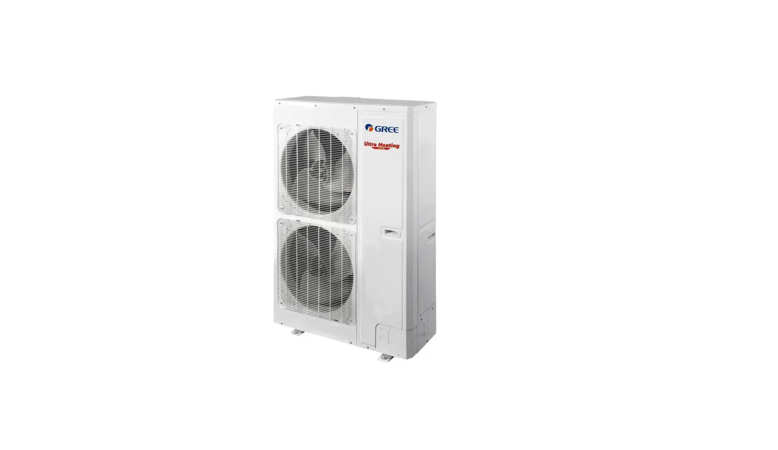
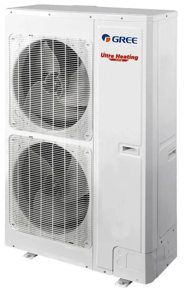
The product is an outdoor unit with different nominal capacities and SEER (Seasonal Energy Efficiency Ratio) ratings. It comes in Multi-Pro Single Fan Models and Multi-Pro Dual Fan Models. The Multi-Pro Ultra Heat Systems have a lower SEER rating but provide ultra heat capabilities. The product has different outdoor model numbers, pipe connections, and MCA (Minimum Circuit Amps) values based on the capacity and model type. It also has common indoor units, including high walls, ceiling cassettes, compact consoles/floor ceiling models, and different combinations of outdoor models.
Product Usage Instructions
- Choose the appropriate outdoor unit model based on your cooling and heating needs.
- Check the nominal capacities and SEER ratings to ensure they meet your requirements.
- Check the MCA and MOCP (Maximum Overcurrent Protection) values to ensure the electrical circuit can handle the unit’s power requirements.
- Check the recommended breaker size to ensure it is compatible with the electrical circuit.
- Check the factory charge of the outdoor unit to ensure it h as a sufficient refrigerant.
- Choose the appropriate indoor unit based on your preferences and space requirements.
- Follow the piping rules for single-zone piping or multi-zone piping based on your installation requirements.
- Connect the indoor and outdoor units using the appropriate pipe connections.
- Follow the installation guidelines provided in the user manual for proper installation and operation of the product.
Outdoor Units
| NOMINAL CAPACITIES | SEER | EER | HSPF | OUTDOOR MODEL NUMBERS | MIN/Max Connections | ODU Pipe Connections | Max Lift (ft.) | Min Line Length (ft.) | Max Line Length (ft.) | ODU Factory Charge | MCA | MOCP | Recommended Breaker Size | Rated Cooling Capacities | Rated Heating Capacities | Energy Star | AHRI NUMBERS | OUTDOOR DEMENSIONS | |
| Multi-Pro Single Fan Models | Single Zone Piping Rules | ||||||||||||||||||
| 24,000 | 18.00 | 11.00 | 10.00 | GMV-24WL/C-T(U) | One/Four | 5/8×3/8 | 98 | 10’ | 328 | 5.3 lbs. | 21 | 25 | 25 | 24,000 | 28,000 | Yes | 204344210 | 2 / 2.5 Ton | 3 / 4 / 5 Ton |
| 28,000 | 18.00 | 11.00 | 9.00 | GMV-28WL/C-T(U) | One/Four | 5/8×3/8 | 98 | 10’ | 328 | 5.3 lbs. | 21 | 30 | 30 | 28,000 | 30,000 | Yes | 204244211 | (HXWXD) | (HXWXD) |
| Multi-Pro Dual Fan Models | 31-1/8 x 38-9/16 x 14 3/16 | 53×35 3/8×13 3/8 | |||||||||||||||||
| 36,000 | 19.50 | 11.50 | 10.50 | GMV-36WL/C-T(U) | One/Seven | 5/8×3/8 | 164’ | 10’ | 394 | 7.3 lbs. | 28.5 | 35 | 30 | 37,500 | 42,000 | No | 206335353 |  |  |
| 48,000 | 19.50 | 11.00 | 10.60 | GMV-48WL/C-T(U) | One/Eight | 5/8×3/8 | 164’ | 10’ | 394 | 7.3 lbs. | 33 | 40 | 40 | 48,000 | 54,000 | Yes | 206335354 | ||
| 60,000 | 19.50 | 10.50 | 10.50 | GMV-60WL/C-T(U) | One/Ten | 3/4/3/8 | 164 | 10’ | 394 | 10.1l lbs. | 34.5 | 40 | 40 | 60,000 | 64,000 | No | 206335355 | ||
| Multi-Pro Ultra Heat Systems | |||||||||||||||||||
| 36,000 | 16.50 | 9.50 | 10.20 | GMV-36WL/B-T(U) | One/Five | 5/8×3/8 | 164’ | 10’ | 394 | 14.3 lbs. | 37 | 50 | 40 | 36,000 | 45,000 | Yes | 8654208 | ||
| 48,000 | 16.50 | 11.30 | 10.30 | GMV-48WL/B-T(U) | One/Seven | 5/8×3/8 | 164’ | 10’ | 394 | 14.3 lbs.’ | 37 | 50 | 40 | 48,000 | 54,000 | Yes | 8654211 | ||
Common Indoor Units
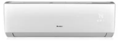
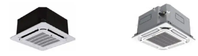
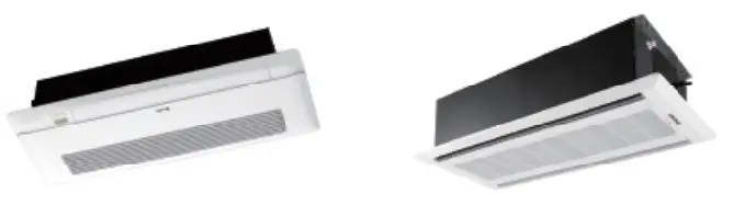
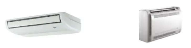
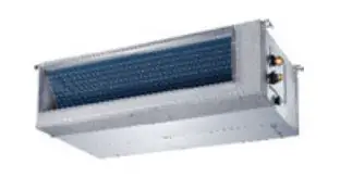
| HIGHWALLS | CEILING CASSETTES | COMPACT CONSOLE / FLOOR CEILING | SLIM DUCTED | VERTICAL AIR HANDLER | ||||||
 | 
|  |  |
|
AHU Models |
Auxiliary Heat Models | 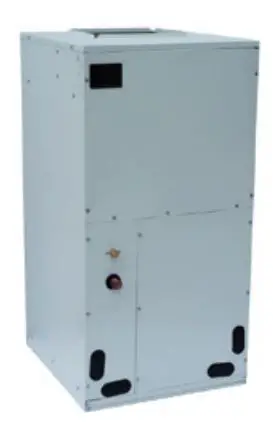
| |||
| High Wall Models | Cassette Models | GMV-ND09A/B-T(U) | Reference product data to select proper heater size by product model | |||||||
| GMV-ND06G/B4B-T(U) | Compact Cassette | Standard Cassette | One Way Cassette | Two Way Cassette | Compact Console | Floor Ceiling | GMV-ND07PHS/B-T(U) | GMV-ND12A/B-T(U) | ||
| GMV-ND07G/B4B-T(U) | GMV-ND07T/E-T(U) | GMV-ND09T/C-T(U) | GMV-ND07TD/A-T(U) | GMV-ND09TS/A-T(U) | GMV-ND07C/A-T(U) | GMV-ND09ZD/A-T(U) | GMV-ND09PHS/B-T(U) | GMV-ND18A/B-T(U) | ||
| GMV-ND09G/B4B-T(U) | GMV-ND09T/E-T(U) | GMV-ND12T/C-T(U) | GMV-ND09TD/A-T(U) | GMV-ND12TS/A-T(U) | GMV-ND09C/A-T(U) | GMV-ND12ZD/A-T(U) | GMV-ND12PHS/B-T(U) | GMV-ND24A/B-T(U) | ||
| GMV-ND12G/B4B-T(U) | GMV-ND12T/E-T(U) | GMV-ND18T/C-T(U) | GMV-ND12TD/A-T(U) | GMV-ND15TS/A-T(U) | GMV-ND12C/A-T(U) | GMV-ND18ZD/A-T(U) | GMV-ND18PHS/B-T(U) | GMV-ND30A/B-T(U) | FLEXXHTR5KW | |
| GMV-ND18G/B4B-T(U) | GMV-ND15T/E-T(U) | GMV-ND24T/C-T(U) | GMV-ND18TS/A-T(U) | GMV-ND18C/A-T(U) | GMV-ND24ZD/A-T(U) | GMV-ND24PHS/B-T(U) | GMV-ND36A/B-T(U) | FLEXXHTR8KW | ||
| GMV-ND24G/B4B-T(U) | GMV-ND18T/E-T(U) | GMV-ND36T/C-T(U) | GMV-ND24TS/A-T(U) | GMV-ND36ZD/A-T(U) | GMV-ND36PHS/B-T(U) | GMV-ND42A/B-T(U) | FLEXXHTR10KW | |||
| GMV-ND30G/B4B-T(U) | GMV-ND48T/C-T(U) | GMV-ND48ZD/A-T(U) | GMV-ND48PHS/B-T(U) | GMV-ND48A/B-T(U) | FLEXXHTR15KW | |||||
| GMV-ND36G/B4B-T(U) | Compact Grill | Standard Grill | One Way Grill | Two Way Grill | GMV-ND54PHS/B-T(U) | GMV-ND60A/B-T(U) | FLEXXHTR20KW | |||
| TF05 | TE01 | TD01 | TE03 | |||||||
Common Combinations
| Outdoor Models | Single Zone | Two Zones | Three Zones | Four Zones | Five Zones | Six to Ten Zones | |||||||
| GMV-24WL/C-T(U) | 12 | 24 | 9+9 | 9+18 | 6+6+6 | 7+7+7 | 6+6+6+6 | 6+7+7+9 |
Not applicable to these models |
When designing systems with six zones or more the Design Software must be used. | |||
| 15 | 30 | 9+12 | 9+24 | 6+6+7 | 6+6+7+7 | ||||||||
| 18 | 12+12 | 9+30 | 6+7+9 | 7+7+&+7 | |||||||||
| GMV-28WL/C-T(U) | 15 | 30 | 12+12 | 9+9+9 | 9+12+12 | 7+7+7+7 | |||||||
| 18 | 36 | 12+18 | 9+9+12 | 12+12+12 | |||||||||
| 24 | 18+18 | 9+9+18 | |||||||||||
| GMV-36WL/C-T(U) & GMV-36WL/B-T(U) Ultra Heat Model | 18 | 42 | 12+12 | 9+9+9 | 9+12+12 | 12+12+12 | 9+9+9+9 | 9+9+12+18 | 9+9+9+9+9 | ||||
| 24 | 12+18 | 9+9+12 | 9+12+18 | 12+12+18 | 9+9+9+12 | 9+12+12+12 | 9+9+9+9+12 | 9+9+9+18+18 | |||||
| 30 | 12+24 | 9+9+18 | 9+12+24 | 12+18+18 | 9+9+9+18 | 12+12+12+12 | 9+9+9+9+18 | 9+9+12+12+12 | |||||
| 36 | 18+18 | 9+9+24 | 9+18+18 | 12+12+24 | 9+9+12+12 | 9+9+9+9+24 | 9+9+12+12+18 | ||||||
| 9+9+9+12+12 | 9+12+12+12+12 | ||||||||||||
| 9+9+9+12+18 | 9+12+12+12+18 | ||||||||||||
| 9+9+9+12+24 | 12+12+12+12+12 | ||||||||||||
|
GMV-48WL/C-T(U) & GMV-48WL/B-T(U) Ultra Heat Model | 24 | 12+12 | 9+9+9 | 9+12+24 | 12+12+24 | 9+9+9+9 | 9+12+12+12 | 9+9+9+9+9 | 9+9+9+18+18 | ||||
| 30 | 12+18 | 9+9+12 | 9+18+18 | 12+18+18 | 9+9+9+12 | 9+12+12+18 | 9+9+9+9+12 | 9+9+12+12+12 | |||||
| 42 | 12+24 | 9+9+18 | 9+18+24 | 12+18+24 | 9+9+9+18 | 9+12+12+24 | 9+9+9+9+18 | 9+9+12+12+18 | |||||
| 48 | 18+18 | 9+9+24 | 9+24+24 | 12+24+24 | 9+9+9+24 | 9+12+18+18 | 9+9+9+9+24 | 9+12+12+12+12 | |||||
| 54 | 18+24 | 9+12+12 | 12+12+12 | 18+18+18 | 9+9+12+12 | 9+18+18+18 | 9+9+9+12+12 | 9+12+12+12+18 | Connected capacity of 50% minimum and up to 125% of the maximum rated capacity must be connected for the system to operate within factory speciifications. | ||||
| 60 | 24+24 | 9+12+18 | 12+12+18 | 18+18+24 | 9+9+12+18 | 12+12+12+12 | 9+9+9+12+18 | 12+12+12+12+12 | |||||
| 9+9+12+24 | 12+12+12+18 | ||||||||||||
| 9+9+18+18 | 12+12+12+24 | ||||||||||||
| 9+9+18+24 | 12+12+18+18 | ||||||||||||
|
GMV-60WL/C-T(U) | 30 | 12+18 | 7+12+12 | 9+24+24 | 9+9+9+9 | 9+12+12+12 | |||||||
| 36 | 9+24 | 9+9+12 | 12+12+12 | 9+9+9+12 | 9+12+12+18 | 9+9+9+9+9 | 9+9+9+18+18 | ||||||
| 48 | 12+12 | 9+9+18 | 12+12+18 | 9+9+9+18 | 9+12+12+24 | 9+9+9+9+12 | 9+9+12+12+12 | ||||||
| 54 | 12+18 | 9+9+24 | 12+12+24 | 9+9+9+24 | 9+12+18+18 | 9+9+9+9+18 | 9+9+12+12+18 | ||||||
| 60 | 12+24 | 9+12+12 | 12+18+18 | 9+9+12+12 | 9+18+18+18 | 9+9+9+9+24 | 9+12+12+12+12 | ||||||
| 18+18 | 9+12+18 | 12+18+24 | 9+9+12+18 | 12+12+12+12 | 9+9+9+12+12 | 9+12+12+12+18 | |||||||
| 18+24 | 9+12+24 | 12+24+24 | 9+9+12+24 | 12+12+12+18 | 9+9+9+12+18 | 12+12+12+12+12 | |||||||
| 24+24 | 24+36 | 9+18+18 | 18+18+18 | 9+9+18+18 | 12+12+12+24 | ||||||||
| 30+30 | 9+18+24 | 18+18+24 | 9+9+18+24 | 12+12+18+18 | |||||||||
Piping Rules
- Piping limitations are important and absolute. EXNO CEPTIONS.
- 98 4 fequivalent ofeet piping
- All piping lengths within the Piping Rules are in one direction, measuring the liquid line.
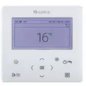
Control options
 XK46
XK46
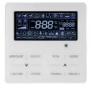
Wired Controller (Included with all Horizontal Ducted Units and AHU Kits) Optional for All Others XK46
XK46
Wireless remote control (Included with Ductless Units)
 XK46
XK46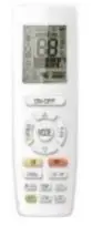 XK46
XK46 XE70-33/H
Included with Multiposition Air Handler. Optional for Others. Controller with 7-day programmable function, Max. Indoor unit connectable is 16
 XE70-33/H
 CE52-24/F Central Controller
Enables centralized local control. Can control and monitor up to 16 MultiPRO Systems with up to 32 indoor units. Expanded option also available. Enables 7-Day programming, grouping, and function lockout. ME30/24D1(BM) BACnet and Modbus Gateway
Converts GREE CAN bus to BACnet or Modbus building management protocols for monitoring and control of up to 16 MultiPRO systems and 160 indoor units.
 CE52-24/F Central Controller
 ME30/24D1(BM) BACnet and Modbus Gateway
Refrigerant Piping Installation Guidelines & Descriptions
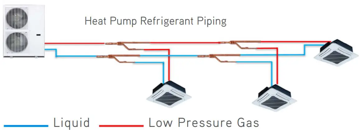
Refrigerant Piping
- Heat Pump has two pipes, liquid and gas
- Mode changes occur in outdoor unit

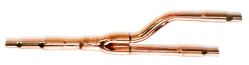
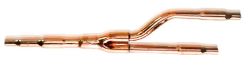
Y-Branches
- For even distribution of refrigerant to and from indoor units
- Specially engineered for even flow
- Different sizes dependent on capacity downstream

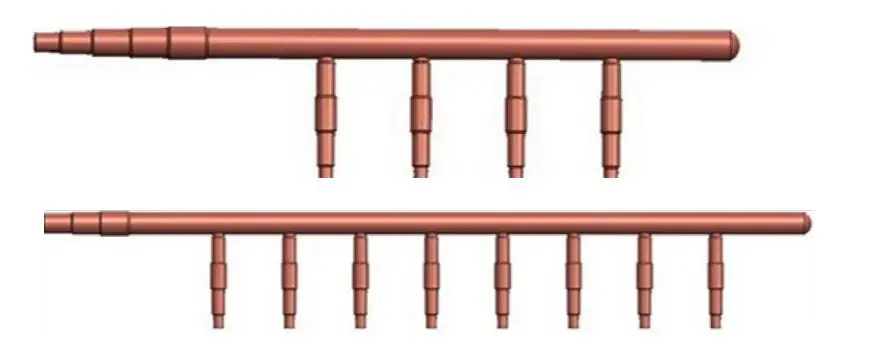
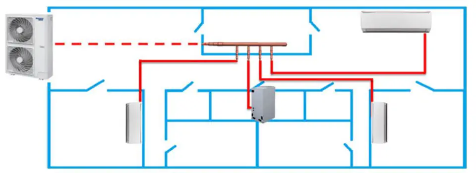
Headers
- Must be installed level
- Cannot have Y-Branch downstream
- Includes caps for unused ports

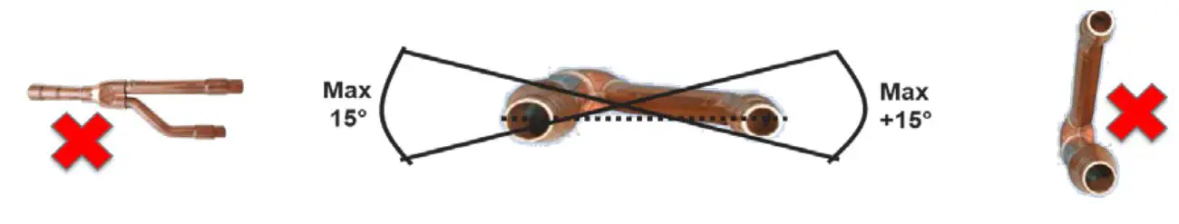
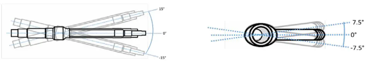
Y-Branches Installation
- Cannot be sideways, will cause poor performance
- Must be level or plumb within 15 degrees


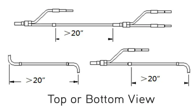
Y-Branch Installation
- Must have 20” between Y-Branches, elbows, and between Y-Branches and elbows
- Failure to meet these minimums can cause turbulence and refrigerant noise

Y-Branch Equivalent Length
- Equals 20” (0.5m)
- Used when calculating total piping and additional refrigerant charge

Basic Piping Rules Defined
Note: The following is a basic set of rules for piping lengths. The MultiPRO systems are capable of far greater lengths and more complex configurations. Use our MultiPRO System Builder, MultiPRO Selector, or see installation manual for more details
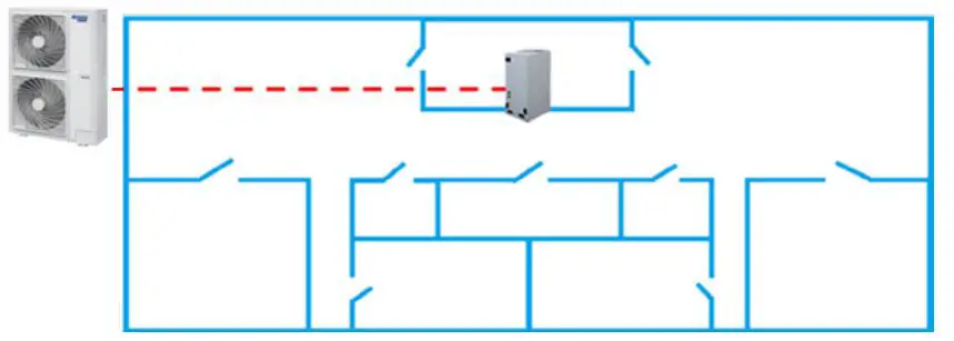
SINGLE ZONE
| Single Zone Piping Limits | 2 and 2.5T | 3, 4, and 5T |
| Maximum Length ODU to IDU: | 328′ | 393′ |
| Max Height ODU Above IDU: | 98′ | 164′ |
| Max Height ODU Below IDU: | 98′ | 131′ |
| Single Zone MultiPRO | ||
| The piping sizes are determined by ODU | ||
| Model | Liquid | Gas |
| 2 Ton Outdoor Unit | 3/8″ | 5/8″ |
| 2.5 Ton Outdoor Unit | 3/8″ | 5/8″ |
| 3 Ton Outdoor Unit | 3/8″ | 5/8″ |
| 4 Ton Outdoor Unit | 3/8″ | 5/8″ |
| 5 Ton Outdoor Unit | 3/8″ | 3/4″ |
| If necessary, reduce the piping size at the indoor unit | ||
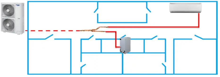
DUAL AND MULTIZONE
| Dual/Multi Zone Piping Limits | 2 and 2.5T | 3, 4, and 5T |
| Max Length IDU to Y-Branch or Header: | 98′ | 98′ |
| Max Height IDU to Y-Branch or Header: | 30′ | 30′ |
| Max Height ODU Above IDU: | 98′ | 98′ |
| Max Height ODU Below IDU: | 98′ | 98′ |
| Note: these are basic limitations. Actual limitations are far greater. Use MultiPRO System Builder, MultiPRO Selector, or see installation manuals for more details. | ||
| Dual and Multi Zone MultiPRO | ||||||
| Model Liquid Gas | Model Liquid Gas | |||||
| 2 Ton Outdoor Unit | 3/8″ | 5/8″ | 5 to 9kBtu | 1/4″ | 3/8″ | |
| 2.5 Ton Outdoor Unit | 3/8″ | 5/8″ | 12 to 15kBtu | 1/4″ | 1/2″ | |
| 3 Ton Outdoor Unit | 3/8″ | 5/8″ | 18 to 48kBtu | 3/8″ | 5/8″ | |
| 4 Ton Outdoor Unit | 3/8″ | 5/8″ | 54 and 60kBtu | 3/8″ | 3/4″ | |
| 5 Ton Outdoor Unit | 3/8″ | 3/4″ | Above 60kBtu | N/A | N/A | |
This guide is to be used for reference only and is not intended to replace the Installation Instructions or the design software. Always read and follow the software outputs and the Installation Instructions. Copyright Tradewinds Climate Systems. All rights reserved V 5.1.22


