SUNRISE MEDICAL VR2 Joystick Controller for Quickie Hula Powerchair Instruction Manual
Wheelchair Components
We at SUNRISE MEDICAL have been awarded the ISO-13485 certificate, which affirms the quality of our products at every stage, from R & D to production. Options or accessories shown are available at extra cost.
Introduction
This user manual
This user manual will help you to use and maintain the controller of your power wheelchair safely. This user manual is a supplement to Sunrise Medical’s general wheelchair user manual. When necessary this user manual refers to other manuals as shown below:![]() Wheelchair: Refers to the general wheelchair user manual.
Wheelchair: Refers to the general wheelchair user manual.![]() Battery charger: Refers to the user manual for the battery charger.
Battery charger: Refers to the user manual for the battery charger.
Read this user manual and the other user manuals referred to carefully before using the product. If one of the user manuals was not included with your wheelchair, please contact your dealer immediately.
In addition to this user manual, there is also a service manual for qualified specialists.
If you are visually impaired, this document can be viewed in PDF format at www.SunriseMedical.eu or alternatively is available on request in large text.
For further information
Please contact your local, authorised Sunrise Medical dealer if you have any questions regarding the use, maintenance or safety of your wheelchair. In case there is no authorised dealer in your area or you have any questions, contact Sunrise Medical either in writing or by telephone.
For information about product safety notices and product recalls, go to www.SunriseMedical.eu
Symbols used in this manual
Note!
Pointing out possible problems to the user.
![]() Caution!
Caution!
Advice for the user to prevent damage to the product.
![]() Warning!
Warning!
Warnings for the user to prevent personal in jury.
Not following these instructions may result in physical injury, damage to the product or damage to the environment!
The controller
VR2 controller
A controller will usually have three basic functions:
- Driving and steering a wheelchair
- Operating electrical seat adjustments
- Charging the wheelchairs batteries
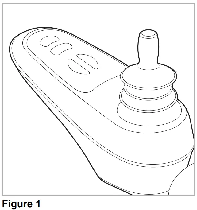
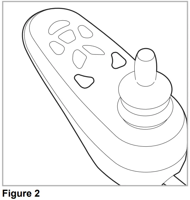
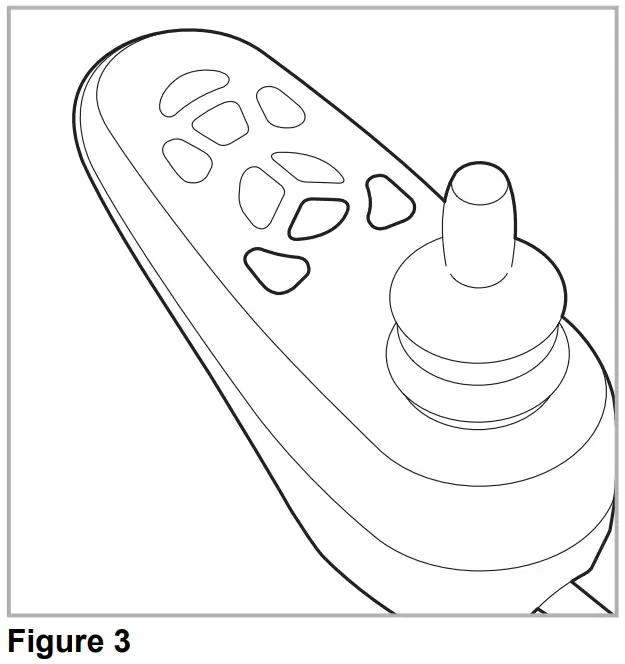
There are many different control systems for wheelchairs on the market. If the controller on your wheelchair does not resemble the one in figure 1, 2 or 3 contact your dealer.
- VR2 drive only

- VR2 Lights

- VR2 Seats&Lights

VR2 by PG Driving Technologies is a collective name for the entire control system of the wheelchair. The wheelchair is operated by means of a controller, which includes the following components:
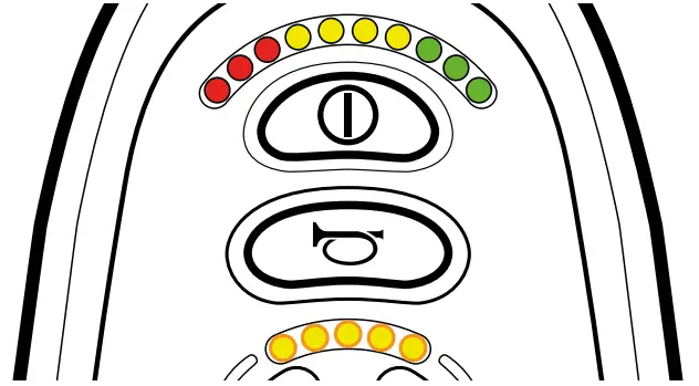
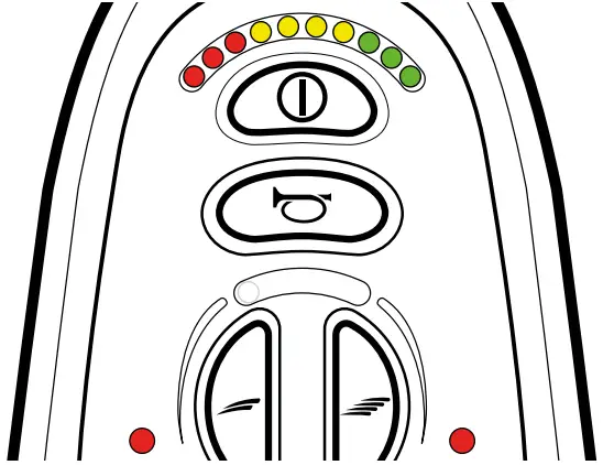
Figure 4 From the left to the right ; VR2 drive only, VR2 Lights, VR2 Seats & Lights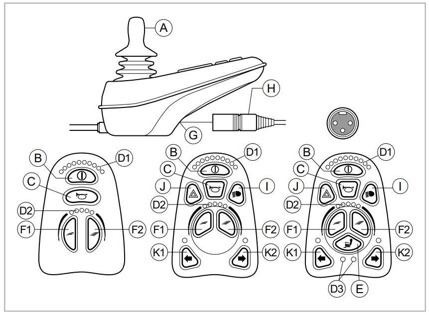
| Part | Function |
| A. Joystick | In the ´drive´ mode: driving and steering In the ‘adjustment options’ mode:
|
| B. On/off switch | Switching the controller on or off |
| C. Horn | Warning signal with sound |
| D.1 Battery indicator | Displays the power level of the battery |
| D.2 Maximum speed | Displays the maximum speed limit as set by the user |
| D.3 Adjustment option | Displays the selected adjustment options |
| E. “Mode” button | Changing between the ‘driving’ and the ‘adjustment options’ mode |
| F. 1 Speed regulator | Reduce driving speed (slower) |
| F. 2 Speed regulator | Increase driving speed (faster) |
| G. Charge connector | Input for the battery charger |
| H. Charge plug for the battery charger | Connector for the battery charger |
| I. Lights button | Switching the lights on or off |
| J. Hazard lights | Warning signal with lights |
| K. 1 Direction indicator left | Switches the left direction indicator on or off |
| K.2 Direction indicator right | Switches the right direction indicator on or off |
Driving the wheelchair with the controller
Switching the controller on or off
To be able to drive or operate the electronic adjustment options of the wheelchair, the controller must be switched on. Press the on/off button (B in figure 4).
Driving the wheelchair
Driving an electric wheelchair is done by operating a joystick. Move the joystick forwards and the wheelchair will also move forwards. Steer left and right and the wheelchair will turn.
Speed
The maximum speed can be controlled by the speed regulator on the controller (F1 en F2 in figure 4). The maximum speed is displayed by the LED lights above the speed regulators (D2 figure 4). Speed can be controlled with the joystick while driving. If the joystick is moved a little, the wheelchair will move more slowly
Operating the electrical adjustment options
Not every wheelchair has been equipped with electronic adjustment options. We make a distinction between four different adjustment options to the seating system:
Figure 5 Electrical adjustment options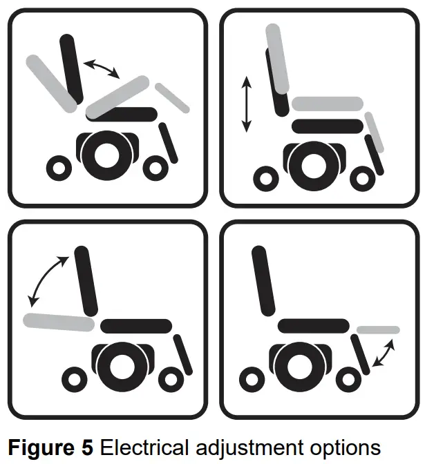
- Tilt adjustments
- High/low adjustments
- Backrest adjustments
- Legrest adjustments
To use electrical adjustment options, the VR2 Seats&Lights controller is required (maximum of two options).
Selecting the desired adjustment option
- Switch on the controller
- Press on the ‘mode’ button (E in figure 4) to select the ‘adjustment options’ mode. The controller will now be in the ‘adjustment options’ mode. It is also possible to follow the status.
The joystick is used to select and operate the electronic adjustment options. - Move the joystick to the left or the right to select the desired adjustment option. The selected adjustment option will be visible on the display screen.
- Moving the joystick forwards and/or backwards will activate the selected electronic adjustment option (see table 6). Move the joystick forwards or backwards until the desired adjustment option has been attained.
Table 1 Electrical adjustmentsMove joystick backwards Move joystick forwards Tilt adjustment The entire chair will tilt backwards The entire chair will tilt forwards High/low adjustments The entire chair will be raised The entire chair will be lowered Backrest adjustments The backrest will tilt backwards The backrest will tilt forwards Legrest adjustments The legrest angle will increase, the footplate will be raised The legrest angle will decrease, the footplate will be lowered - To return to the ‘drive’ mode: Press on the ‘mode’ button to select the ‘drive’ mode
Note: If you adjust the seat height by using the high/low option or use the electrical tilt adjustment 0 – 45°, the speed will be reduced due to safety reasons.
Lights
Not every wheelchair has been equipped with lights. You can activate the following functions only by using VR2 Lights and/or VR2 Seat&Lights:
- Lights (I in figure 4)
- Hazard Lights (J in figure 4)
- Direction indicators (K1 & K2 in figure 4)
Troubleshooting (Fig. 6)
If the wheelchair will not function while the batteries are fully charged, check the following points before consulting your dealer:
- Switch the controller off and then switch it on again. Check to see if the malfunction has been solved.
- Check if the free wheel switch was switched to Drive.
- Check if the joystick was in the 0 position when the controller was switched on. In other words, the joystick must not be moved when the controller is being switched on or off.
Malfunctions list
An extended malfunction list can be found in the appendix of the service manual (for qualified specialists only). The service manual can be found on www.SunriseMedical.eu
Fig. 6 On-board Diagnostics:
 | An excessive voltage has been applied to the control system. This is usually caused by a poor battery connection. Check the battery connections |
 | The parking brakes have a bad connection. Check the parking brake and the motor connections. Make sure that the control system connections are secure |
 | A control system fault is indicated. Make sure the control system connections are secure. |
 | A joystick fault is indicated. Make sure that the joystick is in the centre position before switching on the control system |
 | The wheelchair is being prevented from driving by an external signal. One possibility is that the battery charger is plugged in. |
 | The right hand motor has a short circuit to a battery connection. Contact your Sunrise Medical Authorised Dealer |
 | The right hand motor has a bad connection. Check the connections to the right hand motor. |
 | The left hand motor has a short circuit to a battery connection. Contact your Sunrise Medical Authorised Dealer. |
 | The left hand motor has a bad connection. Check the connections to the left hand motor. |
 | The batteries need charging, or there is a bad connection to the battery. Check the connections to the battery. If the connections are good, try charging the batteries |
 | S=Speed indicator LED’s A communication fault is indicated. Make sure that the joystick cable is securely connected and not damaged |
 | A=Actuator LED’s An actuator trip is indicated. If more than one actuator is fitted, check which actuator is not working. Check the actuator wiring. |
Locking the controller
To lock the controller;
- While the control system is switched on, depress and hold the on/off button.
- After 1 second the control system will beep.
Now release the on/off button - Deflect the joystick forwards until the control system beeps.
- Deflect the joystick in reverse until the control system beeps.
- Release the joystick, there will be a long beep.
- The wheelchair is now locked.
To unlock the controller;
- If the control system has switched off, press the on/off button.
- Deflect the joystick forwards until the control system beeps.
- Deflect the joystick in reverse until the control system beeps.
- Release the joystick, there will be a long beep.
- The wheelchair is now unlocked.
Technical specifications
| Supply Voltage: | 24 Vdc |
| Operating Voltage: | 16Vdc to 35Vdc |
| Peak Voltage: | 35Vdc |
| Reverse Battery Voltage: | 40Vdc |
| PWM Frequency: | 20kHz ± 0.5% |
| Brake Voltage: | 12Vdc or 24Vdc |
| Brake Current: | 100mA min. 1A max. |
| Charger Connector: | Use only Neutrik NC3MX |
| Batt. Charging Current: | 12Arms max. |
| Actuator Current: | 12A max. |
| Maximum Drive Current: | VR2 50 50A VR2 60 60A VR2 70 70A VR2 90 90A |
| Moisture Resistance: | IPx4 |
| Operating Temperature: | -25°C to +50°C |
| Storage Temperature: | -40°C to +65°C |
EMC tested on sample wheelchair:
| Susceptibility: | Tested at 30V/m to EN12184 (1999) and ANSI/ RESNA requirements |
| Emissions: | To EN55022 Class B |
| ESD: | IEC801 part 2 |
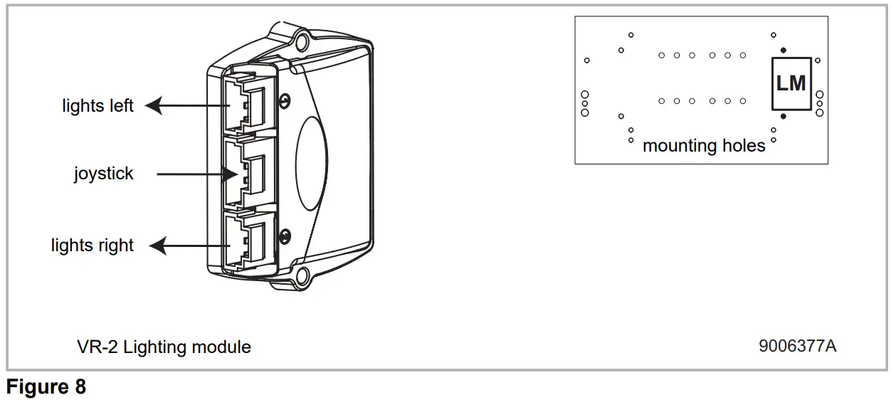
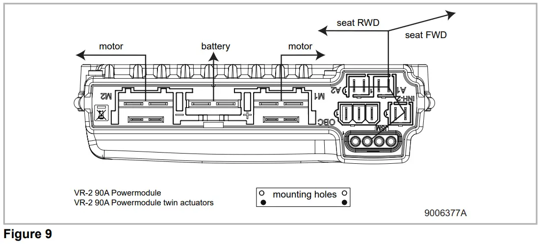
Technical diagrams
Technical diagram
The technical diagrams can also be found on the cover of the specific electronic component.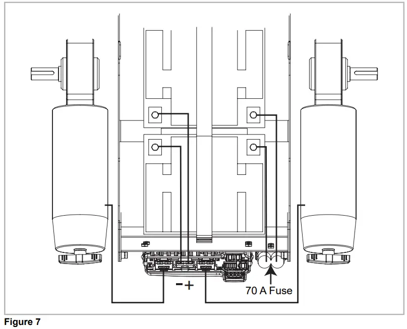
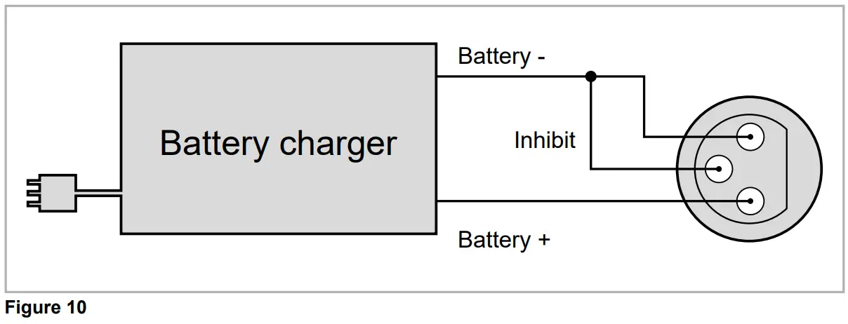
Technical diagram battery charger
The controller’s standard configuration includes a ‘3-pin connection’. Ensure that the battery charger is properly connected so that the ‘negative pole’ and the ‘inhibit’ are connected, enabling the system to prevent the wheelchair from moving when the battery is being charged.