![]()
Colours of light
USER´S MANUAL
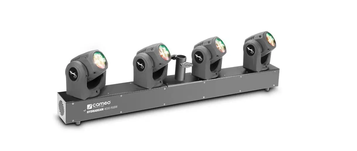
4 HEAD MOVING BAR HYDRABEAM 4000 CLHB4000RGBW
![]()
YOU‘VE MADE THE RIGHT CHOICE!
We have designed this product to operate reliably over many years. Please read this User‘s Manual carefully, so that you can begin making optimum use of your Cameo Light product quickly. Learn more about Cameo Light on our website WWW.CAMEOLIGHT.COM.
PREVENTIVE MEASURES
- Please read these instructions carefully.
- Keep all information and instructions in a safe place.
- Follow the instructions.
- Observe all safety warnings. Never remove safety warnings or other information from the equipment.
- Use the equipment only in the intended manner and for the intended purpose.
- Use only sufficiently stable and compatible stands and/or mounts (for fixed installations). Make certain that wall mounts are properly installed and secured. Make certain that the equipment is installed securely and cannot fall down.
- During installation, observ e the applicable safety regulations for your country.
- Never install and operate the equipment near radiators, heat registers, ovens, or other sources of heat. Make certain that the equipment is always installed so that is cooled sufficiently and cannot overheat.
- Never place sources of ignition, e.g., burning candles, on the equipment.
- Ventilation slits must not be blocked.
- Keep a minimum distance of 20 cm around and above the device.
- Do not use this equipment in the immediate vicinity of water (does not apply to special outdoor equipment – in this case, observe the special instructions noted below. Do not expose this equipment to flammable materials, fluids or gases. Avoid direct sunlight!
- Make certain that dripping or splashed water cannot enter the equipment. Do not place containers filled with liquids, such as vases or drinking vessels, on the equipment.
- Make certain that objects cannot fall into the device.
- Use this equipment only with the accessories recommended and intended by the manufacturer.
- Do not open or modify this equipment.
- After connecting the equipment, check all cables in order to prevent damage or accidents, e.g., due to tripping hazards.
- During transport, make certain that the equipment cannot fall down and possibly cause property damage and personal injuries.
- If your equipment is no longer functioning properly, if fluids or objects have gotten inside the equipment or if it has been damaged in her way, switch it off immediately and unplug it from the mains outlet (if it is a powered device). This equipment may only be repaired by authorized, qualified personnel.
- Clean the equipment using a dry cloth.
- Comply with all applicable disposal laws in your country. During disposal of packaging, please separate plastic and paper/cardboard.
- Plastic bags must be kept out of reach of children.
- Please note that changes or modifications not expressly approved by the party responsible for compliance could void the user´s authority to operate the equipment.
FOR EQUIPMENT THAT CONNECTS TO THE POWER MAINS: - CAUTION: If the power cord of the device is equipped with earthing contact, then it must be connected to an outlet with a protective
ground. Never deactivate the protective ground of a power cord. - If the equipment has been exposed to strong fluctuations in temperature (for example, after transport), do not switch it on immediately. Moisture and condensation could damage the equipment. Do not switch on the equipment until it has reached room temperature.
- Before connecting the equipment to the power outlet, first, verify that the mains voltage and frequency match the values specified on the equipment. If the equipment has a voltage selection switch, connect the equipment to the power outlet only if the equipment values and the mains power values match. If the included power cord or the power adapter does not fit in your wall outlet, contact your electrician.
- Do not step on the power cord. Make certain that the power cable does not become kinked, especially at the main outlet and/or power adapter and the equipment connector.
- When connecting the equipment, make certain that the power cord or power adapter is always freely accessible. Always disconnect the equipment from the power supply if the equipment is not in use or if you want to clean the equipment. Always unplug the power cord and power adapter from the power outlet at the plug or adapter and not by pulling on the cord. Never touch the power cord and power adapter with wet hands.
- Whenever possible, avoid switching the equipment on and off in quick succession because otherwise, this can shorten the useful life of the equipment.
- IMPORTANT INFORMATION: Replace fuses only with fuses of the same type and rating. If a fuse blows repeatedly, please contact an authorized service center.
- To disconnect the equipment from the power mains completely, unplug the power cord or power adapter from the power outlet
- If your device is equipped with a Volex power connector, the mating Volex equipment connector must be unlocked before it can be removed. However, this also means that the equipment can slide and fall down if the power cable is pulled, which can lead to personal injuries and/or other damage. For this reason, always be careful when laying cables.
- Unplug the power cord and power adapter from the power outlet if there is a risk of a lightning strike or before extended periods of disuse.
- The device must only be installed in a voltage-free condition (disconnect the mains plug from the mains).
- Dust and other debris inside the unit may cause damage. The unit should be regularly serviced or cleaned (no guarantee) depending on ambient conditions (dust etc., nicotine, fog) by qualified personnel to prevent overheating and malfunction.
- Please keep a distance of at least 0.5 m to any combustible materials.
- Power cables to power multiple devices must have a cross-section of at least 1.5 mm². Within the EU, the cables must correspond to H05VV-F, or similar. Suitable cables are offered by Adam Hall. With these cables, you can connect multiple devices via the power OUT connection to the power IN connection of an additional device. Make sure that the total current consumption of all connected devices does not exceed the specified value on all connected devices (label on the device). Make sure to keep power cable connections as short as possible.
 CAUTION:
To reduce the risk of electric shock, do not remove the cover (or back). There are no user-serviceable parts inside. Maintenance and repairs should be exclusively carried out by qualified service personnel.
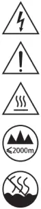 | The warning triangle with the lightning symbol indicates dangerous uninsulated voltage inside the unit, which may cause an electrical shock. |
| The warning triangle with an exclamation mark indicates important operating and maintenance instructions. | |
| Warning! This symbol indicates a hot surface. Certain parts of the housing can become hot during operation. After use, wait for a cool-down period of at least 10 minutes before handling or transporting the device. | |
| Warning! This device is designed for use below 2000 meters in altitude. | |
| Warning! This product is not intended for use in tropical climates. |
CAUTION! HIGH VOLUMES IN AUDIO PRODUCTS!
This device is meant for professional use. Therefore, commercial use of this equipment is subject to the respectively applicable national accident prevention rules and regulations. As a manufacturer, Adam Hall is obligated to notify you formally about the existence of potential health risks.
Hearing damage due to high volume and prolonged exposure: When in use, this product is capable of producing high sound-pressure levels (SPL) that can lead to irreversible hearing damage in performers, employees, and audience members. For this reason, avoid prolonged exposure to volumes in excess of 90 dB.
INTRODUCTION
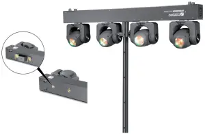
4 HEAD MOVING BAR HYDRABEAM 4000
CLHB4000RGBW
CONTROL FUNCTIONS
6-channel, 10-channel, 19-channel, 32-channel, 56-channel DMX control
Master/slave mode
Standalone operation
FEATURES
4 ultra-fast and individually-controlled moving heads. 4 high-performance 32 W RGBW Quad LEDs 5 DMX modes. DMX-512 control. Master/slave mode. Standalone programs. Sound control via built-in microphone. Universal mounting options. 2 Omega brackets and a tripod flange included. Operating voltage 100 – 240 V AC / 50 – 60 Hz. Power consumption 220 W
OPERATION
The Cameo Hydrabeam 4000 RGBW is a DMX-512-controllable 4-piece LED moving head that can be used as a standalone unit, in master /slave mode, or operated by sound control.
CONNECTIONS, OPERATING, AND DISPLAY ELEMENTS
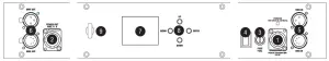
- POWER IN
Blue power input socket for power supply to the device. A suitable power cable is included. - POWER OUT
White power output socket for power supply to additional CAMEO lights. Ensure that the total current consumption of all connected devices does not exceed the value specified on the device in amperes (A). - FUSE
Fuse holder with F3AL / 250 V fuse (5 x 20 mm). IMPORTANT: When replacing the fuse, only use a fuse of the same type and value. In the event of repeated fuse failure, please contact an authorized service center. - POWER
On / off switch. - DMX IN
Male 3-pin and 5-pin XLR sockets for connection to a DMX control device (e.g. DMX console). - DMX OUT
Female 3-pin and 5-pin XLR socket for sending the DMX control signal. - LC DISPLAY
The LED display shows the operating mode and other system information. - OPERATING KEYS
MENU
Press MENU to access the selection menu for system settings. Press repeatedly to go back to the main display.
UP and DOWN
Select individual items in the selection menu and sub-menus for system settings (DMX address, operating mode, etc.). Change settings in the menu items.
ENTER
Press ENTER to access the menu levels and change values as required, e.g. the DMX address. Confirm value changes. - EYELET FOR SAFETY CABLE
Overhead installation may only be carried out by qualified personnel. A suitable safety cable must be fitted to the floodlight’s eyelet to ensure that it does not fall down.
OPERATION
NOTE
When the lamp is correctly connected to the mains supply and the standby switch is on, the CAMEO logo is shown on the display during start-up and motor reset. Once this process is complete, the spotlight is ready for operation and the previously selected operating mode is activated.
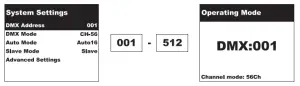
CONFIGURE DMX START ADDRESS
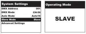
Press MENU to access the selection menu for system settings. Select the menu item “DMX Address” (shaded in color) using UP and DOWN and confirm with entering. A number field is now displayed and you can set the DMX start address as required, from 001 to 512, using the UP and DOWN buttons (hold down the button to change values quickly). Confirm with entering and press MENU to return to the main display. After approx. one minute of no input, the main display is automatically activated, the DMX start address is shown clearly at the center of the display and the DMX mode appears in the bottom line (6Ch, 10Ch, 19Ch, 32Ch, 56Ch).
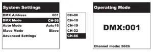
CONFIGURE DMX MODE
Press MENU to access the selection menu for system settings. Select the menu item “DMX Mode” (shaded in color) using UP and DOWN and confirm with entering. A selection field is then displayed and you can set the desired DMX mode using the UP and DOWN buttons. Confirm with entering and press MENU to return to the main display. After approx. one minute of no input, the main display is automatically activated, the DMX start address is shown clearly at the center of the display and the DMX mode appears in the bottom line (6Ch, 10Ch, 19Ch, 32Ch, 56Ch).
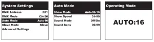
CONFIGURE AUTO MODE
The 17 available auto programs each consist of a series of non-editable color-change and motion sequences. Press MENU to access the selection menu for system settings. Select the menu item “Auto Mode” (shaded in color) using UP and DOWN, and confirm with entering. Select the menu item “Show Mode” using the UP and DOWN buttons, confirm with entering, then select the required program, Auto0 to Auto16, using UP and DOWN again, then confirm with entering. You can set the program speed by selecting the menu item “Show Speed” using the UP and DOWN buttons, confirming with entering, and then using UP and DOWN once again to select a value between 01 and 99 (hold button down to change values quickly, 01 = minimum and 99 = maximum speed). Confirm with ENTER and press MENU twice to return to the main display. After approx. one minute of no input, the main display is automatically activated and the selected auto program is shown clearly at the center of the display.
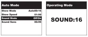
ACTIVATE SOUND CONTROL
Select one of the auto programs as described above under CONFIGURE AUTO MODE. Now select the menu item “Sound Mode” (shaded in color) using UP and DOWN, confirm with entering, then use UP and DOWN again to select “On” and confirm with entering. You can set the microphone sensitivity by selecting the menu item “Sound Sens” using the UP and DOWN buttons, confirming with entering and then using UP and DOWN once again to select a value between 00 and 99 (hold button down to change values quickly, 00 = minimum and 99 = maximum sensitivity). Confirm with entering and press MENU twice to return to the main display. After approx. one minute of no input, the main display is automatically activated and the selected sound program is shown clearly at the center of the display. Now the spotlight is controlled via the built-in microphone and follows the beat of the music (bass impulses).
SLAVE MODE
Press MENU to access the selection menu for system settings. Select the menu item “Slave Mode” (shaded in color) using UP and DOWN, and confirm with entering. Press MENU to return to the main display. After approx. one minute of no input, the main display is automatically activated and SLAVE is shown clearly at the center of the display. Connect the slave and the master units (same model) with a DMX cable, and enable one of the standalone modes on the master unit (Auto, Sound). The slave unit will now follow the master unit.
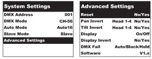
ADVANCED SETTINGS
Press MENU to access the selection menu for system settings. Select the menu item “Advanced Settings” (shaded in color) using UP and DOWN, and confirm with entering. This will take you to the sub-menu for configuring the following sub-menu items (selecting using UP and DOWN, confirm with entering):
| Advanced Settings | ||||
| Reset | = | Reset motors | Yes. | Reset pan and tilt motors |
| No | = Discontinue pan and tilt motor reset | |||
| Pan Invert | = | Head pan direction | No | = No reversal of pan direction |
| Head2 pan direction | ||||
| Head3 pan direction | Yes. | = Reversal of pan direction | ||
| Head4 pan direction | ||||
| Tilt Invert | = | Head1 tilt direction | No | = No reversal of tilt direction |
| Head2 tilt direction | ||||
| Head3 tilt direction | Yes. | = Reversal of tilt direction | ||
| Head4 tiff direction | ||||
| Display | = | Display lighting | On | = Permanently on |
| Off | = Deactivation after one minute of inactivity | |||
| Display invert | = | Rotate display | On | = Rotate display by 180° (e.g. for overhead installation) |
| Off | = No display rotation | |||
| DMX Fall | = | Operating status with DMX signal fault | Auto | = Activates auto mode |
| Black | = Activates blackout | |||
| Hold | = Last command is retained | |||
| Software | = | Display device software | ENTER | Vl.x |
INSTALLATION
Thanks to its integrated rubber feet, the spotlight can be positioned in a suitable location on the stage floor, etc. Installation on a traverse is possible using the two Omega brackets supplied (only use original accessories) together with the appropriate traverse clamps (not included). Attach the device securely at the specified position using a suitable safety cable.
Important: Overhead installation may only be carried out by qualified personnel. Installation on a suitable tripod is possible using the integrated 35 mm tripod flange.
DMX TECHNOLOGY
DMX-512
DMX (Digital Multiplex) is the designation for a universal transmission protocol for communications between corresponding devices and controllers. A DMX controller sends DMX data to the connected DMX device(s). The DMX data is always transmitted as a serial data stream that is forwarded from one connected device to the next via the “DMX IN” and “DMX OUT” connectors (XLR plug-type connectors) that are found on every DMX-capable
device provided the maximum number of devices does not exceed 32 units. The last device in the chain needs to be equipped with a terminator (terminating resistor).
DMX CONNECTION
DMX is the common “language” via which a very wide range of types and models of equipment from various manufacturers can be connected with one another and controlled via a central controller, provided that all of the devices and the controller are DMX compatible. For optimum data transmission, it is necessary to keep the connecting cables between the individual devices as short as possible. The order in which the devices are integrated into the DMX network has no influence on the addresses. Thus the device with the DMX address 1 can be located at any position in the (serial) DMX chain: at the beginning, at the end, or somewhere in the middle. If DMX address 1 is assigned to a device, the controller “knows” that it should send all data allocated to address 1 to this device regardless of its position in the DMX network.
SERIAL CONNECTION OF MULTIPLE LIGHTS
- Connect the male XLR connector (3-pin or 5-pin) of the DMX cable to the DMX output (female XLR socket) of the first DMX device (e.g. DMX-Controller).
- Connect the female 3-pin XLR connector of the DMX cable connected to the first projector to the DMX input (male 3-pin socket) of the next DMX device. In the same way, connect the DMX output of this device to the DMX input of the next device and repeat until all devices have been connected. Please note that as a rule, DMX devices are connected in series and connections cannot be shared without active splitters. The maximum number of DMX devices in a DMX chain should not exceed 32 units. The Adam Hall 3 STAR, 4 STAR, and 5 STAR product ranges include an extensive selection of suitable cables.
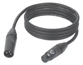
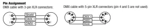
DMX CABLES
When fabricating your own cables, always observe the illustrations on this page. Never connect the shielding of the cable to the ground contact of the plug, and always make certain that the shielding does not come into contact with the housing of the XLR plug. If the shielding is connected to the ground, this can lead to short-circuiting and system malfunctions.
DMX TERMINATORS (TERMINATING RESISTORS)
To prevent system errors, the last device in a DMX chain needs to be equipped with a terminating resistor (120 ohms, 1/4 Watt).
3-pin XLR connector with a terminating resistor: K3DMXT3
5-pin XLR connector with a terminating resistor: K3DMXT5 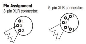
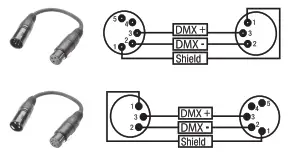
DMX ADAPTER
The combination of DMX devices with 3-pin connectors and DMX devices with 5-pin connectors in a DMX chain is possible with suitable adapters.
Pin Assignment
DMX Adapter 5-pin XLR male to 3-pin XLR female: K3DGF0020 Pins 4 and 5 are not used.
Pin Assignment
DMX Adapter 3-pin XLR male to 5-pin XLR female: K3DHM0020 Pins 4 and 5 are not used.
TECHNICAL DATA
| Model name: | CLHB4000RGBW |
| Product Type: | LED moving lights |
| Type: | Moving head bar |
| Color spectrum: | RGBW |
| No. of LEDs: | 4 |
| LED type: | 32 W quad |
| Dispersion angle: | 2.5° |
| DMX input: | 3-pin male XLR |
| DMX output: | 3-pin female XLR |
| DMX mode: | 6-channel, 10-channel, 19-channel, 32-channel, 56-channel |
| DMX functions: | Pan/tilt, pan/tilt fine, single head control, auto programs, sound control, color macros, stroboscope, dimmer |
| Standalone functions: | Auto programs, sound control, master/slave |
| Control: | USITT DMX512 |
| Operating controls: | MENU, ENTER, UP, DOWN |
| Indicators: | 4-digit LED display |
| PAN angle: | 540° |
| TILT angle: | 270° |
| Operating voltage: | 100 – 240 V AC / 50 – 60 Hz. |
| Power consumption: | 220 W |
| Light intensity (@ 1 m): | Single Head R: 17900, G: 42400, B: 9600, W: 67200 lx |
| Mains input socket: | Blue power twist connector |
| Mains output socket: | White power twist connector |
| Fuse: | F3AL/250 V (5 x 20 mm) |
| Ambient temperature (for operation): | 0 °C – 40 °C |
| Relative air humidity: | < 80%, non-condensing |
| Housing material: | Metal, ABS |
| Housing color: | Black |
| Housing cooling: | Low-noise fan |
| Dimensions (W x H x D, not including mounting bracket): | 1000 x 270 x 90 mm |
| Weight: | 12 kg |
| Additional features: | Power cable, 35 mm tripod flange, and Omega mounting bracket included |
MANUFACTURER´S DECLARATIONS
MANUFACTURER‘S WARRANTY & LIMITATIONS OF LIABILITY
You can find our current warranty conditions and limitations of liability at: http://www.adamhall.com/media/shop/downloads/documents/manufacturersdeclarations.pdf. To request warranty service for a product, please contact Adam Hall GmbH, Daimler Straße 9, 61267 Neu Anspach / Email: [email protected] / +49 (0)6081 / 9419-0.
CORRECT DISPOSAL OF THIS PRODUCT (valid in the European Union and other European countries with a differentiated waste collection system)
This symbol on the product, or on its documents indicates that the device may not be treated as household waste. This is to avoid environmental damage or personal injury due to uncontrolled waste disposal. Please dispose of this product separately from other waste and have it recycled to promote sustainable economic activity. Household users should contact either the retailer where they purchased this product, or their local government office, for details on where and how they can recycle this item in an environmentally friendly manner. Business users should contact their suppliers and check the terms and conditions of the purchase contract. This product should not be mixed with other commercial waste for disposal.
CE Compliance
Adam Hall GmbH states that this product meets the following guidelines (where applicable):
R&TTE (1999/5/EC) or RED (2014/53/EU) from June 2017
Low voltage directive (2014/35/EU)
EMV directive (2014/30/EU)
RoHS (2011/65/EU)
The complete declaration of conformity can be found at www.adamhall.com.
Furthermore, you may also direct your inquiry to [email protected].
DMX CONTROL
| 6-CH Mode | |||||
| CH1 | master dimmer | 000 | – | 255 | 0-100% |
| CH2 | strobe | 000 | – | 010 | no strobe |
| 011 | – | 255 | slow to fast | ||
|
CH3 |
show mode | 000 | – | 007 | no movement |
| 008 | – | 022 | show mode 1 | ||
| 023 | – | 037 | show mode 2 | ||
| 038 | – | 052 | show mode 3 | ||
| 053 | – | 067 | show mode 4 | ||
| 068 | – | 082 | show mode 5 | ||
| 083 | – | 097 | show mode 6 | ||
| 098 | – | 112 | show mode 7 | ||
| 113 | – | 127 | show mode 8 | ||
| 128 | – | 142 | show mode 9 | ||
| 143 | – | 157 | show mode 10 | ||
| 158 | – | 172 | show mode 11 | ||
| 173 | – | 187 | show mode 12 | ||
| 188 | – | 202 | show mode 13 | ||
| 203 | – | 217 | show mode 14 | ||
| 218 | – | 232 | show mode 15 | ||
| 233 | – | 247 | show mode 16 | ||
| 248 | – | 255 | sound control mode | ||
| CH4 | 000 | – | 255 | show mode speed (slow to fast) / sound sensitivity | |
| CH5 | light control | 000 | – | 030 | automatic color change |
| 031 | – | 255 | color macro (see color macro table) | ||
| CH6 | 000 | – | 255 | automatic color change speed | |
| 10-CH Mode | |||||
| CH1 | master control | 000 | – | 255 | pan |
| CH2 | 000 | – | 255 | tilt | |
| CH3 | 000 | – | 255 | master dimmer 0-100% | |
| CH4 | strobe | 000 | – | 010 | no strobe |
| 011 | – | 255 | slow to fast | ||
| colour macro: | |
| 031 – 045 | R |
| 046 – 060 | G |
| 061 – 075 | B |
| 076 – 090 | W |
| 091 – 105 | RG |
| 106 – 120 | RB |
| 121 – 135 | RW |
| 136 – 150 | GB |
| 151 – 165 | GW |
| 166 – 180 | BW |
| 181 – 195 | RGB |
| 196 – 210 | RGW |
| 211 – 225 | RBW |
| 226 – 240 | GBW |
| 241 – 255 | RGBW |
|
CH5 |
show mode | 000 | – | 007 | no movement |
| 008 | – | 022 | show mode 1 | ||
| 023 | – | 037 | show mode 2 | ||
| 038 | – | 052 | show mode 3 | ||
| 053 | – | 067 | show mode 4 | ||
| 068 | – | 082 | show mode 5 | ||
| 083 | – | 097 | show mode 6 | ||
| 098 | – | 112 | show mode 7 | ||
| 113 | – | 127 | show mode 8 | ||
| 128 | – | 142 | show mode 9 | ||
| 143 | – | 157 | show mode 10 | ||
| 158 | – | 172 | show mode 11 | ||
| 173 | – | 187 | show mode 12 | ||
| 188 | – | 202 | show mode 13 | ||
| 203 | – | 217 | show mode 14 | ||
| 218 | – | 232 | show mode 15 | ||
| 233 | – | 247 | show mode 16 | ||
| 248 | – | 255 | sound control mode | ||
| CH6 | 000 | – | 255 | show mode speed (slow to fast) / sound sensitivity | |
| CH7 | light control | 000 | – | 030 | automatic color change |
| 031 | – | 255 | color macro (see color macro table) | ||
| CH8 | 000 | – | 255 | automatic color change speed (slow to fast ) | |
| CH9 | fine control | 000 | – | 255 | pan fine |
| CH10 | 000 | – | 255 | tilt fine |
| 19-CH Mode | |||||
| CH1 | master dimmer | 000 | – | 255 | master dimmer 0-100% |
| CH2 | strobe | 000 | – | 010 | no strobe |
| 011 | – | 255 | slow to fast | ||
| CH3 |
colour control | 000 | – | 255 | red dimmer |
| CH4 | 000 | – | 255 | green dimmer | |
| CH5 | 000 | – | 255 | blue dimmer | |
| CH6 | 000 | – | 255 | white dimmer | |
| CH7 | first head | 000 | – | 255 | pan |
| CH8 | 000 | – | 255 | tilt | |
| CH9 | 000 | – | 255 | dimmer 0-100% | |
| CH10 | second head | 000 | – | 255 | pan |
| CH11 | 000 | – | 255 | tilt | |
| CH12 | 000 | – | 255 | dimmer 0-100% | |
| CH13 | third head | 000 | – | 255 | pan |
| CH14 | 000 | – | 255 | tilt | |
| CH15 | 000 | – | 255 | dimmer 0-100% | |
| CH16 | fourth head | 000 | – | 255 | pan |
| CH17 | 000 | – | 255 | tilt | |
| CH18 | 000 | – | 255 | dimmer 0-100% | |
| CH19 | head speed | 000 | – | 255 | fast to slow |
| 32-CH Mode | |||||
| CH1 | master dimmer | 000 | – | 255 | dimmer 0-100% |
| CH2 | strobe | 000 | – | 010 | no strobe |
| 011 | – | 255 | slow to fast | ||
| CH3 |
first head | 000 | – | 255 | first head, pan |
| CH4 | 000 | – | 255 | first head, pan fine | |
| CH5 | 000 | – | 255 | first head, tilt | |
| CH6 | 000 | – | 255 | first head, tilt fine | |
| CH7 | 000 | – | 010 | first head speed (fastest value until DMX-value 011 is reached) | |
| 011 | – | 255 | first head speed, fast to slow | ||
| CH8 | 000 | – | 030 | use CH29-CH32 to control color | |
| 031 | – | 255 | the first head, color macro (see color macro table) | ||
| CH9 |
second head | 000 | – | 255 | the second head, pan |
| CH10 | 000 | – | 255 | the second head, pan fine | |
| CH11 | 000 | – | 255 | the second head, tilt | |
| CH12 | 000 | – | 255 | the second head, tilt fine | |
| CH13 | 000 | – | 010 | second head speed, use speed value from CH7 | |
| 011 | – | 255 | second head speed, fast to slow | ||
| CH14 | 000 | – | 030 | use CH29-CH32 to control color | |
| 031 | – | 255 | the second head, color macro (see color macro table) | ||
| CH15 |
third head | 000 | – | 255 | third head, pan |
| CH16 | 000 | – | 255 | third head, pan fine | |
| CH17 | 000 | – | 255 | third head, tilt | |
| CH18 | 000 | – | 255 | third head, tilt fine | |
| CH19 | 000 | – | 010 | third head speed, use speed value from CH7 | |
| 011 | – | 255 | third head speed, fast to slow | ||
| CH20 | 000 | – | 030 | use CH29-CH32 to control color | |
| 031 | – | 255 | the third head, color macro (see color macro table) | ||
| CH21 |
fourth head | 000 | – | 255 | fourth head, pan |
| CH22 | 000 | – | 255 | fourth head, pan fine | |
| CH23 | 000 | – | 255 | fourth head, tilt | |
| CH24 | 000 | – | 255 | fourth head, tilt fine | |
| CH25 | 000 | – | 010 | fourth head speed, use speed value from CH7 | |
| 011 | – | 255 | fourth head speed, fast to slow | ||
| CH26 | 000 | – | 030 | use CH29-CH32 to control color | |
| 031 | – | 255 | fourth head, color macro (see color macro table) | ||
|
CH27 |
sound mode/reset | 000 | – | 199 | no function |
| 200 | – | 209 | reset | ||
| 210 | – | 240 | no function | ||
| 241 | – | 255 | sound control mode | ||
| CH28 | 000 | – | 255 | sound sensitivity in sound mode | |
| CH29 | master color selection | 000 | – | 255 | red dimmer |
| CH30 | 000 | – | 255 | green dimmer | |
| CH31 | 000 | – | 255 | blue dimmer | |
| CH32 | 000 | – | 255 | white dimmer | |
| colour macro: | |
| 031 – 045 | R |
| 046 – 060 | G |
| 061 – 075 | B |
| 076 – 090 | W |
| 091 – 105 | RG |
| 106 – 120 | RB |
| 121 – 135 | RW |
| 136 – 150 | GB |
| 151 – 165 | GW |
| 166 – 180 | BW |
| 181 – 195 | RGB |
| 196 – 210 | RGW |
| 211 – 225 | RBW |
| 226 – 240 | GBW |
| 241 – 255 | RGBW |
| 56-CH Mode | ||||||
| CH1 |
mechanic control | 000 | – | 255 | pan |
Head 1 |
| CH2 | 000 | – | 255 | pan fine | ||
| CH3 | 000 | – | 255 | tilt | ||
| CH4 | 000 | – | 255 | tilt fine | ||
| CH5 | 000 | – | 255 | head speed, fast to slow | ||
| CH6 | dimmer | 000 | – | 255 | dimmer, 0% – 100% | |
| CH7 | strobe | 000 | – | 010 | no-strobe | |
| 011 | – | 255 | slow to fast | |||
| CH8 | 000 | – | 030 | use CH11-CH14 to control color | ||
| 031 | – | 255 | color macro (see color macro table) | |||
|
CH9 |
auto mode / sound mode / reset | 000 | – | 007 | no function | |
| 008 | – | 030 | show mode 1 | |||
| 031 | – | 053 | show mode 2 | |||
| 054 | – | 076 | show mode 3 | |||
| 077 | – | 099 | show mode 4 | |||
| 100 | – | 122 | sound control mode | |||
| 123 | – | 199 | no function | |||
| 200 | – | 224 | reset | |||
| 225 | – | 255 | no function | |||
| CH10 | 000 | – | 255 | sound sensitivity/auto mode speed | ||
| CH11 | master color selection | 000 | – | 255 | red dimmer | |
| CH12 | 000 | – | 255 | green dimmer | ||
| CH13 | 000 | – | 255 | blue dimmer | ||
| CH14 | 000 | – | 255 | white dimmer | ||
| colour macro: | |
| 031 – 045 | R |
| 046 – 060 | G |
| 061 – 075 | B |
| 076 – 090 | W |
| 091 – 105 | RG |
| 106 – 120 | RB |
| 121 – 135 | RW |
| 136 – 150 | GB |
| 151 – 165 | GW |
| 166 – 180 | BW |
| 181 – 195 | RGB |
| 196 – 210 | RGW |
| 211 – 225 | RBW |
| 226 – 240 | GBW |
| 241 – 255 | RGBW |
| CH15 |
mechanic control | 000 | – | 255 | pan |
Head 2 |
| CH16 | 000 | – | 255 | pan fine | ||
| CH17 | 000 | – | 255 | tilt | ||
| CH18 | 000 | – | 255 | tilt fine | ||
| CH19 | 000 | – | 255 | head speed, fast to Slow | ||
| CH20 | dimmer | 000 | – | 255 | dimmer, 0% – 100% | |
| CH21 | strobe | 000 | – | 010 | no-strobe | |
| 011 | – | 255 | slow to fast | |||
| CH22 | 000 | – | 030 | use CH11-CH14 to control colour | ||
| 031 | – | 255 | colour macro (see colour macro table) | |||
|
CH23 |
auto mode / sound mode / reset | 000 | – | 007 | no function | |
| 008 | – | 030 | show mode 1 | |||
| 031 | – | 053 | show mode 2 | |||
| 054 | – | 076 | show mode 3 | |||
| 077 | – | 099 | show mode 4 | |||
| 100 | – | 122 | sound control mode | |||
| 123 | – | 199 | no function | |||
| 200 | – | 224 | reset | |||
| 225 | – | 255 | no function | |||
| CH24 | 000 | – | 255 | sound sensitivity/auto mode speed | ||
| CH25 | master color selection | 000 | – | 255 | red dimmer | |
| CH26 | 000 | – | 255 | green dimmer | ||
| CH27 | 000 | – | 255 | blue dimmer | ||
| CH28 | 000 | – | 255 | white dimmer | ||
| CH29 |
mechanic control | 000 | – | 255 | pan |
Head 3 |
| CH30 | 000 | – | 255 | pan fine | ||
| CH31 | 000 | – | 255 | tilt | ||
| CH32 | 000 | – | 255 | tilt fine | ||
| CH33 | 000 | – | 255 | head speed, fast to slow | ||
| CH34 | dimmer | 000 | – | 255 | dimmer, 0% – 100% | |
| CH35 | strobe | 000 | – | 010 | no-strobe | |
| 011 | – | 255 | slow to fast | |||
| CH36 | 000 | – | 030 | use CH11-CH14 to control color | ||
| 031 | – | 255 | color macro (see color macro table) | |||
|
CH37 |
auto mode / sound mode / reset | 000 | – | 007 | no function | |
| 008 | – | 030 | show mode 1 | |||
| 031 | – | 053 | show mode 2 | |||
| 054 | – | 076 | show mode 3 | |||
| 077 | – | 099 | show mode 4 | |||
| 100 | – | 122 | sound control mode | |||
| 123 | – | 199 | no function | |||
| 200 | – | 224 | reset | |||
| 225 | – | 255 | no function | |||
| CH38 | 000 | – | 255 | sound sensitivity/auto mode speed | ||
| CH39 | master color selection | 000 | – | 255 | red dimmer | |
| CH40 | 000 | – | 255 | green dimmer | ||
| CH41 | 000 | – | 255 | blue dimmer | ||
| CH42 | 000 | – | 255 | white dimmer |
| colour macro: | |
| 031 – 045 | R |
| 046 – 060 | G |
| 061 – 075 | B |
| 076 – 090 | W |
| 091 – 105 | RG |
| 106 – 120 | RB |
| 121 – 135 | RW |
| 136 – 150 | GB |
| 151 – 165 | GW |
| 166 – 180 | BW |
| 181 – 195 | RGB |
| 196 – 210 | RGW |
| 211 – 225 | RBW |
| 226 – 240 | GBW |
| 241 – 255 | RGBW |
| CH43 |
mechanic control | 000 | – | 255 | pan |
Head 4 |
| CH44 | 000 | – | 255 | pan fine | ||
| CH45 | 000 | – | 255 | tilt | ||
| CH46 | 000 | – | 255 | tilt fine | ||
| CH47 | 000 | – | 255 | head speed, fast to slow | ||
| CH48 | dimmer | 000 | – | 255 | dimmer, 0% – 100% | |
| CH49 | strobe | 000 | – | 010 | no-strobe | |
| 011 | – | 255 | slow to fast | |||
| CH50 | 000 | – | 030 | use CH11-CH14 to control color | ||
| 031 | – | 255 | color macro (see colour macro table) | |||
|
CH51 |
auto mode / sound mode / reset | 000 | – | 007 | no function | |
| 008 | – | 030 | show mode 1 | |||
| 031 | – | 053 | show mode 2 | |||
| 054 | – | 076 | show mode 3 | |||
| 077 | – | 099 | show mode 4 | |||
| 100 | – | 122 | sound control mode | |||
| 123 | – | 199 | no function | |||
| 200 | – | 224 | reset | |||
| 225 | – | 255 | no function | |||
| CH52 | 000 | – | 255 | sound sensitivity/auto mode speed | ||
| CH53 | master color selection | 000 | – | 255 | red dimmer | |
| CH54 | 000 | – | 255 | green dimmer | ||
| CH55 | 000 | – | 255 | blue dimmer | ||
| CH56 | 000 | – | 255 | white dimmer |
| colour macro: | |
| 031 – 045 | R |
| 046 – 060 | G |
| 061 – 075 | B |
| 076 – 090 | W |
| 091 – 105 | RG |
| 106 – 120 | RB |
| 121 – 135 | RW |
| 136 – 150 | GB |
| 151 – 165 | GW |
| 166 – 180 | BW |
| 181 – 195 | RGB |
| 196 – 210 | RGW |
| 211 – 225 | RBW |
| 226 – 240 | GBW |
| 241 – 255 | RGBW |
![]()
Colours of light
WWW.CAMEOLIGHT.COM


