
PureAire 42002 Horn and Strobe LP7 with Color Options

Product Information
Horn/Strobe LP7
The Horn/Strobe LP7 is a warning system designed to alert occupants in case of an emergency. It has a sounder and a strobe light to ensure that the warning is visible and audible. The LP7 comes in different part numbers: 42002, 42003, 42004, 42005, 42010, and 42011.
The LP7 is manufactured by PureAire Monitoring Systems, Inc. The device has screw terminals for 24 AWG to 14 AWG conductors. The voltage range for the device is 18 Vdc to 28 Vdc. The LP7 has a starting current of 1.1 A for 1 ms and a running current of 68 mA average. The device has a polarizing diode for monitoring.
The LP7 is designed to be installed by Facilities Engineers and Safety Engineers in locations where it can be easily noticed in case of an emergency. The device has a diameter and overall depth that will fit into most locations without being obtrusive. The device has an IP rating and temperature range that ensures that it can withstand most environmental conditions.
Product Usage Instructions
Installation
- Unpack the Horn/Strobe LP7 and inspect for damage that may have occurred during transit. If there is any damage, do not attempt to install or operate the device. File a claim with the carrier immediately.
- To access the mounting holes and electrical connections, turn over the Horn/Strobe so that the strobe lens is facing down. Twist the base counter-clockwise to remove it. The base of the device has six slotted recesses for mounting and one 15/32 inch cable access hole.
- For electrical connections, a terminal block is supplied on the Horn/Strobe. Do not attempt to connect wires when power is on to avoid electrical shock. Strip 1/2 inch of insulation from the wiring leads. Attach the appropriate wires to the corresponding terminals. Tighten the screws to ensure that the wires are firmly held in place. The terminals will accept conductor sizes 24 AWG to 14 AWG.
Safety Messages
To installers: It is important to read, understand, and follow all instructions shipped with this product. Selection of mounting location for this device, its controls and routing of wiring should be made by the Facilities Engineer and the Safety Engineer.
To operators: Although your warning system is operating properly, it may not be completely effective. People may not hear or heed your warning signal. You must recognize this fact and ensure that your warning signal achieves its intended effect through proper test/training sequences suitable for your specific application(s).
To maintenance personnel: Failure to follow all the safety precautions and instructions may result in property damage, serious injury, or death to you or others.
SAFETY MESSAGE TO INSTALLERS
It is important to read, understand, and follow all instructions shipped with this product.
Selection of mounting location for this device, its controls and routing of wiring should be made by the Facilities Engineer and the Safety Engineer. Listed below are other im-portant safety instructions and precautions you should follow.
- This unit must be installed and maintained by a qualified electrician in accordance with National and local Electrical Codes, under the direction of the authority having juris-diction.
- Do not connect this unit to system wiring when circuits are energized.
- For optimum sound distribution do not install this device where objects would block the front of the sounder.
- All effective warning horns produce loud sounds which, in certain circumstances, may cause permanent hearing loss. Take appropriate precautions such as wearing hearing protection. Recommendations in OSHA Sound Level Standard (29 CFR 1910) should not exceeded.
- After installation, be sure that all threaded joints are securely tightened.
- After installation and completion of initial systems test, a program for periodic testing of this device must be established.
- After installation and completion of initial system test, provide a copy of this instruc-tion booklet to all personnel responsible for the operation, periodic testing, and mainte-nance of this equipment.
GENERAL
The PureAire Horn/Strobe provides an audible and visual signal when activated remotely. The sounder is a polarized device rated at 18–28 Vdc. The Horn/Strobe can provide 32 different tones with an adjustable volume located on the inside of the unit. For a list of tones, see Table 1.
Electrical Details
- Termination: Screw terminals for 24 AWG to 14 AWG conductors.
- Voltage Range: 18 Vdc to 28 Vdc
- Starting Current: 1.1 A for 1 ms
- Running Current: 68 mA average
- Monitoring: Polarizing diode
Mechanical Details:
- Diameter: 3.66 in (93 mm)
- Overall Depth: Shallow Base: 3.6 in (91 mm)
- Deep Base: 4.72 in (120 mm]
- IP Rating: IP54 (Shallow Base), IP65 (Deep Base)
- Temp. range: ‒10 °C to +55 °C (14 °F to +131 °F)
- Material: ABS plastic body with polycarbonate lens
INSTALLATION
- A. Unpacking
After unpacking the horn/strobe, examine it for damage that may have occurred in transit. If equipment has been damaged, do not attempt to install or operate it. File a claim immediately with the carrier stating the extent of the damage. Carefully check all envelopes, shipping labels and tags before removing or destroying them. - B. Mounting Arrangements
To access mounting holes and electrical connections turn over the Horn/Strobe so the Strobe lens is facing down. Twist the base counter-clockwise to remove.
The base of the Horn/Strobe provides six (6) slotted recesses for mounting, and one 15/32 inch cable access hole. - C. Electrical Connections
DANGER
To avoid electrical shock, do not attempt to connect wires when power is on.
A terminal block is supplied on the Horn/Strobe for field wiring. Strip 1/2 inch of insulation from the wiring leads. Attach the appropriate wires to the corresponding terminals. Tighten the screws to insure that the wires are firmly held in place. The terminals will accept conductor sizes 24 AWG to 14 AWG.
TESTING/OPERATING
After installation, test the system to verify that each sounder unit operates satisfactorily. Under certain conditions, the device is capable of producing sound loud enough to cause hearing damage. Adequate hearing protection should be worn if standing within close proximity to the device while testing. After completion of initial system test, establish a program for periodic testing of the device.
WARNING
Under certain conditions these devices are capable of producing sound loud enough to cause hearing damage. Adequate hearing protection should be worn if standing within close proximity to the device while testing. Recommendations in OSHA Sound Level Standard (29CFR 1910) should not be exceeded.
- After completion of installation be sure to test the system to verify that each sounder unit operates satisfactory.
- After completion of initial system test, a program for periodic testing of this device should be established.
- Provide a copy of these instructions for the Safety Engineer(s), System Operators(s) and Maintenance personnel.
Although your warning system is operating properly it may not be completely effective. People may not hear or heed your warning signal. You must recognize this fact and en-sure that your warning signal achieves its intended effect through proper test/training sequences suitable for your specific application(s).
MAINTENANCE
SAFETY MESSAGES TO MAINTENANCE PERSONNEL Failure to follow all the safety precautions and instructions may result in property damage, serious injury, or death to you or others.
- Read and understand all instructions before performing maintenance on this unit.
- Do not perform maintenance on this unit when the circuit is energized.
- Periodic checks should be made to ensure that effectiveness of this device has not been reduced because objects have been placed in front of the unit.
- Any maintenance to this unit MUST be performed by a trained electrician in accor-dance with NEC guidelines and local codes.
- Never alter this unit in any manner. Safety may be jeopardized if alterations are made to this device.
- The nameplates, which contain cautionary or other information of importance to main-tenance personnel, should not be obscured if the exterior of the horn is painted.
Only qualified personnel should perform maintenance on the device. Follow all safety precautions and instructions to avoid property damage, serious injury, or death to you or others.
Provide a copy of these instructions for the Safety Engineer(s), System Operator(s), and Maintenance personnel.
WARNING: Unauthorized servicing of this unit may result in diminished performance
and/or property damage, serious injury, or death to you or others. If a malfunctioning unit is encountered, do not attempt any field repair or retrofit of parts. Refer to paragraph V. SERVICE for instructions regarding return/repair of the unit.
SERVICE
The factory will provide technical assistance with any problem that cannot be handled locally with satisfaction. Please contact PureAire Monitoring Systems for assistance.
- Toll-Free: 888-788-8050
- pureairemonitoring.com
Wiring options and example of switch settings Strobe and sounder operate simultaneously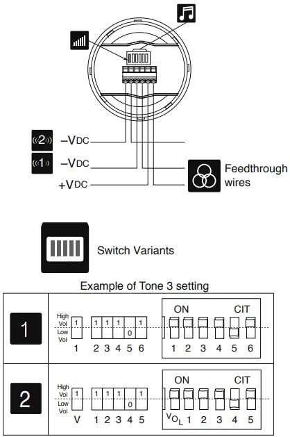
Siren tones
 |
|
Main Application | 24 V at 20 ºC | |||||
| Pattern | Frequency Hz | Rate | mA | dB(A) | ||||
| 1 | 14 | 11111 | Alternating | 800 and 970 | 2 Hz (250 ms-250 ms) | BS Fire | 68 | 100 |
| 2 | 14 | 11110 | Sweep | 800 to 970 | 7 Hz (7/s) | BS Fire | 68 | 101 |
| 3 | 14 | 11101 | Sweep | 800 to 970 | 1 Hz (1/s) | BS Fire | 68 | 101 |
| 4 | 14 | 11100 | Continuous | 2850 | Steady | General Purpose | 82 | 110 |
| 5 | 4 | 11011 | Sweep | 2400 to 2850 | 7 Hz | General Purpose | 80 | 110 |
| 6 | 4 | 11010 | Sweep | 2400 to 2850 | 1 Hz | General Purpose | 80 | 110 |
| 7 | 14 | 11001 | Slow whoop | 500 to 1200 | 3 s sweep, 0.5 s silence, then repeat | Dutch Fire (NEN 2575) | 70 | 98 |
| 8 | 14 | 11000 | Sweep (DIN) | 1200 to 500 | 1 Hz | German Fire (DIN 33 404) | 66 | 98 |
| 9 | 4 | 10111 | Alternating | 2400 and 2850 | 2 Hz (250 ms-250 ms) | General Purpose | 80 | 109 |
| 10 | 14 | 10110 | Intermittent | 970 | 0.5 Hz (1 s On/1 s Off) | PFEER alert | 62 | 100 |
| 11 | 14 | 10101 | Alternating | 800 and 970 | 1 Hz (500 ms-500 ms) | BS Fire | 68 | 100 |
| 12 | 4 | 10100 | Intermittent | 2850 | 0.5 Hz (1 s On/1 s Off) | General Purpose | 74 | 109 |
| 13 | 14 | 10011 | Intermittent | 970 | 0.8 Hz (250 ms On/1 s Off) | General Purpose | 58 | 96 |
| 14 | 14 | 10010 | Continuous | 970 | Steady | PFEER toxic gas | 70 | 101 |
| 15 | 14 | 10001 | Alternating | 554 and 440 | 100 ms-400 ms | French Fire (NFS 32-001) | 62 | 93 |
| 16 | 16 | 10000 | Intermittent | 660 | 3.3 Hz (150 ms On/150 ms Off) | Swedish (Air raid) | 59 | 86 |
| 17 | 17 | 01111 | Intermittent | 660 | 0.28 Hz (1.8 s On/1.8 s Off) | Swedish (Local warning) | 62 | 88 |
| 18 | 18 | 01110 | Intermittent | 660 | 0.05 Hz (13 s Off / 6.5 Hz On) | Swedish (Pre-mess) | 64 | 88 |
| 19 | 19 | 01101 | Continuous | 660 | Steady | Swedish (All clear) | 64 | 89 |
| 20 | 20 | 01100 | Alternating | 554 and 440 | 0.5 Hz (1 s On/1 s Off) | Swedish (Turn out) | 63 | 96 |
| 21 | 21 | 01011 | Intermittent | 660 | 1 Hz (500 ms-500 ms) | Swedish General Purpose | 60 | 100 |
| 22 | 14 | 01010 | Intermittent | 2850 | 4 Hz (150 ms On/100 ms Off) | Pelican crossing | 72 | 109 |
| 23 | 14 | 01001 | Sweep | 800 to 970 | 50 Hz | BS Fire | 68 | 101 |
| 24 | 4 | 01000 | Sweep | 2400 to 2850 | 50 Hz | General Purpose | 75 | 110 |
| 25 | 25 | 00111 | Intermittent | 970 | 3 x 500 ms pulses, 1.5 s silence, then repeat | ISO 8201 | 64 | 99 |
| 26 | 26 | 00110 | Intermittent | 800 to 970 | 3 x 500 ms pulsed sweep, 1.5 s silence, then repeat | ISO 8201 | 70 | 108 |
| 27 | 27 | 00101 | Intermittent | 970 and 800 | 3 x 500 ms pulsed sweep, 1.5 s silence, then repeat | ISO 8201 | 85 | 83 |
| 28 | 10 | 00100 | Alternating | 800 and 970 | 2 Hz (250 ms-250 ms) | BS Fire | 67 | 100 |
| 29 | 988 Hz | 00011 | Alternating | 990 and 650 | 2 Hz (250 ms-250 ms) (Symphoni tones) | BS Fire | 71 | 99 |
| 30 | 510 Hz | 00010 | Alternating | 510 and 610 | 2 Hz (250 ms-250 ms) (Squashni Micro tones) | BS Fire | 65 | 96 |
| 31 | 14 | 00001 | Sweep | 300 to 1200 | 1 Hz | General Purpose | 71 | 96 |
| 32 | 510 Hz | 00000 | Alternating | 510 and 610 | 1 Hz (500 ms-500 ms) | BS Fire | 85 | 83 |


