![]()
Installation manual
Split system air conditioners
CVXM20A2V1B, CVXM20A3V1B, FVXM25A2V1B
FVXM35A2V1B, FVXM50A2V1B, FVXM25A3V1B
FVXM35A3V1B, FVXM50A3V1B
About the documentation
About this document
![]() INFORMATION
INFORMATION
Make sure that the user has the printed documentation and ask him/her to keep it for future reference.
Target audience
Authorized installers![]() INFORMATION
INFORMATION
This appliance is intended to be used by expert or trained users in shops, in light industry, and on farms, or for commercial and household use by laypersons.
![]() WARNING
WARNING
Make sure installation, servicing, maintenance, repair, and applied materials follow the instructions from Daikin and, in addition, comply with applicable legislation and are performed by qualified persons only. In Europe and areas where IEC standards apply, EN/IEC 60335-2-40 is the applicable standard.
Documentation set
This document is part of a documentation set. The complete set consists of:
- General safety precautions:
- Safety instructions that you MUST read before installing
- Format: Paper (in the box of the indoor unit)
- Indoor unit installation manual:
- Installation instructions
- Format: Paper (in the box of the indoor unit)
- Installer reference guide:
- Preparation of the installation, good practices, reference data,…
- Format: Digital files on
http://www.daikineurope.com/support-and-manuals/product-information/
The latest revisions of the supplied documentation may be available on the regional Daikin website or via your dealer. The original documentation is written in English. All other languages are translations.
Technical engineering data
- A subset of the latest technical data is available on the regional Daikin website (publicly accessible).
- The full set of the latest technical data is available on the Daikin Business Portal (authentication required).
Specific installer safety instructions
Always observe the following safety instructions and regulations.
Unit installation (see “5 Unit installation” [4 4])![]() WARNING
WARNING
CVXM-A and FVXM-A Floor Standing range is allowed to be combined ONLY with systems with a total refrigerant amount <1.842 kg. Therefore in case of combination with outdoor units 3MXM40N8 or 3MXM52N8, the total liquid refrigerant piping length of the installation MUST be ≤30 m.
![]() WARNING
WARNING
The appliance shall be stored in a room without continuously operating ignition sources (for example open flames, an operating gas appliance, or an operating electric heater).![]() CAUTION
CAUTION
For walls containing a metal frame or a metal board, use a wall embedded pipe and wall cover in the feed-through hole to prevent possible heat, electrical shock, or fire.
Piping installation (see “6 Piping installation” [4 9])![]() DANGER: RISK OF BURNING/SCALDING
DANGER: RISK OF BURNING/SCALDING![]() CAUTION
CAUTION
- Use the flare nut fixed to the unit.
- To prevent gas leakage, apply refrigeration oil ONLY to the inside of the flare. Use refrigeration oil for R32.
- Do NOT reuse joints.
![]() CAUTION
CAUTION
- Do NOT use mineral oil on the flared part.
- NEVER install a drier to this R32 unit to guarantee its lifetime. The drying material may dissolve and damage the system.
![]() CAUTION
CAUTION
- Incomplete flaring may cause refrigerant gas leakage.
- Do NOT re-use flares. Use new flares to prevent refrigerant gas leakage.
- Use flare nuts that are included with the unit. Using different flare nuts may cause refrigerant gas leakage.
Electrical installation (see “7 Electrical installation” [4 10])
![]() DANGER: RISK OF ELECTROCUTION
DANGER: RISK OF ELECTROCUTION![]() WARNING
WARNING
- All wiring MUST be performed by an authorized electrician and MUST comply with the applicable legislation.
- Make electrical connections to the fixed wiring.
- All components procured on-site and all electrical construction MUST comply with the applicable legislation.
![]() WARNING
WARNING
- If the power supply has a missing or wrong N-phase, equipment might break down.
- Establish proper earthing. Do NOT earth the unit to a utility pipe, surge absorber, or telephone earth.
Incomplete earthing may cause electrical shock. - Install the required fuses or circuit breakers.
- Secure the electrical wiring with cable ties so that the cables do NOT come in contact with sharp edges or piping, particularly on the high-pressure side.
- Do NOT use taped wires, stranded conductor wires, extension cords, or connections from a star system.
They can cause overheating, electrical shock or fire. - Do NOT install a phase advancing capacitor, because this unit is equipped with an inverter. A phase-advancing capacitor will reduce performance and may cause accidents.
![]() WARNING
WARNING
ALWAYS use multicore cable for power supply cables.![]() WARNING
WARNING
Use an all-pole disconnection type breaker with at least 3 mm between the contact point gaps that provide full disconnection under overvoltage category III.![]() WARNING
WARNING
If the supply cord is damaged, it MUST be replaced by the manufacturer, its service agent or similarly qualified persons in order to avoid a hazard.![]() WARNING
WARNING
Do NOT connect the power supply to the indoor unit. This could result in electrical shock or fire.![]() WARNING
WARNING
- Do NOT use locally purchased electrical parts inside the product.
- Do NOT branch the power supply for the drain pump, etc. from the terminal block. This could result in electrical shock or fire.
![]() WARNING
WARNING
Keep the interconnection wiring away from copper pipes without thermal insulation as such pipes will be very hot.
About the box
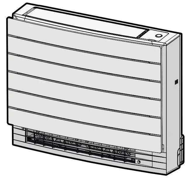
Indoor unit
3.1.1 To remove the accessories from the indoor unit
Remove the accessories located at the bottom of the package. A spare SSID sticker is located on the unit.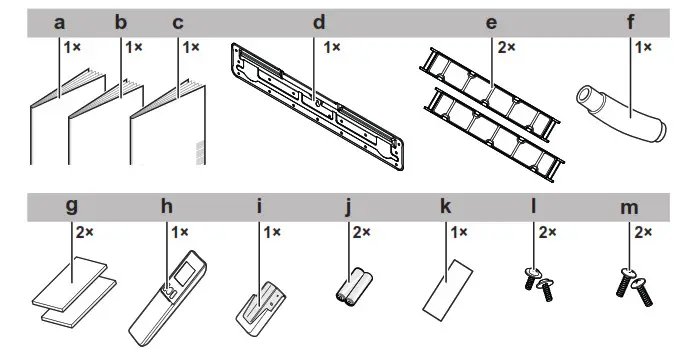
a. Installation manual
b. Operation manual
c. General safety precautions
d. Mounting plate (attached to the unit)
e. Titanium apatite deodorizing filter
f. Drain hose
g. Insulation piece
h. User interface
i. User interface holder
j. Dry battery AAA.LR03 (alkaline) for user interface
k. Spare SSID sticker (attached to the unit)
l. Screws for fixing drain hose
m. Whitehead screws “8.2.2 To re-install the front grille” [4 11]
- Spare SSID sticker.
Do NOT throw away the spare sticker. Keep it in a safe place in case it is needed in the future (e.g. in case the front grille is replaced, attach it to the new front grille).
About the unit
 WARNING: MILDLY FLAMMABLE MATERIAL
The refrigerant inside this unit is mildly flammable.
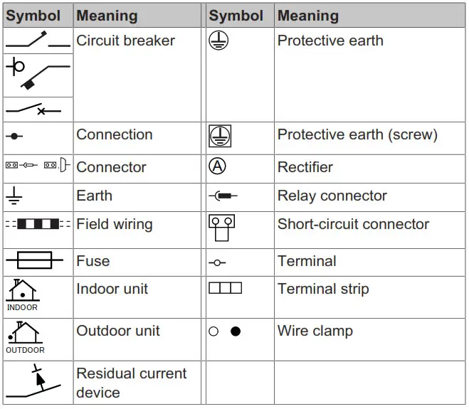
Following symbols may occur on the indoor unit:
| Symbol | Explanation |
 | Measure the voltage at the terminals of the main circuit capacitors or electrical components before servicing. |
About the wireless LAN
For detailed specifications, installation instructions, setting methods, FAQ, declaration of conformity, and the latest version of this manual, visit app.daikineurope.com.

![]() INFORMATION
INFORMATION
- Daikin Industries Czech Republic s.r.o. declares that the radio equipment type inside of this unit is in compliance with Directive 2014/53/EU.
- This unit is considered as combined equipment according to the definition of Directive 2014/53/EU.
4.1.1 Precautions when using the wireless LAN
Do NOT use near:
- Medical equipment. E.g. persons using cardiac pacemakers or defibrillators. This product may cause electromagnetic interference.
- Auto-control equipment. E.g. automatic doors or fire alarm equipment. This product may cause faulty behavior of the equipment.
- Microwave oven. It may affect wireless LAN communications.
4.1.2 Basic parameters
| What | Value |
| Frequency range | 2400 MHz~2483.5 MHz |
| Radio protocol | IEEE 802.11b/g/n |
| Radiofrequency channel | 13ch |
| Output power | 13 dBm |
| Effective radiated power | 15 dBm (11b) / 14 dBm (11g) /14 dBm (11n) |
| Power supply | DC 14 V / 100 mA |
4.1.3 Setting the wireless LAN
The customer is responsible for providing:
- Smartphone or tablet with minimum supported version of Android or iOS, specified on app.daikineurope.com
- Internet line and communicating device, such as modem, router, etc.
- Wireless LAN access point.
- Installed free Daikin Residential Controller application.
To install the Daikin Residential Controller application
- Open:
▪ Google Play for appliances using Android.
▪ App Store for appliances using iOS. - Search for Daikin Residential Controller.
- Follow the directions on the screen to install.
Unit installation
Preparing the installation site
![]() WARNING
WARNING
The appliance shall be stored in a room without continuously operating ignition sources (example: open flames, an operating gas appliance or an operating electric heater).
5.1.1 Installation site requirements of the indoor unit![]() INFORMATION
INFORMATION
The sound pressure level is less than 70 dBA.![]() WARNING
WARNING
CVXM-A and FVXM-A Floor Standing range is allowed to be combined ONLY with systems with a total refrigerant amount <1.842 kg. Therefore in case of combination with outdoor units 3MXM40N8 or 3MXM52N8, the total liquid refrigerant piping length of the installation MUST be ≤30 m.
- Spacing. Mind the following requirements:

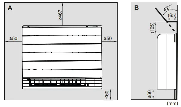
A. Front view
B. Side view
- Do not install the unit more than 60 mm above the floor.
- Wall insulation. When conditions in the wall exceed 30°C and relative humidity of 80%, or when fresh air is inducted into the wall, then additional insulation is required (minimum 10 mm thickness, polyethylene foam).
- Wall or floor strength. Check whether the wall or the floor is strong enough to support the weight of the unit. If there is a risk, reinforce the wall or the floor before installing the unit.
Opening the indoor unit
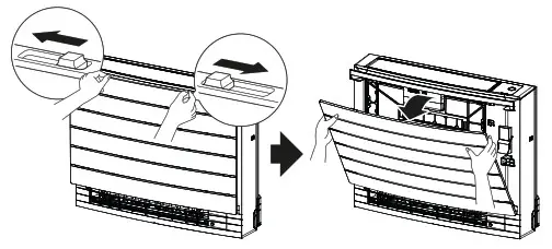
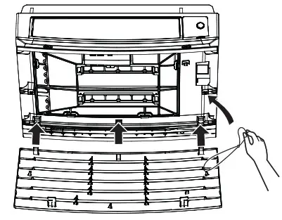
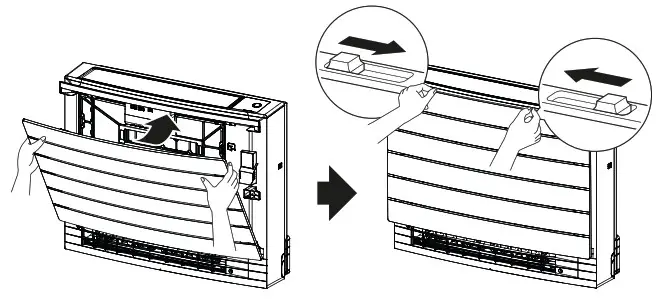
5.2.1 To remove the front panel
- Slide both sliders in the direction of the arrows until they click.

- Open the front panel and remove the string.

- Remove the front panel.
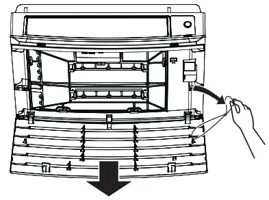
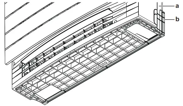
5.2.2 To remove the front grille
- Remove the front panel. See “5.2.1 To remove the front panel” [4 4].
- Remove the 4 screws, remove the grille from 4 tabs on the top and remove the front grille while pulling it toward you.

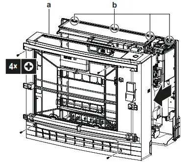
a. Front grille
b. Tabs
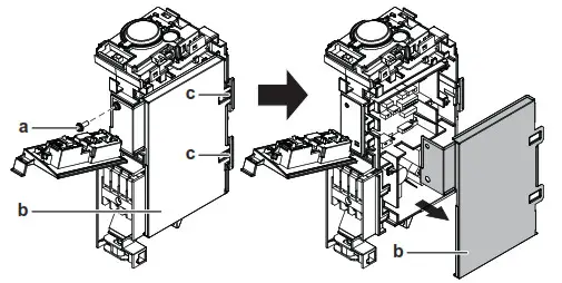
5.2.3 To open the terminal block and remove the electrical wiring box cover
To open the terminal block
- Remove the front grille.
- Remove 1 lower screw.
- Lift the sensor securing plate.
- Move the metal plate cover down and then towards you to remove it.
a. Screw
b. Sensor securing plate
c. Metal plate cover
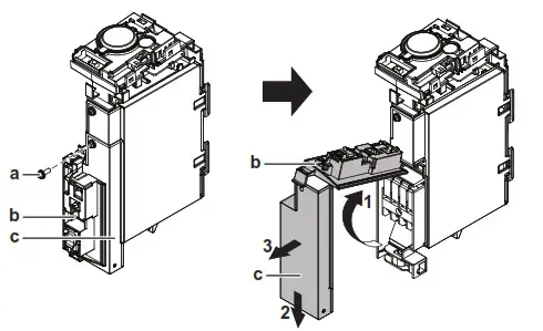
To remove the electrical wiring box cover
- Open the terminal block.
- Remove 1 screw from the electrical wiring box.
- Unhook the 2 tabs on the electrical wiring box cover and remove it.

a. Screw
b. Wiring box cover
c. Tabs
Mounting the indoor unit
5.3.1 To install the indoor unit
Installation options
There are 3 possible type of installation for the indoor unit.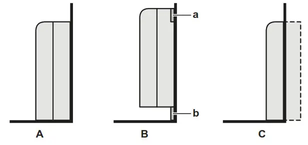
A. Floor (exposed) installation
B. Wall (exposed) installation
C. Half concealed installation
a. Mounting plate
b. Skirting board
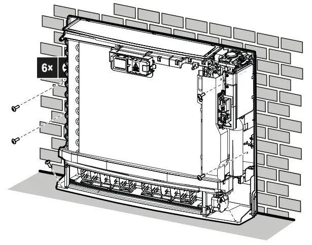
Unit installation
Floor-standing installation
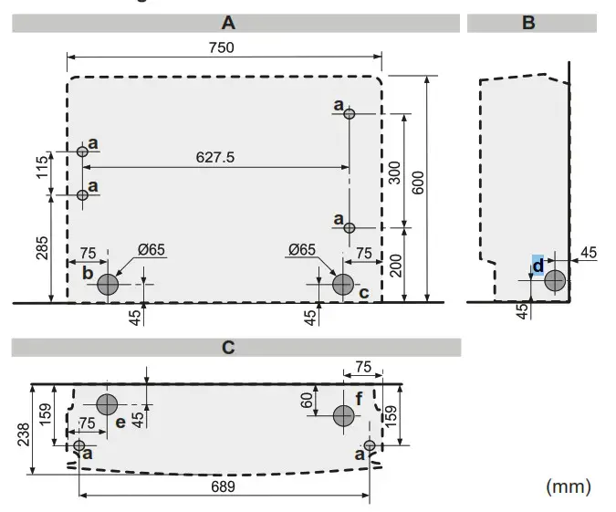
5‒1 Indoor unit installation drawing: Floor-standing installation
A. Front view
B. Side view
C. Top view
a. Screw hole 6×
b. Left-back piping hole location
c. Right-back piping hole location
d. Left/right piping hole location
e. Left-bottom piping hole location
f. Right-bottom piping hole location
- Drill a wall hole, depending on which side piping is taken out.
See “5.3.2 To drill a wall hole” [4 8]. - Open the front panel and remove the front grille (see “5.2 Opening the indoor unit” [4 4]).
- Remove the slit portions using nippers. See “5.3.3
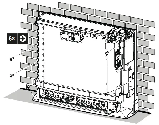
To remove the slit portions” [4 8]. - Secure the unit to the wall and floor using 6 screws M4×25L (field supply).

- When the complete installation is finished, attach the front panel and the front grille in their original position.
Wall-mounted installation
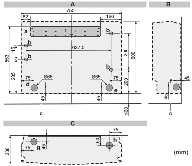
5‒2 Indoor unit installation drawing: Wall-mounted installation
A. Front view
B. Side view
C. Top view
a. Mounting plate
b. Screw hole 4×
c. Floor
d. Left-back piping hole location
e. Right-back piping hole location
f. Left/right piping hole location
g. Left-bottom piping hole location
h. Right-bottom piping hole location - Temporarily secure the mounting plate on the wall.
- Make sure the mounting plate is level.
- Mark the centers of the drilling points on the wall.
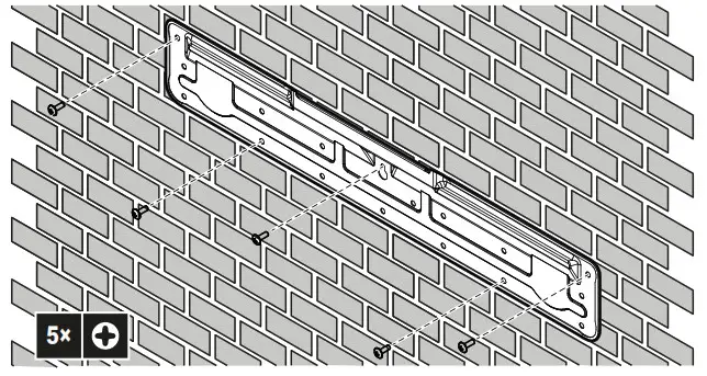
- Secure the mounting plate on the wall using 5 screws M4×25L (field supply).

- Drill a wall hole, depending on which side piping is taken out.
See “5.3.2 To drill a wall hole” [4 8]. - Open the front panel and remove the front grille (see “5.2 Opening the indoor unit” [4 4]).
- Remove the slit portions using nippers. See “5.3.3
To remove the slit portions” [4 8]. - If necessary for the skirting board, remove the slit portion on the bottom frame.

a. Bottom frame
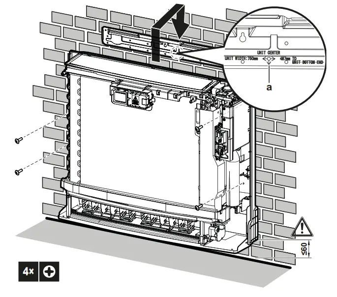
b. Slit portion - Align the unit using the alignment symbol
 on the mounting plate: 375 mm from the alignment symbol to each side (unit width 750 mm), 487 mm from the alignment symbol to the bottom of the unit.
 - Hook the unit on the mounting plate and secure the unit to the wall using 4 screws M4×25L (field supply).
 a. Alignment symbol
 - When the complete installation is finished, attach the front panel and the front grille in their original position.
Half-concealed installation
5‒3 Indoor unit installation drawing: Half-concealed installation
A. Front view
B. Side view
C. Top view
a. Extra filler board
b. Screw hole 6×
c. Hole
d. Left-back piping hole location
e. Right-back piping hole location
f. Right/left piping hole location
g. Left-bottom piping hole location
h. Right-bottom piping hole location - Make a hole in the wall as illustrated above.
- Install the extra filler board (field supply) in accordance with the space between the unit and the wall. Make sure there is no gap between the unit and the wall.
- Drill a wall hole, depending on which side piping is taken out. See “5.3.2 To drill a wall hole” [4 8].
- Remove the slit portions using nippers. See “5.3.3 To remove the slit portions” [4 8].
- Open the front panel, remove the front grille, remove the top and side casings (see “5.2 Opening the indoor unit” [4 4]).
- Secure the unit to the extra filler board and to the floor using 6 screws M4×25L (field supply).

- When the complete installation is finished, attach the front panel and the front grille in their original position.
 a. Alignment symbol
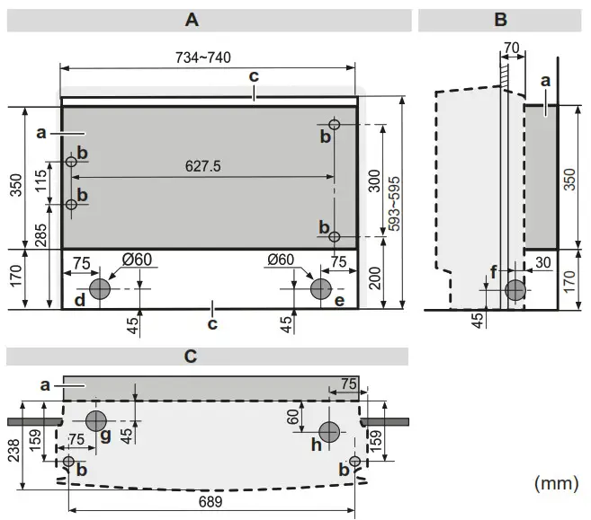
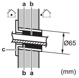
5.3.2 To drill a wall hole![]() CAUTION
CAUTION
For walls containing a metal frame or a metal board, use a wall embedded pipe and wall cover in the feed-through hole to prevent possible heat, electrical shock, or fire.![]() NOTICE
NOTICE
Be sure to seal the gaps around the pipes with a sealing material (field supply), in order to prevent water leakage.
- Bore a 65 mm large feed-through hole in the wall with a downward slope towards the outside.
- Insert a wall-embedded pipe into the hole.
- Insert a wall cover into the wall pipe.

a. Wall-embedded pipe
b. Putty
c. Wall hole cover - After completing wiring, refrigerant piping, and drain piping, do NOT forget to seal the gap with putty.
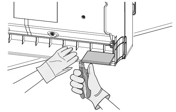
5.3.3 To remove the slit portions
For side piping (left/right) and bottom piping (left/right) slit portions must be removed. Remove slit portions according to where the piping is taken out.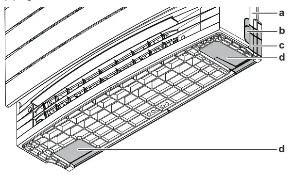
a. Bottom frame
b. Slit portion for side piping on the front grille (same on the other side)
c. Slit portion for side piping on the bottom frame (same of the other side)
d. Slit portion for the bottom piping
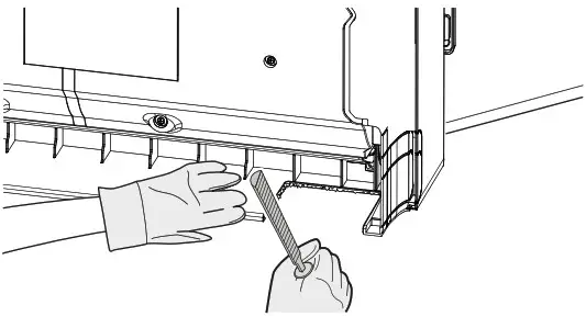
- Cut off the slit portion using nippers.

- Remove burrs along the cut section using a half-round needle file.

5.3.4 To provide drainage
Make sure condensation water can be evacuated properly. This involves:
- General guidelines
- Connecting the drain piping to the indoor unit
- Checking for water leaks
General guidelines
- Pipe length. Keep drain piping as short as possible.
- Pipe size. Use rigid polyvinyl chloride pipe with 20 mm nominal diameter and 26 mm outer diameter.
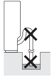
![]() NOTICE
NOTICE
- Install the drain hose with a downward slope.
- Traps are NOT permitted.
- Do NOT put the end of the hose in water.
- Drain hose. The drain hose (accessory) is 220 mm long and with 18 mm outer diameter on the connecting side.
- Extension hose. Use rigid polyvinyl chloride pipe (field supply) with 20 mm nominal diameter as an extension hose. When connecting an extension hose, use a polyvinyl adhesive agent for gluing.
- Condensation. Take measures against condensation. Insulate the complete drain piping in the building.
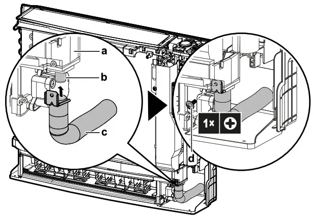
To connect the drain piping to the indoor unit![]() NOTICE
NOTICE
Incorrect connection of the drain hose might cause leaks, and damage the installation space and surroundings.
- Push the drain hose (accessory) as far as possible over the drain socket and fix it with 1 screw (accessory).

a. Drain pan
b. Drain socket
c. Drain hose (accessory)
d. Screw (accessory) - Check for water leaks (see “To check for water leaks” [4 9]).
- Insulate the indoor drain socket and drain hose with ≥10 mm insulation material to prevent condensation.
- Connect the drain piping to the drain hose. Insert the drain hose ≥50 mm, so it will not be pulled out of the drain pipe.

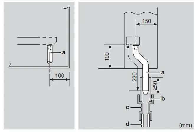
a. Drain hose (accessory)
b. Vinyl chloride drain pipe (VP-30) (field supply)
c. Reducer (field supply)
d. Vinyl chloride drain pipe (VP-20) (field supply)
To check for water leaks
- Remove the air filters.
- Gradually pour approximately 1 l of water into the drain pan, and check for water leaks.

Piping installation
Preparing refrigerant piping
6.1.1 Refrigerant piping requirements
NOTICE
The piping and other pressure-containing parts shall be suitable for the refrigerant. Use phosphoric acid deoxidized seamless copper for the refrigerant.
INFORMATION
Additional refrigerant charge is NOT allowed in case of a combination of the outdoor unit 3MXM40N8 or 3MXM52N8 with the indoor units CVXM-A and/or FVXM-A. The total piping length MUST be ≤30 m.
- Foreign materials inside pipes (including oils for fabrication) must be ≤30 mg/10 m.
Refrigerant piping diameter
Use the same diameters as the connections on the outdoor units:
| Class | Pipe outer diameter (mm) | |
| Liquid piping | Gas piping | |
| 20~35 | Ø6.4 | Ø9.5 |
| 50 | Ø6.4 | Ø12.7 |
Refrigerant piping material
- Piping material: Phosphoric acid deoxidized seamless copper.
- Piping temper grade and thickness:
| Outer diameter (Ø) | Temper grade | Thickness (t)(a) | |
| 6.4 mm (1/4″) | Annealed (O) | ≥0.8 mm | 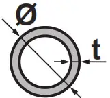 |
| 9.5 mm (3/8″) | |||
| 12.7 mm (1/2″) | |||
(a) Depending on the applicable legislation and the maximum working pressure of the unit (see “PS High” on the unit nameplate), a larger piping thickness might be required.
6.1.2 Refrigerant piping insulation
- Use polyethylene foam as an insulation material:
- with a heat transfer rate between 0.041 and 0.052 W/mK (0.035 and 0.045 kcal/mh°C)
- with a heat resistance of at least 120°C
- Insulation thickness
| Pipe outer diameter (Øp) | Insulation inner diameter (Ø) | Insulation thickness (t) |
| 6.4 mm (1/4″) | 8~10 mm | ≥10 mm |
| 9.5 mm (3/8″) | 12~15 mm | ≥13 mm |
| 12.7 mm (1/2″) | 14~16 mm | ≥13 mm |

If the temperature is higher than 30°C and the humidity is higher than RH 80%, the thickness of the insulation materials should be at least 20 mm to prevent condensation on the surface of the insulation.
Electrical installation
Connecting the refrigerant piping
DANGER: RISK OF BURNING/SCALDING
6.2.1 To connect the refrigerant piping to the indoor unit
WARNING: MILDLY FLAMMABLE MATERIAL
The refrigerant inside this unit is mildly flammable.
- Pipe length. Keep refrigerant piping as short as possible.
- Connect refrigerant piping to the unit using flare connections.
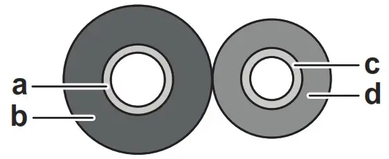
- Insulate the refrigerant piping on the indoor unit as follows:

a. Gas pipe
b. Gas pipe insulation
c. Liquid pipe
d. Liquid pipe insulation NOTICE
Make sure to insulate all refrigerant piping. Any exposed piping might cause condensation. - Close the slit on the refrigerant pipe connection and secure it with a tape (field supply). Make sure there are no gaps.
- Wrap the slit and the end of the insulation of the connected refrigerant piping with an insulation piece (accessory). Make sure there are no gaps.

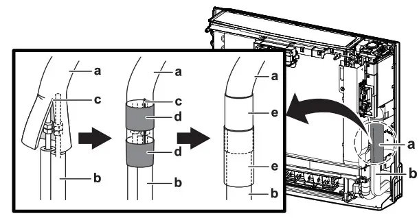
a. Refrigerant pipe connection
b. Refrigerant piping (field supply)
c. Slit
d. Tape
e. Insulation piece (accessory)
Electrical installation
![]() DANGER: RISK OF ELECTROCUTION
DANGER: RISK OF ELECTROCUTION ![]() WARNING
WARNING
ALWAYS use multicore cable for power supply cables.![]() WARNING
WARNING
Use an all-pole disconnection type breaker with at least 3 mm between the contact point gaps that provide full disconnection under overvoltage category III.![]() WARNING
WARNING
If the supply cord is damaged, it MUST be replaced by the manufacturer, its service agent or similarly qualified persons in order to avoid a hazard.
![]() WARNING
WARNING
Do NOT connect the power supply to the indoor unit. This could result in electrical shock or fire.![]() WARNING
WARNING
- Do NOT use locally purchased electrical parts inside the product.
- Do NOT branch the power supply for the drain pump, etc. from the terminal block. This could result in electrical shock or fire.
![]() WARNING
WARNING
Keep the interconnection wiring away from copper pipes without thermal insulation as such pipes will be very hot.
Specifications of standard wiring components
| Component | 4-core cable 1.5 mm²~2.5 mm² and applicable for 220~240 V H05RN-F (60245 IEC 57) |
| Interconnection cable (indoor↔outdoor) |
To connect the electrical wiring to the indoor unit
- Open the terminal block. See “5.2 Opening the indoor unit” [4 4].
- Strip the wire ends approximately 15 mm.
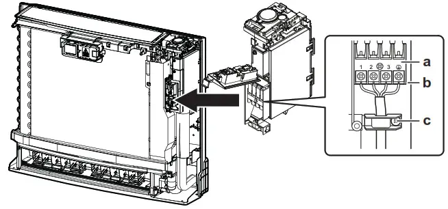
- Match wire colors with terminal numbers on indoor and outdoor unit’s terminal blocks and firmly screw wires to the corresponding terminals.
- Connect the earth wires to the corresponding terminals.

a. Terminal block
b. Electrical component block
c. Cable clamp - Pull the wires to make sure that they are securely attached, then retain the wires with the cable clamp.
- Make sure that the wires do not come in contact with the metal parts of the heat exchanger.
- In case of connecting to an optional adapter, see “7.3 To connect optional accessories (wired user interface, central user interface, wireless adapter, etc.)” [4 11].

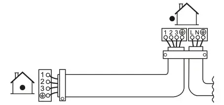
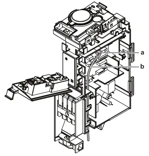
To connect optional accessories (wired user interface, central user interface, wireless adapter, etc.)
- Remove the electrical wiring box cover. See “5.2 Opening the indoor unit” [4 4].
- Connect the optional adapter wire to the S21 connector. To connect the optional adapter wire to the option, refer to the installation manual of the optional adapter.
- Lead the wire as shown in the figure below.

a. S21 connector
b. Optional adapter wire - Close the electrical wiring box cover. See “8.2 To close the indoor unit” [4 11].
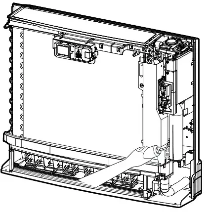
Finishing the indoor unit installation
To finish the indoor unit installation
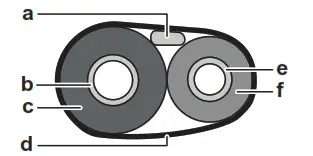
- After the drain piping, refrigerant piping and electrical wiring are finished. Wrap the refrigerant pipes and the interconnection cable with insulation tape. They overlap at least half the width of the tape with each turn.

a. Interconnection cable
b. Gas pipe
c. Gas pipe insulation
d. Insulation tape
e. Liquid pipe
f. Liquid pipe insulation - Pass the pipes through the wall hole and seal the gaps with putty.
To close the indoor unit
8.2.1 To close the electrical wiring box and close the terminal block
- Hook the electrical wiring box onto the 2 tabs, close it, and fix it with 1 screw.
- Attach the front metal cover and fix it with the screw.
- Close the sensor securing plate.
8.2.2 To re-install the front grille
- Attach the front grille to the original position.
- Secure the front grille in 4 tabs.
- Secure with the 2 original screws on the top part and with the 2 white head screws (accessory) on the bottom part.

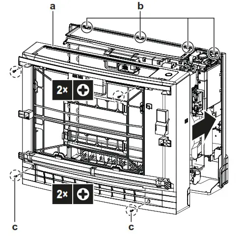
a. Front grille
b. 4 tabs
c. Whitehead screws (accessory)
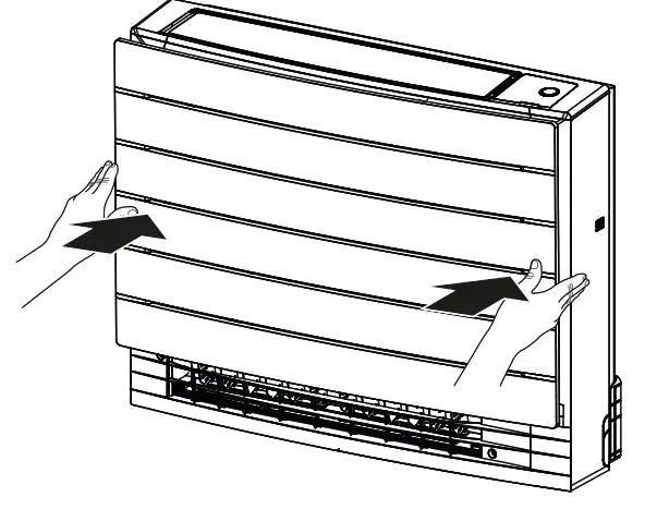
8.2.3 To re-install the front panel
- Insert the front panel into the grooves of the unit (3 places) and attach the string.

- Close the front panel and slide both sliders until they click.

Commissioning
![]() NOTICE
NOTICE
ALWAYS operate the unit with thermistors and/or pressure sensors/switches. If NOT, burning of the compressor might be the result.
To perform a test run
Prerequisite: Power supply MUST be in the specified range.
Prerequisite:
Test run may be performed in cooling or heating mode.
Prerequisite:
Test run should be performed in accordance with the operation manual of the indoor unit to make sure that all functions and parts are working properly.
- In cooling mode, select the lowest programmable temperature.
In heating mode, select the highest programmable temperature.
A test run can be disabled if necessary. - When the test run is finished, set the temperature to a normal level. In cooling mode: 26~28°C, in heating mode: 20~24°C.
- The system stops operating 3 minutes after the unit is turned OFF.
9.1.1 To perform a test run using the user interface
- Press
 to switch the system on.
 - Press the middle ∧Temp∨ of Mode and simultaneously.
- Press Temp∨ twice to 7 choose and confirm the selection by pressing Mode.
Result: 7 on the display indicates that the test run is selected. Test run operation will stop automatically after about 30 minutes. - To stop operation sooner, press the ON/OFF button.
Disposal
![]() NOTICE
NOTICE
Do NOT try to dismantle the system yourself: the dismantling of the system, treatment of the refrigerant, oil and other parts MUST comply with applicable legislation. Units MUST be treated at a specialized treatment facility for reuse, recycling, and recovery.
Technical data
- A subset of the latest technical data is available on the regional Daikin website (publicly accessible).
- The full set of the latest technical data is available on the Daikin Business Portal (authentication required).
Wiring diagram
11.1.1 Unified wiring diagram legend
For applied parts and numbering, refer to the wiring diagram on the unit. Part numbering is by Arabic numbers in ascending order for each part and is represented in the overview below by “*” in the part code.
| Symbol | Colour | Symbol | Colour |
| BLK | Black | ORG | Orange |
| BLU | Blue | PNK | Pink |
| BRN | Brown | PRP, PPL | Purple |
| GRN | Green | RED | Red |
| GRY | Grey | WHT | White |
| YLW | Yellow |
| Symbol | Meaning |
| AP | Printed circuit board |
| BS* | Pushbutton ON/OFF, an operation switch |
| BZ, H*0 | Buzzer |
| C* | Capacitor |
| AC*, CW, E*, HA*, HE*, HL’, HN*, HR*, MICA, MICB, V, U, V, W, rA, K*122, NE | Connection, connector |
| D*, WD | Diode |
| Dr | Diode bridge |
| DS* | DIP switch |
| EH | Heater |
| FU’, PU, (for characteristics, refer to PCB inside your unit) | Fuse |
| FG* | Connector (frame ground) |
| 1-1* | Harness |
| HP, LED•, VI_ | Pilot lamp, light-emitting diode |
| HAP | Light-emitting diode (service monitor green) |
| HIGH VOLTAGE | High voltage |
| IES | Intelligent eye sensor |
| IPM* | Intelligent power module |
| K*R, KCR, KFR, KHuR, K*M | Magnetic relay |
| L | Live |
| Symbol | Meaning |
| L’ | Coil |
| L’R | Reactor |
| M’ | Stepper motor |
| WC | Compressor motor |
| WF | Fan motor |
| WP | Drain pump motor |
| WS | Swing motor |
| MR’, MRCVV, MRM’, MRN’ | Magnetic relay |
| N | Neutral |
| n=’, N=” | Number of passes through ferrite core |
| PAM | Pulse-amplitude modulation |
| PCB’ | Printed circuit board |
| PM’ | Power module |
| PS | Switching power supply |
| PTC’ | PTC thermistor |
| CI’ | Insulated gate bipolar transistor (IGBT) |
| at | Circuit breaker |
| CM!, KLM | Earth leak circuit breaker |
| Q’L | Overload protector |
| CrM | Thermo switch |
| O’R | Residual current device |
| R’ | Resistor |
| R’T | Thermistor |
| RC | Receiver |
| St | Limit switch |
| S’L | Float switch |
| VNG | Refrigerant leak detector |
| S’NPH | Pressure sensor (high) |
| S’NPL | Pressure sensor (low) |
| VPH, HPS` | Pressure switch (high) |
| S’PL | Pressure switch (low) |
| VT | Thermostat |
| VRH | Humidity sensor |
| VW, SW’ | Operation switch |
| SR, F1S | Surge arrester |
| SR*, WLU | Signal receiver |
| SS* | Selector switch |
| SHEET METAL | Terminal strip fixed plate |
| rR | Transformer |
| TC, TRC | Transmitter |
| V’, KV | Varistor |
| V’R | Diode bridge, Insulated-gate bipolar transistor (IGBT) power module |
| WRC | Wireless remote controller |
| X’ | Terminal |
| X’M | Terminal strip (block) |
| Y’E | Electronic expansion valve coil |
| Y’R, Y’S | Reversing solenoid valve coil |
| Zit | Ferrite core |
| ZF, Z’F | Noise filter |
CVXM20A + FVXM25~50A
Split system air conditioners
3P477070-2M – 2021.09

DAIKIN INDUSTRIES CZECH REPUBLIC s.r.o.
U Nove Flospody 111155, 301 00 Plzen Skyrnany, Czech Republic
DAIKIN EUROPE N.V.
Zandvomdestraat 300, B-8400 Oostende, Belgium
3P477070-2M 2021.09
Copyright 2020 Daikin


