![]()
Installation manual
R32 Split system air conditioners
| RXJ20M5V1B | RXJ20M5V1B9 |
| RXJ25M5V1B | RXJ25M5V1B9 |
| RXJ35M5V1B | RXJ35M5V1B9 |
| RXA20A5V1B | RXA20A5V1B9 |
| RXA25A5V1B | RXA25A5V1B9 |
| RXA35A5V1B | RXA35A5V1B9 |
| RXM20R5V1B | RXM20R5V1B9 |
| RXM25R5V1B | RXM25R5V1B9 |
| RXM35R5V1B | RXM35R5V1B9 |
| ARXM25R5V1B | ARXM25R5V1B9 |
| ARXM35R5V1B | ARXM35R5V1B9 |
About the documentation
About this document
Target audience
Authorised installers
![]() WARNING
WARNING
Make sure installation, servicing, maintenance, repair and applied materials follow the instructions from Daikin and, in addition, comply with applicable legislation and are performed by qualified persons only. In Europe and areas where IEC standards apply, EN/IEC 60335-2-40 is the applicable standard.
![]() INFORMATION
INFORMATION
This document only describes installation instructions specific to the outdoor unit. For installation of the indoor unit (mounting the indoor unit, connecting the refrigerant piping to the indoor unit, connecting the electrical wiring to the indoor unit …), see the installation manual of the indoor unit.
Documentation set
This document is part of a documentation set. The complete set consists of:
▪ General safety precautions:
▪ Safety instructions that you MUST read before installing
▪ Format: Paper (in the box of the outdoor unit)
▪ Outdoor unit installation manual:
▪ Installation instructions
▪ Format: Paper (in the box of the outdoor unit)
▪ Installer reference guide:
▪ Preparation of the installation, reference data,…
▪ Format: Digital files on http://www.daikineurope.com/support-and-manuals/product-information/
Latest revisions of the supplied documentation may be available on the regional Daikin website or via your dealer.
The original documentation is written in English. All other languages are translations.
Technical engineering data
- A subset of the latest technical data is available on the regional Daikin website (publicly accessible).
- The full set of latest technical data is available on the Daikin Business Portal (authentication required).
Specific installer safety instructions
Always observe the following safety instructions and regulations.
Unit installation (see “4 Unit installation” [4 7])
![]() WARNING
WARNING
Installation shall be done by an installer, the choice of materials and installation shall comply with the applicable legislation. In Europe, EN378 is the applicable standard.
Installation site (see “4.1 Preparing the installation site” [4 7])
![]() CAUTION
CAUTION
- Check if the installation location can support the unit’s weight. Poor installation is hazardous. It can also cause vibrations or unusual operating noise.
- Provide sufficient service space.
- Do NOT install the unit so that it is in contact with a ceiling or a wall, as this may cause vibrations.
![]() WARNING
WARNING
The appliance shall be stored in a room without continuously operating ignition sources (example: open flames, an operating gas appliance or an operating electric heater).
Connecting the refrigerant piping (see “5.2 Connecting the refrigerant piping” [4 9])
![]() CAUTION
CAUTION
- No brazing or welding on site for units with R32 refrigerant charge during shipment.
- During installation of the refrigeration system, joining of parts with at least one part charged shall be performed taking into account the following requirements: inside occupied spaces non permanent joints are not allowed for R32 refrigerant except for site made joints directly connecting the indoor unit to piping. Site made joints directly connecting piping to indoor units shall be of non permanent type.
![]() CAUTION
CAUTION
- Use the flare nut fixed to the unit.
- To prevent gas leakage, apply refrigeration oil only to the inside of the flare. Use refrigeration oil for R32.
- Do NOT reuse joints.
![]() CAUTION
CAUTION
- Do NOT use mineral oil on flared part.
- Do NOT reuse piping from previous installations.
- NEVER install a drier to this R32 unit to guarantee its lifetime. The drying material may dissolve and damage the system.
![]() WARNING
WARNING
Connect the refrigerant piping securely before running the compressor. If the refrigerant piping is NOT connected and the stop valve is open when the compressor is run, air will be sucked in. This will cause abnormal pressure in the refrigeration cycle, which may result in equipment damage and even injury.
![]() CAUTION
CAUTION
- Incomplete flaring may cause refrigerant gas leakage.
- Do NOT re-use flares. Use new flares to prevent refrigerant gas leakage.
- Use flare nuts that are included with the unit. Using different flare nuts may cause refrigerant gas leakage.
![]() CAUTION
CAUTION
Do NOT open the valves before flaring is complete. This would cause refrigerant gas leakage.![]() DANGER: RISK OF EXPLOSION
DANGER: RISK OF EXPLOSION
Do NOT start the unit if it is vacuumed.
Charging refrigerant (see “6 Charging refrigerant” [4 10])
![]() WARNING
WARNING
The refrigerant inside the unit is mildly flammable, but normally does NOT leak. If the refrigerant leaks in the room and comes in contact with fire from a burner, a heater, or a cooker, this may result in fire, or the formation of a harmful gas. Turn off any combustible heating devices, ventilate the room, and contact the dealer where you purchased the unit. Do NOT use the unit until a service person confirms that the part from which the refrigerant leaked has been repaired.
![]() WARNING
WARNING
- Only use R32 as refrigerant. Other substances may cause explosions and accidents.
- R32 contains fluorinated greenhouse gases. Its global warming potential (GWP) value is 675. Do NOT vent these gases into the atmosphere.
- When charging refrigerant, ALWAYS use protective gloves and safety glasses.
![]() CAUTION
CAUTION
To avoid compressor breakdown, do NOT charge more than the specified amount of refrigerant.![]() WARNING
WARNING
NEVER directly touch any accidental leaking refrigerant. This could result in severe wounds caused by frostbite.
Electrical installation (see “7 Electrical installation” [4 11])![]() WARNING
WARNING
Appliance shall be installed in accordance with national wiring regulations.
![]() WARNING
WARNING
- All wiring MUST be performed by an authorised electrician and MUST comply with the applicable legislation.
- Make electrical connections to the fixed wiring.
- All components procured on-site and all electrical construction MUST comply with the applicable legislation.
![]() WARNING
WARNING
- If the power supply has a missing or wrong N-phase, equipment might break down.
- Establish proper earthing. Do NOT earth the unit to a utility pipe, surge absorber, or telephone earth. Incomplete earthing may cause electrical shock.
- Install the required fuses or circuit breakers.
- Secure the electrical wiring with cable ties so that the cables do NOT come in contact with sharp edges or piping, particularly on the high-pressure side.
- Do NOT use taped wires, stranded conductor wires, extension cords, or connections from a star system. They can cause overheating, electrical shock or fire.
- Do NOT install a phase advancing capacitor, because this unit is equipped with an inverter. A phase advancing capacitor will reduce performance and may cause accidents.
![]() WARNING
WARNING
ALWAYS use multicore cable for power supply cables.![]() WARNING
WARNING
Use an all-pole disconnection type breaker with at least 3 mm between the contact point gaps that provide full disconnection under overvoltage category III.![]() WARNING
WARNING
If the supply cord is damaged, it MUST be replaced by the manufacturer, its service agent or similarly qualified persons in order to avoid a hazard.![]() WARNING
WARNING
Do NOT connect the power supply to the indoor unit. This could result in electrical shock or fire.![]() WARNING
WARNING
- Do NOT use locally purchased electrical parts inside the product.
- Do NOT branch the power supply for the drain pump, etc. from the terminal block. This could result in electrical shock or fire.
![]() WARNING
WARNING
Keep the interconnection wiring away from copper pipes without thermal insulation as such pipes will be very hot.![]() DANGER: RISK OF ELECTROCUTION
DANGER: RISK OF ELECTROCUTION
All electrical parts (including thermistors) are powered by the power supply. Do not touch them with bare hands.![]() DANGER: RISK OF ELECTROCUTION
DANGER: RISK OF ELECTROCUTION
Disconnect the power supply for more than 10 minutes, and measure the voltage at the terminals of main circuit capacitors or electrical components before servicing. The voltage MUST be less than 50 V DC before you can touch electrical components. For the location of the terminals, see the wiring diagram.
Finishing indoor unit installation (see “8 Finishing the outdoor unit installation” [4 12])
![]() DANGER: RISK OF ELECTROCUTION
DANGER: RISK OF ELECTROCUTION
- Make sure that the system is earthed properly.
- Turn off the power supply before servicing.
- Install the switch box cover before turning on the power supply.
Commissioning (see “10 Commissioning” [4 13])
![]() DANGER: RISK OF ELECTROCUTION
DANGER: RISK OF ELECTROCUTION![]() DANGER: RISK OF BURNING/SCALDING
DANGER: RISK OF BURNING/SCALDING![]() CAUTION
CAUTION
Do NOT perform the test operation while working on the indoor units.
When performing the test operation, NOT only the outdoor unit, but the connected indoor unit will operate as well.
Working on an indoor unit while performing a test operation is dangerous.![]() CAUTION
CAUTION
Do NOT insert fingers, rods or other objects into the air inlet or outlet. Do NOT remove the fan guard. When the fan is rotating at high speed, it will cause injury.
About the box
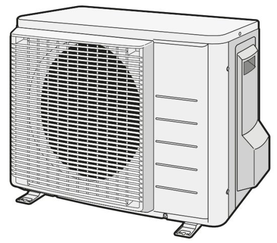
Outdoor unit
To remove the accessories from the outdoor unit
- Lift the outdoor unit.
- Remove the accessories at the bottom of the package.

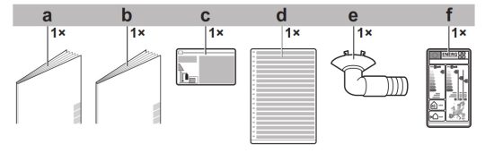
a. General safety precautions
b. Outdoor unit installation manual
c. Fluorinated greenhouse gases label
d. Multilingual fluorinated greenhouse gases label
e. Drain plug (located on the bottom of the packing case)
f. Energy label
Unit installation
![]() WARNING
WARNING
Installation shall be done by an installer, the choice of materials and installation shall comply with the applicable legislation. In Europe, EN378 is the applicable standard.
Preparing the installation site
![]() WARNING
WARNING
The appliance shall be stored in a room without continuously operating ignition sources (example: open flames, an operating gas appliance or an operating electric heater).
Installation site requirements of the outdoor unit
Mind the following spacing guidelines: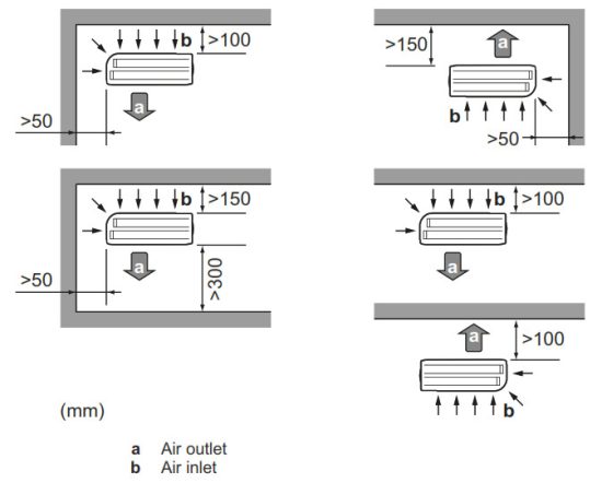
![]() NOTICE
NOTICE
The height of the wall on the outlet side of the outdoor unit MUST be ≤1200 mm.
It is recommended to install a baffle plate when the air outlet is exposed to wind. It is recommended to install the outdoor unit with the air inlet facing the wall and NOT directly exposed to the wind. Do NOT install the unit in sound sensitive areas (e.g. near a bedroom), so that the operation noise will cause no trouble.
Note: If the sound is measured under actual installation conditions, the measured value might be higher than the sound pressure level mentioned in “Sound spectrum” in the data book due to environmental noise and sound reflections.
![]() INFORMATION
INFORMATION
The sound pressure level is less than 70 dBA.
The outdoor unit is designed for outdoor installation only and for ambient temperatures specified in the table below (unless otherwise specified in the operation manual of the connected indoor unit).
| Model | Cooling | Heating |
| RXM-R, ARXM-R | –10~50°C DB | –20~24°C DB |
| RXA-A, RXJ-M | –10~46°C DB | –15~24°C DB |
Additional installation site requirements of the outdoor unit in cold climates
Protect the outdoor unit against direct snowfall and take care that the outdoor unit is NEVER snowed up.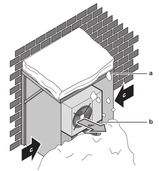
a. Snow cover or shed
b. Pedestal
c. Prevailing wind direction
d. Air outlet
It is recommended to provide at least 150 mm of free space below the unit (300 mm for heavy snowfall areas). Additionally, make sure the unit is positioned at least 100 mm above the maximum expected level of snow. If necessary, construct a pedestal. See “4.2 Mounting the outdoor unit” [4 8] for more details. In heavy snowfall areas it is very important to select an installation site where the snow will NOT affect the unit. If lateral snowfall is possible, make sure that the heat exchanger coil is NOT affected by the snow. If necessary, install a snow cover or shed and a pedestal.
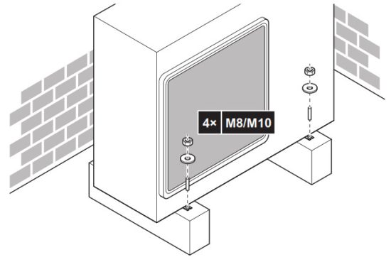
Mounting the outdoor unit
To provide the installation structure
Use a vibration-proof rubber (field supply) in cases where vibrations may be transmitted to the building.
Prepare 4 sets of M8 or M10 anchor bolts, nuts and washers (field supply).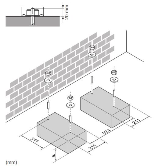 a. 100 mm above expected level of snow
To install the outdoor unit
To provide drainage
![]() NOTICE
NOTICE
If the unit is installed in a cold climate, take adequate measures so that the evacuated condensate CANNOT freeze.![]() NOTICE
NOTICE
If the drain holes of the outdoor unit are blocked up by a mounting base or floor surface, place additional foot bases ≤30 mm under the outdoor unit’s feet.![]() INFORMATION
INFORMATION
For information on the available options, contact your dealer.
- Use a drain plug for drainage.
- Use a Ø16 mm hose (field supply).
a Drain port
b Bottom frame
c Drain plug
d Hose (field supply)
Piping installation
Preparing refrigerant piping
Refrigerant piping requirements
![]() NOTICE
NOTICE
The piping and other pressure-containing parts shall be suitable for refrigerant. Use phosphoric acid deoxidised seamless copper for refrigerant.
▪ Piping material: Phosphoric acid deoxidised seamless copper.
▪ Flare connections: Only use annealed material.
▪ Piping diameter:
| Liquid piping | Ø6.4 mm (1/4″) |
| Gas piping | Ø9.5 mm (3/8″) |
▪ Piping temper grade and thickness:
| Outer diameter (Ø) | Temper grade | Thickness (t) (a) | |
| 6.4 mm (1/4″) | Annealed (O) | ≥0.8 mm | 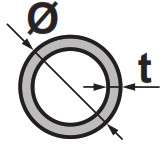 |
| 9.5 mm (3/8″) | Annealed (O) |
(a) Depending on the applicable legislation and the maximum working pressure of the unit (see “PS High” on the unit name plate), larger piping thickness might be required.
Refrigerant piping insulation
- Use polyethylene foam as insulation material:
- with a heat transfer rate between 0.041 and 0.052 W/mK (0.035 and 0.045 kcal/mh°C)
- with a heat resistance of at least 120°C
- Insulation thickness
| Pipe outer diameter (Øp) | Insulation inner diameter (Øi) | Insulation thickness (t) |
| 6.4 mm (1/4″) | 8~10 mm | ≥10 mm |
| 9.5 mm (3/8″) | 12~15 mm |
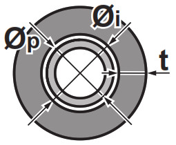
If the temperature is higher than 30°C and the humidity is higher than RH 80%, the thickness of the insulation materials should be at least 20 mm to prevent condensation on the surface of the insulation.
Refrigerant piping length and height difference
| What? | Distance |
| Maximum allowable pipe length | 20 m |
| What? | Distance |
| Minimum allowable pipe length | 1.5 m |
| Maximum allowable height difference | 15 m |
Connecting the refrigerant piping
![]() DANGER: RISK OF BURNING/SCALDING
DANGER: RISK OF BURNING/SCALDING
![]() CAUTION
CAUTION
- No brazing or welding on site for units with R32 refrigerant charge during shipment.
- During installation of the refrigeration system, joining of parts with at least one part charged shall be performed taking into account the following requirements: inside occupied spaces non-permanent joints are not allowed for R32 refrigerant except for site made joints directly connecting the indoor unit to piping. Site made joints directly connecting piping to indoor units shall be of non-permanent type.
To connect the refrigerant piping to the outdoor unit
- Piping length. Keep field piping as short as possible.
- Piping protection. Protect the field piping against physical damage.
![]() WARNING
WARNING
Connect the refrigerant piping securely before running the compressor. If the refrigerant piping is NOT connected and the stop valve is open when the compressor is run, air will be sucked in. This will cause abnormal pressure in the refrigeration cycle, which may result in equipment damage and even injury.![]() CAUTION
CAUTION
- Use the flare nut fixed to the unit.
- To prevent gas leakage, apply refrigeration oil only to the inside of the flare. Use refrigeration oil for R32.
- Do NOT reuse joints.
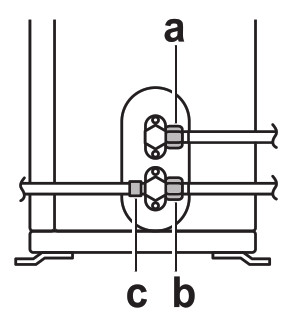
- Connect the liquid refrigerant connection from the indoor unit to the liquid stop valve of the outdoor unit.
 a Liquid stop valve
b Gas stop valve
c Service port - Connect the gas refrigerant connection from the indoor unit to the gas stop valve of the outdoor unit.
 a Liquid stop valve
![]() NOTICE
NOTICE
It is recommended that the refrigerant piping between indoor and outdoor unit is installed in a ducting or the refrigerant piping is wrapped with finishing tape.
Checking the refrigerant piping
To check for leaks
![]() NOTICE
NOTICE
Do NOT exceed the unit’s maximum working pressure (see “PS High” on the unit name plate).![]() NOTICE
NOTICE
ALWAYS use a recommended bubble test solution from your wholesaler.
NEVER use soap water:
- Soap water may cause cracking of components, such as flare nuts or stop valve caps.
- Soap water may contain salt, which absorbs moisture that will freeze when the piping gets cold.
- Soap water contains ammonia which may lead to corrosion of flared joints (between the brass flare nut and the copper flare).
- Charge the system with nitrogen gas up to a gauge pressure of at least 200 kPa (2 bar). It is recommended to pressurize to 3000 kPa (30 bar) in order to detect small leaks.
- Check for leaks by applying the bubble test solution to all connections.
- Discharge all nitrogen gas.
To perform vacuum drying
![]() DANGER: RISK OF EXPLOSION
DANGER: RISK OF EXPLOSION
Do NOT start the unit if it is vacuumed.
- Vacuum the system until the pressure on the manifold indicates −0.1 MPa (−1 bar).
- Leave as is for 4-5 minutes and check the pressure:
If the pressure… Does not change Increases - Vacuum the system for at least 2 hours to a manifold pressure of −0.1 MPa (−1 bar).
- After turning the pump OFF, check the pressure for at least 1 hour.
- If you do NOT reach the target vacuum or CANNOT maintain the vacuum for 1 hour, do the following:
▪ Check for leaks again.
▪ Perform vacuum drying again.
![]() NOTICE
NOTICE
Make sure to open the stop valves after installing the refrigerant piping and performing vacuum drying. Running the system with the stop valves closed may break the compressor.
Charging refrigerant
About the refrigerant
This product contains fluorinated greenhouse gases. Do NOT vent gases into the atmosphere.
Refrigerant type: R32
Global warming potential (GWP) value: 675
WARNING: MILDLY FLAMMABLE MATERIAL
The refrigerant inside this unit is mildly flammable.![]() WARNING
WARNING
The appliance shall be stored in a room without continuously operating ignition sources (example: open flames, an operating gas appliance or an operating electric heater).![]() WARNING
WARNING
▪ Do NOT pierce or burn refrigerant cycle parts.
▪ Do NOT use cleaning materials or means to accelerate the defrosting process other than those recommended by the manufacturer.
▪ Be aware that the refrigerant inside the system is odourless.![]() WARNING
WARNING
The refrigerant inside the unit is mildly flammable, but normally does NOT leak. If the refrigerant leaks in the room and comes in contact with fire from a burner, a heater, or a cooker, this may result in fire, or the formation of a harmful gas.
Turn off any combustible heating devices, ventilate the room, and contact the dealer where you purchased the unit.
Do NOT use the unit until a service person confirms that the part from which the refrigerant leaked has been repaired.![]() WARNING
WARNING
NEVER directly touch any accidental leaking refrigerant.
This could result in severe wounds caused by frostbite.
To determine the additional refrigerant amount
| If the total liquid piping length is… | Then… |
| ≤10 m | Do NOT add additional refrigerant. |
| >10 m | R=(total length (m) of liquid piping–10 m)×0.020 R=Additional charge (kg) (rounded in units of 0.01 kg) |
![]() INFORMATION
INFORMATION
Piping length is the one-way length of liquid piping.
To determine the complete recharge amount
![]() INFORMATION
INFORMATION
If a complete recharge is necessary, the total refrigerant charge is: the factory refrigerant charge (see unit name plate) + the determined additional amount.
To charge additional refrigerant
![]() WARNING
WARNING
- Only use R32 as refrigerant. Other substances may cause explosions and accidents.
- R32 contains fluorinated greenhouse gases. Its global warming potential (GWP) value is 675. Do NOT vent these gases into the atmosphere.
- When charging refrigerant, ALWAYS use protective gloves and safety glasses.
Prerequisite:
Before charging refrigerant, make sure the refrigerant piping is connected and checked (leak test and vacuum drying).
- Connect the refrigerant cylinder to the service port.
- Charge the additional refrigerant amount.
- Open the gas stop valve.
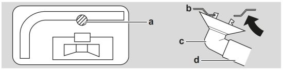
To fix the fluorinated greenhouse gases label
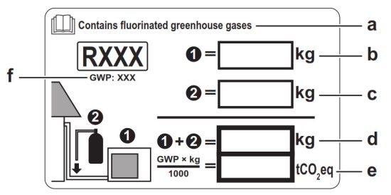
- Fill in the label as follows:
 a. If a multilingual fluorinated greenhouse gases label is delivered with the unit (see accessories), peel off the applicable language and stick it on top of a.
b. Factory refrigerant charge: see unit name plate
c. Additional refrigerant amount charged
d. Total refrigerant charge
e. Quantity of fluorinated greenhouse gases of the total refrigerant charge expressed as tonnes CO2 equivalent.
f. GWP = Global warming potential
 a. If a multilingual fluorinated greenhouse gases label is delivered with the unit (see accessories), peel off the applicable language and stick it on top of a.
![]() NOTICE
NOTICE
Applicable legislation on fluorinated greenhouse gases requires that the refrigerant charge of the unit is indicated both in weight and CO2 equivalent.
Formula to calculate the quantity in CO2 equivalent tonnes: GWP value of the refrigerant × total refrigerant charge [in kg] / 1000
Use the GWP value mentioned on the refrigerant charge label.
2 Fix the label on the inside of the outdoor unit near the gas and liquid stop valves.
Electrical installation
![]() DANGER: RISK OF ELECTROCUTION
DANGER: RISK OF ELECTROCUTION![]() WARNING
WARNING
- All wiring MUST be performed by an authorised electrician and MUST comply with the applicable legislation.
- Make electrical connections to the fixed wiring.
- All components procured on-site and all electrical construction MUST comply with the applicable legislation.
![]() WARNING
WARNING
ALWAYS use multicore cable for power supply cables.![]() WARNING
WARNING
Use an all-pole disconnection type breaker with at least 3 mm between the contact point gaps that provide full disconnection under overvoltage category III.![]() WARNING
WARNING
If the supply cord is damaged, it MUST be replaced by the manufacturer, its service agent or similarly qualified persons in order to avoid a hazard.![]() WARNING
WARNING
Do NOT connect the power supply to the indoor unit. This could result in electrical shock or fire.![]() WARNING
WARNING
- Do NOT use locally purchased electrical parts inside the product.
- Do NOT branch the power supply for the drain pump, etc. from the terminal block. This could result in electrical shock or fire.
![]() WARNING
WARNING
Keep the interconnection wiring away from copper pipes without thermal insulation as such pipes will be very hot.![]() DANGER: RISK OF ELECTROCUTION
DANGER: RISK OF ELECTROCUTION
All electrical parts (including thermistors) are powered by the power supply. Do not touch them with bare hands.![]() DANGER: RISK OF ELECTROCUTION
DANGER: RISK OF ELECTROCUTION
Disconnect the power supply for more than 10 minutes, and measure the voltage at the terminals of main circuit capacitors or electrical components before servicing. The voltage MUST be less than 50 V DC before you can touch electrical components. For the location of the terminals, see the wiring diagram.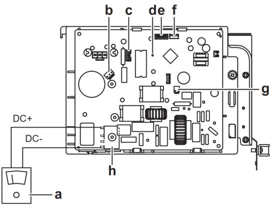
a Multimeter (DC voltage range)
b S80 – reversing solenoid valve lead wire
c S70 – fan motor lead wire
d LED
e S90 – thermistor lead wire
f S20 – electronic expansion valve lead wire
g S40 – thermal overload relay lead wire
h DB1 – diode bridge
Specifications of standard wiring components
| Component | Class 20 | Class 25+35 | |
| Power supply cable | Voltage | 220-240 V | |
| Phase | 1- | ||
| Frequency | 50 Hz | ||
| Wire sizes | 3-core cable 2.5 mm2-4.0 mm2 HO5RN-F (60245 IEC 57) | ||
| Interconnection cable (indooroutdoor) | 4-core cable 1.5 mm2-2.5 mm2 and | ||
| Recommended circuit breaker | 10 A | 13 A | |
| Residual current device | MUST comply with applicable legislation | ||
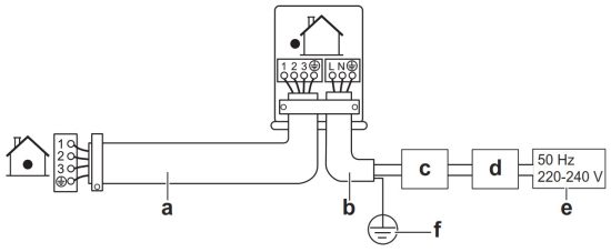
To connect the electrical wiring to the outdoor unit
- Remove the service cover.
- Open the wire clamp.
- Connect the interconnection cable and power supply as follows:
 a. Interconnection cable
b. Power supply cable
c. Circuit breaker
d. Residual current device
e. Power supply
f. Earth
- Tighten the terminal screws securely. We recommend using a Phillips screwdriver.
- Install the service cover.
 a. Interconnection cable
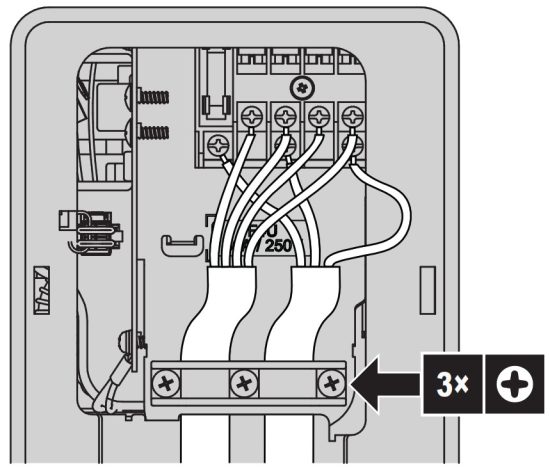
Finishing the outdoor unit installation
To finish the outdoor unit installation
![]() DANGER: RISK OF ELECTROCUTION
DANGER: RISK OF ELECTROCUTION
- Make sure that the system is earthed properly.
- Turn off the power supply before servicing.
- Install the switch box cover before turning on the power supply.
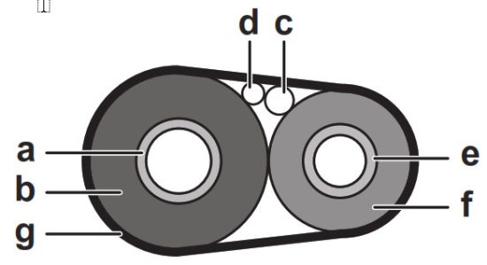
- Insulate and fix the refrigerant piping and cables as follows:
 a. Gas pipe
b. Gas pipe insulation
c. Interconnection cable
d. Field wiring (if applicable)
e. Liquid pipe
f. Liquid pipe insulation
g. Finishing tape - Install the service cover.
 a. Gas pipe
Configuration
Facility setting
Use this function for cooling at low outdoor temperature. This function is designed for facilities such as equipment of computer rooms. NEVER use in a residence or office where people occupy the space.
Applicable for: RXM-R, ARXM-R, RXJ-M, RXA-A.
To set the facility mode
When cutting jumper J6 on the PCB, the operation range will expand to –15°C. The facility mode will stop if the outdoor temperature drops below –20°C and resume when the temperature rises again.
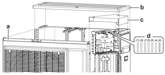
To cut jumper J6
- Remove the top plate of the outdoor unit.
- Remove the front plate.
- Remove the drip proof cover.
- Cut jumper J6 on the outdoor unit PCB.
 a. Front plate
b. Top plate
c. Drip proof cover
d. Jumpers
 a. Front plate
![]() INFORMATION
INFORMATION
- The indoor unit may produce Intermittent noise due to the outdoor unit fan turning ON and/or OFF.
- Do NOT place humidifiers or other items which might raise humidity in rooms when you use the facility mode.
- Cutting jumper J6 sets the indoor unit fan to the highest speed.
- Do NOT use this setting in residences or offices with people.
Standby electricity saving function
About the standby electricity saving function
This mode turns OFF the power supply of the outdoor unit and sets the indoor unit into the standby saving mode to reduce the power consumption of the unit.
This mode is only applicable for outdoor units: ARXM25+35R, RXM20~35R and indoor units: FTXM, ATXM, FVXM.![]() INFORMATION
INFORMATION
The standby electricity saving can ONLY be used for the units described above.![]() WARNING
WARNING
Before connecting or disconnecting the connector, make sure the power supply is turned off.![]() INFORMATION
INFORMATION
Selective connector for standby electricity saving is required if other than applicable indoor unit is connected.
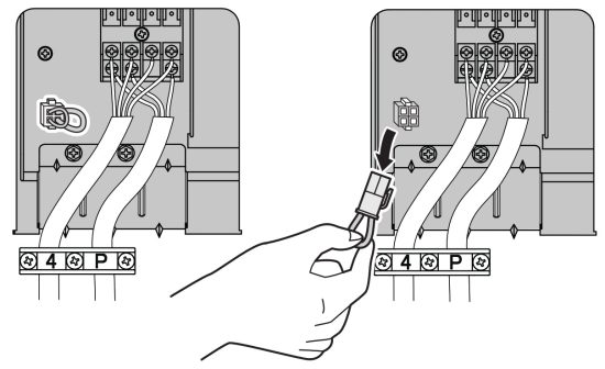
To turn on standby electricity saving function
Prerequisite: The main power supply MUST be turned off.
- Remove the service cover.
- Disconnect the selective standby electricity saving connector.

- Turn on the main power supply.
Commissioning
![]() NOTICE
NOTICE
General commissioning checklist. Next to the commissioning instructions in this chapter, a general commissioning checklist is also available on the Daikin Business Portal (authentication required).
The general commissioning checklist is complementary to the instructions in this chapter and can be used as a guideline and reporting template during the commissioning and hand-over to the user.![]() NOTICE
NOTICE
ALWAYS operate the unit with thermistors and/or pressure sensors/switches. If NOT, burning of the compressor might be the result.
Checklist before commissioning
After the installation of the unit, first check the items listed below. Once all checks are fulfilled, the unit must be closed. Power-up the unit after it is closed.
| The indoor unit is properly mounted. | |
| The outdoor unit is properly mounted. | |
| The system is properly earthed and the earth terminals are tightened. | |
| The power supply voltage matches the voltage on the identification label of the unit. | |
| There are NO loose connections or damaged electrical components in the switch box. | |
| There are NO damaged components or squeezed pipes on the inside of the indoor and outdoor units. | |
| There are NO refrigerant leaks. | |
| The refrigerant pipes (gas and liquid) are thermally insulated. | |
| The correct pipe size is installed and the pipes are | |
| properly insulated. | |
| The stop valves (gas and liquid) on the outdoor unit are fully open. | |
| The following field wiring has been carried out according to this document and the applicable legislation between the outdoor unit and the indoor unit. | |
| Drainage Make sure drainage flows smoothly. Possible consequence: Condensate water might drip. | |
| The indoor unit receives the signals of the user interface. | |
| The specified wires are used for the interconnection cable. | |
| The fuses, circuit breakers, or locally installed protection devices are installed according to this document, and have NOT been bypassed. |
Checklist during commissioning
| To perform an air purge. | |
| To perform a test run. |
To perform a test run
Prerequisite: Power supply MUST be in the specified range.
Prerequisite: Test run may be performed in cooling or heating mode.
Prerequisite: Test run should be performed in accordance with the operation manual of the indoor unit to make sure that all functions and parts are working properly.
- In cooling mode, select the lowest programmable temperature.
In heating mode, select the highest programmable temperature.
Test run can be disabled if necessary. - When the test run is finished, set the temperature to a normal level. In cooling mode: 26~28°C, in heating mode: 20~24°C.
- The system stops operating 3 minutes after the unit is turned OFF.
![]() INFORMATION
INFORMATION
- Even if the unit is turned OFF, it consumes electricity.
- When the power turns back on after a power break, the previously selected mode will be resumed.
Troubleshooting
Fault diagnosis using LED on outdoor unit PCB
| LED is… | Diagnosis | |
| flashing | Normal. ▪ Check the indoor unit. | |
| ON | ▪ Turn the power OFF and back ON, and check the LED within approximately 3 minutes. If the LED is ON again, the outdoor unit PCB is faulty. | |
| OFF | 1. Supply voltage (for power saving). 2. Power supply fault. 3. Turn the power OFF and back ON, and check the LED within approximately 3 minutes. If the LED is OFF again, the outdoor unit PCB is faulty. | |
![]() DANGER: RISK OF ELECTROCUTION
DANGER: RISK OF ELECTROCUTION
- When the unit is not operating, the LEDs on the PCB are turned off in order to save power.
- Even when the LEDs are off, the terminal block and the PCB may be powered.
Disposal
![]() NOTICE
NOTICE
Do NOT try to dismantle the system yourself: dismantling of the system, treatment of the refrigerant, oil and other parts MUST comply with applicable legislation. Units MUST be treated at a specialised treatment facility for reuse, recycling and recovery.
Technical data
- A subset of the latest technical data is available on the regional Daikin website (publicly accessible).
- The full set of latest technical data is available on the Daikin Business Portal (authentication required).
Wiring diagram
The wiring diagram is delivered with the unit, located inside of the outdoor unit (bottom side of the top plate).
Unified wiring diagram legend
For applied parts and numbering, refer to the wiring diagram on the unit. Part numbering is by Arabic numbers in ascending order for each part and is represented in the overview below by “*” in the part code.
| Symbol | Meaning | Symbol | Meaning |
| Circuit breaker |  | Protective earth | |
| Connection |  | Protective earth (screw) | |
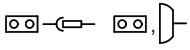 | Connector |  | Rectifier |
 | Earth | Relay connector | |
| Field wiring |  | Short-circuit connector | |
| Fuse | Terminal | ||
 | Indoor unit | Terminal strip | |
 | Outdoor unit | Wire clamp | |
| Residual current device |
| Symbol | Colour | Symbol | Colour |
| BLK | Black | ORG | Orange |
| BLU | Blue | PNK | Pink |
| BRN | Brown | PRP, PPL | Purple |
| GRN | Green | RED | Red |
| GRY | Grey | WHT | White |
| YLW | Yellow |
| Symbol | Meaning |
| A*P | Printed circuit board |
| BS* | Pushbutton ON/OFF, operation switch |
| BZ, H*O | Buzzer |
| C* | Capacitor |
| AC*, CN*, E*, HA*, HE*, HL*, HN*, HR*, MR*_A, MR*_B, S*, U, V, W, X*A, K*R_*, NE | Connection, connector |
| D*, V*D | Diode |
| DB* | Diode bridge |
| DS* | DIP switch |
| E*H | Heater |
| FU*, F*U, (for characteristics, refer to PCB inside your unit) | Fuse |
| FG* | Connector (frame ground) |
| H* | Harness |
| Symbol | Meaning |
| H*P, LED*, V*L | Pilot lamp, light emitting diode |
| HAP | Light emitting diode (service monitor green) |
| HIGH VOLTAGE | High voltage |
| IES | Intelligent eye sensor |
| IPM* | Intelligent power module |
| K*R, KCR, KFR, KHuR, K*M | Magnetic relay |
| L | Live |
| L* | Coil |
| L*R | Reactor |
| M* | Stepper motor |
| M*C | Compressor motor |
| M*F | Fan motor |
| M*P | Drain pump motor |
| M*S | Swing motor |
| MR*, MRCW*, MRM*, MRN* | Magnetic relay |
| N | Neutral |
| n=*, N=* | Number of passes through ferrite core |
| PAM | Pulse-amplitude modulation |
| PCB* | Printed circuit board |
| PM* | Power module |
| PS | Switching power supply |
| PTC* | PTC thermistor |
| Q* | Insulated gate bipolar transistor (IGBT) |
| Q*C | Circuit breaker |
| Q*DI, KLM | Earth leak circuit breaker |
| Q*L | Overload protector |
| Q*M | Thermo switch |
| Q*R | Residual current device |
| R* | Resistor |
| R*T | Thermistor |
| RC | Receiver |
| S*C | Limit switch |
| S*L | Float switch |
| S*NG | Refrigerant leak detector |
| S*NPH | Pressure sensor (high) |
| S*NPL | Pressure sensor (low) |
| S*PH, HPS* | Pressure switch (high) |
| S*PL | Pressure switch (low) |
| S*T | Thermostat |
| S*RH | Humidity sensor |
| S*W, SW* | Operation switch |
| SA*, F1S | Surge arrester |
| SR*, WLU | Signal receiver |
| SS* | Selector switch |
| SHEET METAL | Terminal strip fixed plate |
| T*R | Transformer |
| TC, TRC | Transmitter |
| V*, R*V | Varistor |
| V*R | Diode bridge, Insulated-gate bipolar transistor (IGBT) power module |
| WRC | Wireless remote controller |
 3P650253-1
![]()
DAIKIN ISITMA VE SOĞUTMA SİSTEMLERİ SAN.TİC. A.Ş.
Gülsuyu Mahallesi, Fevzi Çakmak Caddesi, Burçak Sokak, No:20, 34848 Maltepe
İSTANBUL / TÜRKİYE
Tel: 0216 453 27 00
Faks: 0216 671 06 00
Çağrı Merkezi: 444 999 0
Web: www.daikin.com.tr


