DRIVEN DRA1001.1 DRA Series Amplifiers
INTRODUCTION
Congratulations on your purchase of this DRIVEN Audio Amplifier. Your selection of a DRIVEN product indicates a true appreciation of fine musical reproduction. To ensure proper use of this unit, please make sure to read the owner’s manual carefully before operating and keep it for future reference.
KEEP YOUR SALES RECEIPT
Take this time to attach your sales receipt to the manual and out in a safe place. In case of any unforseen reason this product may need warranty service, your receipt will be necessary to establish purchase date.
RECOMMENDATION
An amplifiers perfomance is only as good as its installation. Proper installation will maximize the system’s overall performance. It is recommended that you have our product installed by an authorized DRIVEN retailer. If you decide to install it yourself, please carefully read through this manual and take your time to do a quality installtion.
Due to continuing product improvements and possible manual revisions, we recommend checking our website for the latest product information at: www.drivenelectronics.com
IMPORTANT! Before making any connections, disconnect the vehicle’s battery until the installation is completed to avoid possible damage to the electrical system.
WARNING!
Exposure to high power sound system can cause hearing loss or damage. Listening to your system at loud levels while driving will impair your ability to hear traffic sounds and emergency vehicles.
Use common sense when listening to your system.
SAFETY PRECAUTIONS
Fuse amplifiers power wire at the battery
Be sure to fuse the power wire within 12″ of the car’s battery. This will protect the car’s battery in case of a short circuit between the power amplifier and battery. THIS IS A MUST, the amplifier’s built-in fuse will only protect the power amplifier not the car’s battery!
Use high grade wire connectors
To ensure maximum power transfer and secure safe connections, it is recommended to use high grade barrier spades (for connection at amplifier) and terminal rings (for connection at battery).
Do not run any wires underneath vehicle
Exposed wires have a chance of being cut or damaged. It is best to run all wires through the vehicle under the carpet and/or side panels. This lends to a cleaner installation and less risk of damage.
Use caution when mounting amplifier
Remember there are many electrical wires, gas lines, vacuum lines, brake lines as well as a gas tank in the automobile. Make sure you now where they are when mounting the amplifier to avoid puncturing lines, shorting wires or drilling holes in the gas tank.
Run signal wires away from electrical wires
To avoid possibility of induced noise from the ca(s electrical system (i.e. popping noises or engine noise), run wires away from the car’s electrical wiring.
Make all ground wires as short as possible and at the same point.
In order to reduce the chance of ground loops (i.e. engine noise), make the grounding wire as short as possible to reduce the wire’s resistance. Also, when using multiple components, make sure all units are grounded at the same point.
Avoid sharp edges when running the wires
To avoid the possibility of power, signal or speaker shorts, be careful not to allow the amplifiers wires to come in contact with sharp edges. Use a grommet to protect the wire when running through the fire wall.
FEATURES AND BENEFITS
DC Offset Protection
This circuit protects the output of the amplifier against DC voltage. If for some reason DC voltage is detected at the output stage, the amplifier will shut down protecting the speakers from direct current.
Short Circuit Protection
The circuit protects the amplifier from damage due to a short found in the speakers or wiring. If one of the speakers or its wiring comes in contact with ground, the amplifier will shut down. To resume normal operation, correct the problem and turn the head unit off, then back on. The amplifier will reset and play again.
Thermal Protection
To protect the amplifier circuitry against damage caused by prolonged exposure to high temperatures, a thermal protection circuit is activated if the amplifier reaches excessively high operating temperature. Once the thermal circuit is activated, the amplifier will shut down to cool off. The amplifier will automatically turn back on once it cools down to a safe operating temperature.
Power Indicator
The diagnostic L.E.D. illuminates when the amplifier is on and receiving power.
Built-in Crossover
The DRIVEN DRAB, DRA4 and DRA2 are equiped with a built in variable crossover network allowing you to select the crossover function and frequency for each the front channels or rear channels of the amplifier independently.
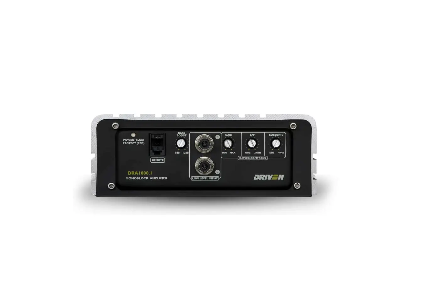
The DRIVEN DRA3000.1, DRA2000.1 and DRA1000.1 Monoblock Amplifiers are equipped with a built in variable lowpass crossover network allowing you to select the crossover function and frequency for each the front channels or rear channels of the amplifier independently.
Power and Speaker Distribution Blocks
Heavy gauge bare wire distribution blocks are provided for maximum power and signal transfer with minimal resistance.
LOW IMPEDANCE STABILITY
Full range line outputs have been provided for convenient connection to additional amplifiers in the system. The outputs are buffered to reduce signal loss.
POWER FUSING
This protects the amplifier against short circuits and excessive current.
REMOTE TURN- ON
Automatically turns amplifier on when connected to the head unit’s remote output. amplifier will turn on and off with the head unit to save current consumption. This control also operates the reset circuit for the amplifier’s protection. It must be connected withthe head unit in order to reset protection circuits.
ADJUSTABLE INPUT SENSITIVITY
Allows you to fine-tune the level matching between your source and the power amplifier.
LOW IMPEDANCE STABILITY
4 CHANNEL STEREO AMPLIFIERS | HEIGHT | WIDTH | LENGTH |
DRA4 20 STEREO | 2″ I 55 mm | 6″/153mm | 11.2″ / 285 mm |
| DRAB 20 STEREO | 2″ I 55 mm | 6″/153mm | 6.9″ I 345 mm |
2 CHANNEL STEREO AMPLIFIER | |||
DRA2 20 STEREO | 2″ I 55 mm | 6″/153mm | 6.9″ I 175 mm |
MONOBLOCK AMPLIFIERS | |||
DRA3000.1 10 MONO | 2″ I 55 mm | 6″/153mm | 13″ / 333 mm |
DRA2000.1 10 MONO | 2″ I 55 mm | 6″/153mm | 10″ / 253 mm |
| DRA1000.1 20 MONO | 2″ I 55 mm | 6″/153mm | 6.89″ I 175 mm |
BUILT-IN CROSSOVER
DRA4,DRA8
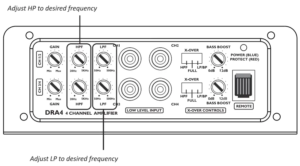
The DRA4 and DRAB amplifier allow you to select the crossovermode (High-Passfull Range or Low Pass/ Band Pass)and desired crossover point for channels 1-2 and 3-4.
For example if you wish to use a 2-way loud speaker on channels 1-2, simply set the crossover switch to HPF and adjust the frequency setting to the desired HPF setting to block out any unwated low frequencies.
block out any unwated low frequencies.
If you wish to run a subwoofer on channels3-4,simplysetthe crossoverswitchto LP/BP.
You must adjust the HPF Frequency setting to 50 Hz and the LPF Frequency setting to the desired Low Pass setting to block out unwanted high frequencies.
If you wish to run a component midrange on either channels 1-2or 3-4setthe crossover switch to LP/BP.Then use both HPFand LPFfrequency controls to create the desired band pass frequency range.
THESE SETTING CAN BE USE ON CHANNELS 1-2 OR 3-4
INDEPENDENTLY OR FOR ALL CHANNELS
4 CHANNEL STEREO AMPLIFIERS
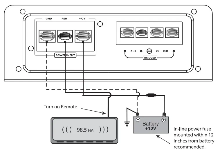
Power Connection Leads
Notes on the Power Supply
the ground wire of the unit securely to a metal part of the car. A lose connection may cause a malfunction of the amplifier.
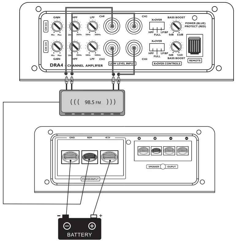
REMOTE:The unit is turned on by applying+ 12Volts to this terminal. This terminal does not draw heavy current like the two power terminal so a thinner connecting wire is acceptable. Standard 18 GUAGE is fine and the standard color is yellow. If the power antenna wire is already in use, you can still splice into it. With this method, the unit will turn on automatically with the radio. Use the power supply lead with a fuse attached whose value is the same as original fuse.
Place the fuse in the power supply lead as close as possible to the car battery.
During a full power operation. Maximum current will run through the system. Therefore,Make sure that the leads to be connected to the+ 12Vand GND terminals of the unit respectively must be larger than 10-Guage(AWGl0).
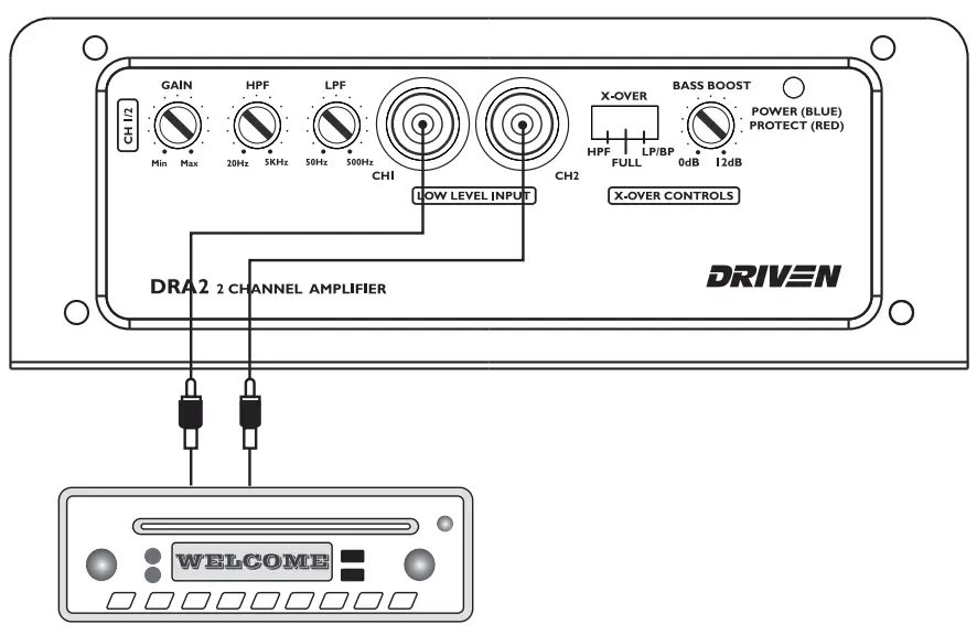
2 CHANNEL
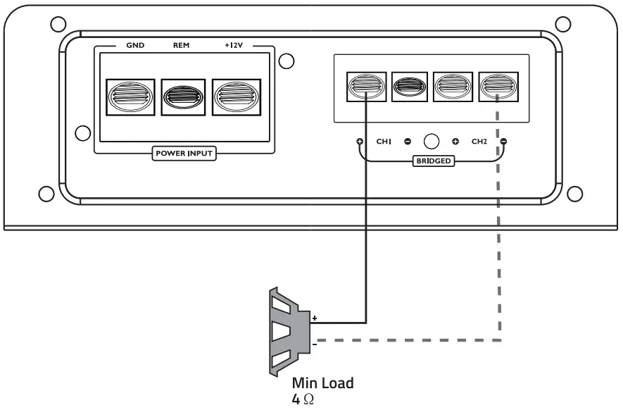
Bridged
Stereo
4 CHANNEL
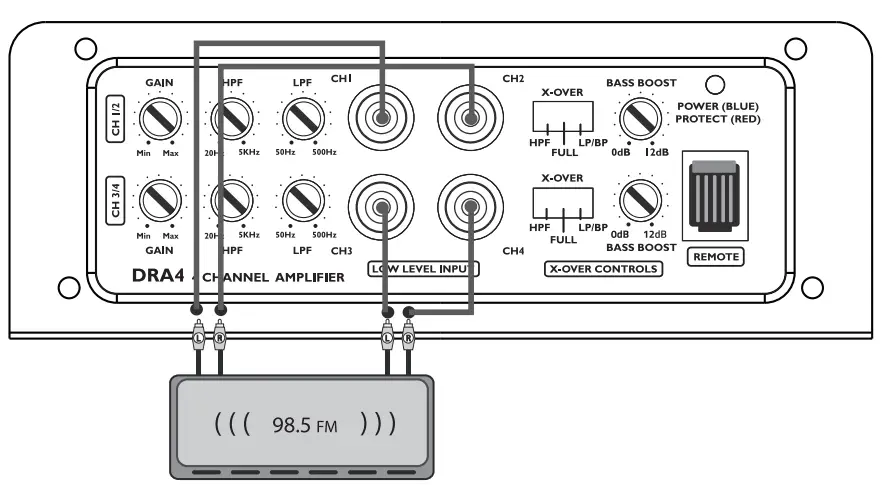
System 1: 4 Channel Model
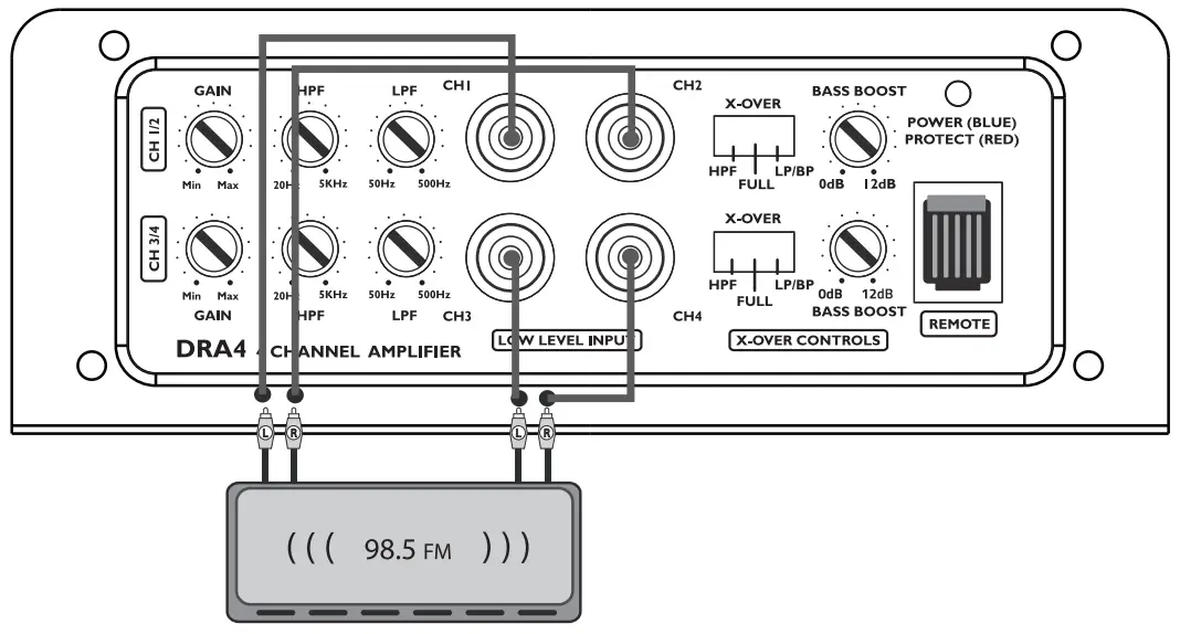

4 CHANNEL AMPLIFIER
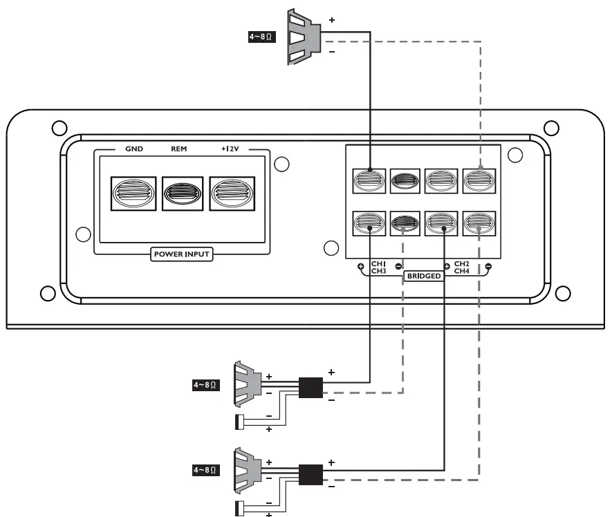
System 2: Bridged / Stereo Connection Subwoofer
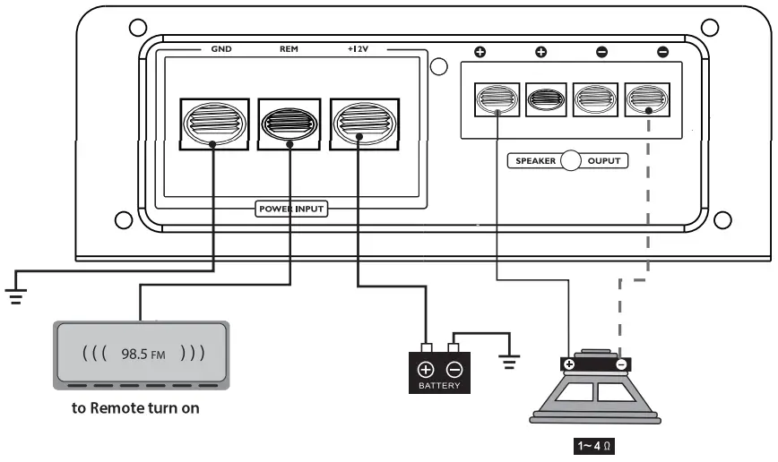
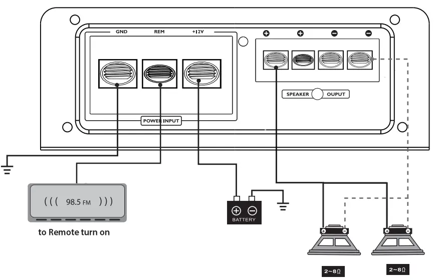
Subwoofer Connection
MONOBLOCK AMPLIFIERS
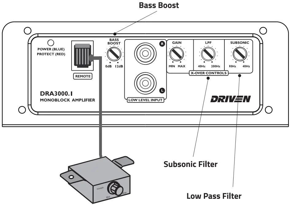
Built – In – Crossover
DRA30001 .1 / DRA2000.1 / DRA 1000.1
The DRIVEN Mono Amplifiers are equipped with a 24dB per octave variable Low Pass crossover.
They also feature a variable Sub Sonic filter between 1 0Hz – 40Hz to protect your’ subwoofers from ultra low frequencies when using vented enclosures.
A Variable Bass Boost is available to tune your subwoofer enclosure.
EXTERNEL FUSE RATINGS
DRA3OOO.1 – 2OOA
DRA2OOO.1 -15OA
DRA1OOO.1 – BOA
DRAB-BOA
DRA4-4OA
DRA2-3OAx 2
Power Connections
IMPORTANT! Before making any connections, disconnect the car’s battery until the installation is completed to avoid possible damage to the electrical system.
- It is important that you read this manual very carefully and follow it for your installation carefully. Before you start your installation,please consider following concerns. Check the battery and alternator ground(-) connections. Make sure they are properly connected and free of corrosion.
- Before selecting a mounting location for amplifier, please take some concerns into consideration with cooling efficiency and safety.
- Power connection
Before installing amplifier,disconnect the negative(-) wire from battery to protect any accidental damage to your amplifier and System.This Amplifier is designed to use 4 AWG POWER and GROUND cables. - Ground connection
Locate a secure grounding connection as close to the amplifier as possible. Make sure the location is clean and provides a direct electrical connection to the frame of the vehicle.Connect one end of a short piece of the same size cables as the power cable to the grounding point.Run the other end of the cable to the amplifier mounting location. Connecting the ground cable to the screw terminal labeled as GND. - Remote connection
Run a remote turn on cable from the switched+ 12V source you will be using to turn on the system components. This may be a toggle switch, a relay, or your source unit’s remote trigger wire, or power antenna trigger wire. Connect the remote turn on cable to the power terminal labeled as REM. Run this lead to the amplifier mounting location. Using 16AWG wire or larger.
RCA CONNECTIONS MONOBLOCK
SINGLE AMP INPUT CONNECTION
SPEAKERS CONNECTIONS
4 CHANNEL & 2 CHANNEL
DRA4 I DRAB I DRA2
Features:
- Class A/B Circuitry
- 212 Load Stereo Capability
- Low level RCA inputs
- Selectable HP/LP *2 Channel / Selectable HP/LP/BP *4 Channel
- High Efficiency Mosfet Design
- Heat Management System
- Bridgeable outputs @4!2 load
Specifications:
| DRA4 | DRAB | |
| Rated Power: Rated Power: Rated Power: | 4x 150Watts@40Stereo 4 x 375 Watts@2 n Stereo 2 x 750 Watts@4 0 Bridged Compatibility 2 n Stereo | 4x 150Watts@40Stereo 4 x 375 Watts@2 n Stereo 2 x 750 Watts@4 0 Bridged Compatibility 2 n Stereo |
| TH D at Rated Power: Bandwidth: Damping Factor: Signal to Noise Ratio: Input Sensitivity: Minimum Load Impedance: Input Crossover Filter Slope in Stereo: Channel 1-2 HP Filter Range: Channel 3-4 LP / BP Filter Range: Selectable Bass Boost: | >0.5% (-3 dB)- 18Hz- 22Hz ( 1kHz@4n)-100 >90dB 285Mv-6V 2nStereo Pre in RCA 12dB 20Hz-SKHz S0Hz-S00Hz @45Hz – 0-12dB | >0.5% (-3 dB)- 18Hz- 22Hz ( 1kHz@4n)-100 >90dB 285Mv-6V 2nStereo Pre in RCA 12dB 20Hz-SKHz S0Hz-S00Hz @45Hz – 0-12dB |
Specifications:
| DRA2 | |
| Rated Power: Rated Power: Rated Power: | 2×150 Watts(.@ 4 0 Stereo 2 x 375 Watts(.@ 2 0 Stereo 1 x 750 Watts (.@ 4 0 Bridged Compatibility 2 0 Stereo |
| THD at Rated Power: | >0.5% |
| Bandwidth: | (-3 dB) – 18Hz- 22KHz |
| Damping Factor: | ( lk Hz (.@ 40) -100 |
| Signal to Noise Ratio: | >90dB |
| Input Sensitivity: | 285Mv-6V |
| Minimum Load Impedance | 2OStereo |
| Input: | Pre in RCA |
| Crossover Filter Slope in Stereo: | 12dB |
| HP Filter Range: | 20Hz- 5KHz |
| LP Filter Range: | 50Hz-500Hz |
| Selectable Bass Boost | (.@45Hz – 0-12dB |
MONOBLOCK AMPLIFIERS
DRA3000.1
Monoblock Amplifier
Features:
- Class D Monoblock circuitry
- 1 n Load Mono Capability
- Low level RCA inputs
- Variable Low Pass Crossover
- Variable Sub-sonic Filter
- High Efficiency Mosfet Design
- Heat Management System
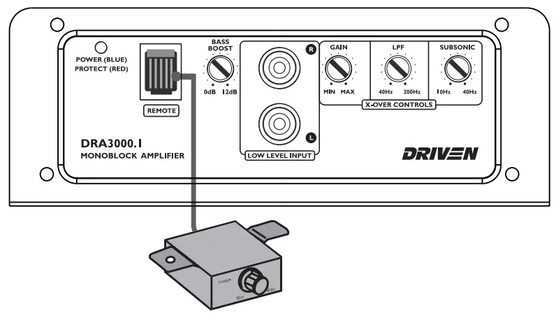
- Remote Dash Bass Control
DRA2000.1
Monoblock Amplifier
Features:
- Class D Monoblock circuitry
- 1 n Load Mono Capability
- Low level RCA inputs
- Variable Low Pass Crossover
- Variable Sub-sonic Filter
- High Efficiency Mosfet Design
- Heat Management System
- Remote Dash Bass Control
DRA1000.1
Monoblock Am lifier
Features:
- Class D Monoblock circuitry
- 1 n Load Mono Capability
- Low level RCA inputs
- Variable Low Pass Crossover
- Variable Sub-sonic Filter
- High Efficiency Mosfet Design
- Heat Management System
- Remote Dash Bass Control
Specifications:
| DRA3000.1 | DRA2000.1 | DRA1000.1 | |
| Monoblock | Monoblock | Monoblock | |
| Rated Power: Rated Power: Rated Power: | 1 x 3000W (@ 10 Mono 1 x 1500W (@ 20 Mono 1 x 750W (@ 40 Mono | 1 x 3000W (@ 10 Mono 1 x 1500W (@ 20 Mono 1 x 750W (@ 40 Mono | 1 x 3000W (@ 10 Mono 1 x 1500W (@ 20 Mono 1 x 750W (@ 40 Mono |
| TH D at Rated Power: Bandwidth: Damping Factor: Signal to Noise Ratio: Input Sensitivity: Minimum Load Impedance: Phase Shift Selector: Mono Low Pass Filter Slope: Low Pass filter range: Sub – Sonic Filter slope: Sub- Sonic Filter Range: Selectable Bass Boost (@45 Hz: | >0.5% (-3 dB) -18Hz- 200Hz (1kHz(@ 4ol-126 >90dB 285Mv -6V lo Mono 0-180* 12dB 40Hz-200Hz 12dB 10 Hz-40 Hz 0-12dB | >0.5% (-3 dB) -18Hz- 200Hz (1kHz(@ 4ol-126 >90dB 285Mv -6V lo Mono 0-180* 12dB 40Hz-200Hz 12dB 10 Hz-40 Hz 0-12dB | >0.5% (-3 dB) -18Hz- 200Hz (1kHz(@ 4ol-126 >90dB 285Mv -6V lo Mono 0-180* 12dB 40Hz-200Hz 12dB 10 Hz-40 Hz 0-12dB |