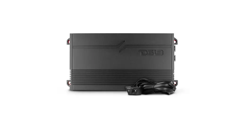
![]() G1800.1D Class D Car Audio Amplifiers
G1800.1D Class D Car Audio Amplifiers
Owner’s Manual
INTRODUCTION
Thank you for choosing the DS18 GEN-X series amp! Your choice indicates a desire for high-quality music reproduction in the automobile. DS18 amps bring to you decades of car audio expertise. So whether you are a daily driving music lover or a serious car audio competitor. DS18 has the product for you!
To take full advantage of the new gear you have just purchased, please read and follow the instructions in this manual. As with all of our products, professional installation by an authorized DS18 dealer is highly recommended. Otherwise, the performance of your new gear may not be satisfactory. In the event that you decide to do your own installation, please read and follow this manual very carefully. Failure to do so many compromises the integrity of this product, your automobile, and possibly void the product warranty.
FEATURES
- Compact size for easy installation.
- Variable Full Crossover Filters: LPF / FULL /HPF (G1800.4D, G3600.4D, G8400.4D).
- Remote level knob control with Clip /Power / Protection LED Indicator (G1800.1D, G3600.1D).
- Hi-level input compatibility (G1800.1D, G3600.1D).
- Surface mount component technology.
- Audio precision quality control verification.
- Stable & reliable Digital circuit design.
- Power, protection and clipping LED Lights status indicator.
- Short circuit thermal, DC offset, and High and Low voltage protection.
CONTROLS AND ADJUSTMENTS
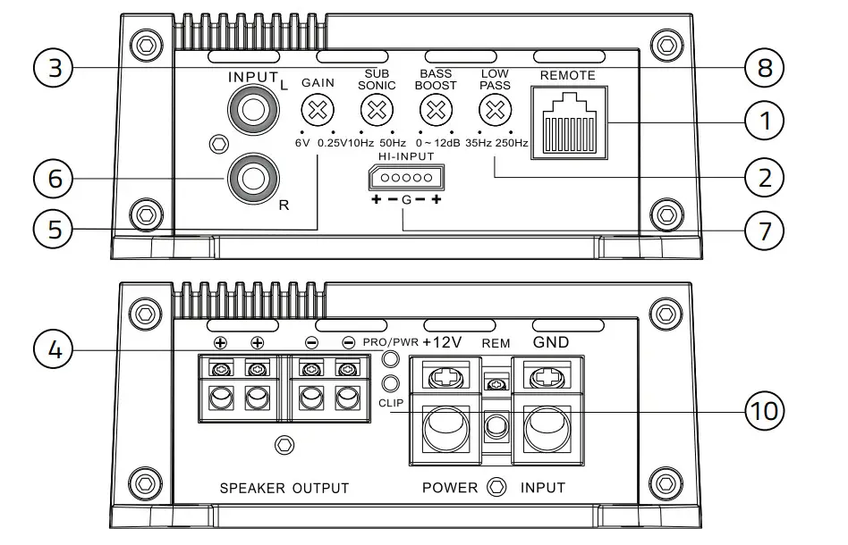
G1800.1D/G3600.1D
G1800.4D/G3600.4D/G8400.4D
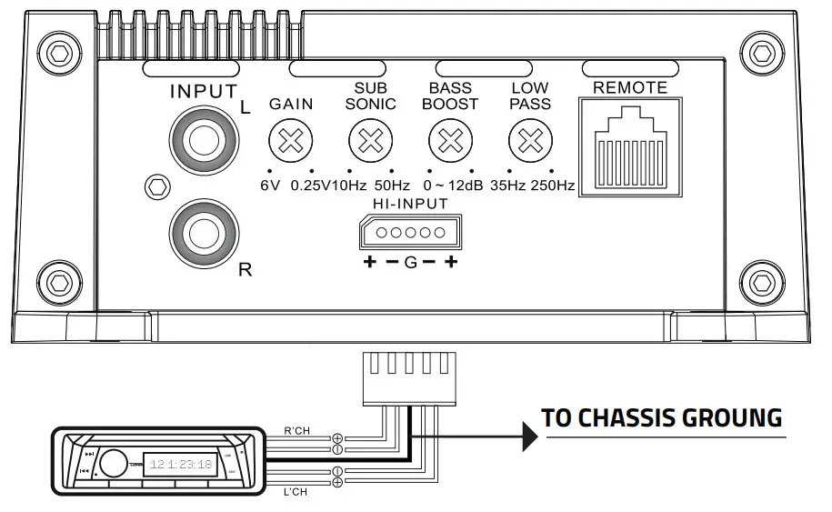
- Remote Level Control Connection Connect the remote level control to this terminal. The remote level control allows adjustment of the subwoofer level from a remote location in the vehicle.
- Low Pass Crossover
Adjust the frequency setting of the low pass crossover. Frequencies higher than the setting will be filtered out of the audio signal. - Subsonic Crossover
Adjust the frequency setting of the subsonic crossover. The frequency range is 10Hz-50 Hz.
Frequencies lower than the setting will be filtered out of the audio signal. - Power Protection indicator Led When the amplifier is on and in proper working condition, the green LED will illuminate. Refer to the Troubleshooting Guide for possible solutions if the amplifier will not power on. lf the amplifier activates its protection mode, the red LED will illuminate refer to the troubleshooting guide for possible solutions if the amplifier activates its protection mode.
- Level Sensitivity Adjust the amplifier’s pre-amp sensitivity level.
The minimum sensitivity level is 250mv, while the maximum level is 6V. - RCA Audio Input Connection
Using high-quality shielded stereo RCA cables, connect the source signal to the amplifier RCA inputs. - High-Level Input
Connect the speaker outputs from the head unit to the high-level input if RCA outputs are not available. NEVER use high-level and RCA inputs at the same time. - Bass Boost
Adjust the amplifier’s 45Hz Bass Boost level up to 12dB. - Crossover Selection Switch Choose high pass crossover, low pass crossover, or full-range operation.
- Clipping: Clipping usually happens because the gain is set too high in an attempt to maximize the amp’s output potential. When the gain is set too high for the application the amp will produce a squared or clipped sound wave, and the amp and the speakers connected to it will generate a large amount of heat trying to reproduce the clipped signal. This can result in catastrophic damage to your equipment.
Follow these simply steps to avoid problems with your system: Once your amp is set up, watch the CLIP indicator light. If you see the light blinking turn the gain down, when the CLIP indicator goes off, you’re no longer clipping. Our clipping indicator is as accurate as an oscilloscope, but also it gives you the ability to monitor the dynamic source material we call music in real-time.
TIPS: If you set your gains with an oscilloscope, it’s all good until some factor in your system changes. This change could be in head unit volume, charging system voltage, source recording level, etc. If any of these factors change from when you initially set your gains, the amplifier’s clipping point will change as well.
REMOTE LEVEL CONTROL
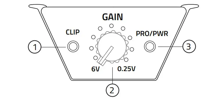
- CLIP: LED indicator for output clipping monitor on the remote Level knob, if you see the light blinking turn it down the Gain.
- GAIN: adjust the output level.
- PRO/PWR: Green light= Power ON, Red light=Protection mode.
SETTING THE GAINS
It is a fact that very few people, including professional installers, know how to set gains correctly. Failure to do so yields higher distortion, a higher noise floor which decreases dynamic headroom, less than optimum operating conditions for electronic equipment, and a higher failure rate for both the electronic equipment and transducers alike.
While most people set this control by ear to how loud they want their music, this is not the intent of this control. The range is from 0. 25 volts to 6 volts. The control is meant for matching the output of the source unit’s signal voltage. For example, if you have a source unit with low output voltage, you would probably have the control set fairly high, towards the O. 25V range.
A lot of head units have 4 volts of output signal voltage which means that your control would be set midway through the range. If you happen to have a line driver (signal booster) that yields 6 volts or more, you will set the gain at the minimum position, towards the 6V range.
In all these examples, when properly level matched, the amplifier will put out the full volume. Setting the control above the improper point may cause damage to the amplifier and speakers and can result in poor sound quality and overall undesirable results.
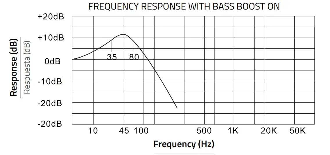
BASS BOOST CONTROL
The monoblock amplifiers feature a variable bass boost control centered at 45Hz.
You can adjust the amount of boost from OdBto 12dB.
MOUNTING YOUR AMPLIFIER
Choosing the best mounting location for your amplifier is crucial. The amplifier should not be mounted to any wood, metal, or carpeted surface. The heatsink can be mounted directly to the chassis of the car, or isolated for best performance. It needs proper ventilation, so avoid mounting the amp under seats, in the engine bay, or in any other area where moisture might accumulate. Be sure the mounting screws do not penetrate the fuel tank, brake lines, or any other crucial fluid lines.
Never mount the amplifier to a subwoofer enclosure, as excessive vibrations can cause damage.
WARNING
We highly recommend that an in-line fuse or circuit breaker be installed within 18″ of the battery. Although your amplifier has adequate internal protection, it is possible a damaged wire between the component and the battery may result in a fire. The in-line fuse or circuit breaker should be installed in a location that is easy to access, and all wiring should be routed safely, following the below suggestions:
- Avoid placing wires near hot or moving objects
- Always use wire grommets when routing wire through the firewall or any other metal surfaces.
- Avoid the potential for damaged wires by routing all wires away from moving hinges, seats, brake & gas pedals, hood and trunk hinges, etc.
Please read carefully before installing or operated this unit high efficiency power amplifier.
WARNING
Make sure you choose a suitable place to mount the unit. The position should be completely dry with a good circulation of air, and from a mechanical point of view very stable.
![]()
POWER CONNECTIONS
It is important to have good quality power and ground connections. Remember, to complete an electrical circuit, the ground connection is just as important as the positive power connection. Before any power connections are made, disconnect the ground cable of the battery. Use 4 gauge or larger automotive grade wire if the distance from the battery to the amp is excessive. Avoid sharp or rough edges as a safeguard against short-circuiting and potential fire hazards.
GND = Connect the proper gauge ground wire to the amplifier GND terminal. Locate the position on the chassis of the car where the amplifier will be grounded. Use solder or a crimped ring terminal to connect the ground wire pre-drill the prepped chassis to bolt the ground ring terminal with a nut, bolt, and lock washer to insulate the metal and the connector with paint or silicone to prevent rust and oxidation. Silicone also works great to prevent nuts and bolts from working loose in the harsh environments of an automobile.
Upon completion of the ground connection, grab the wire end connector to confirm the connection is solid. To prevent engine noise, it is recommended to ground the head unit and other electronic audio devices in the same location.
REM = Connect the remote wire (power antenna output) from the head unit to the REM terminal. If the head unit is not equipped with a remote/antenna output, locale a wire that is controlled by the accessory position of the key. It is important to have the amplifier turn off with the radio or key. If the amplifier remains on, the battery will drain.
12V = Connect the proper gauge power wire to the B+ terminal. Trace the power wire through the car to the in-line fuse or circuit breaker that is no more than 18″ from the battery. Remember, the ln-line fuse or circuit breaker protects the car in the event of a short circuit, connect the in-line fuse or circuit breaker to the battery, but do not install the fuse or activate the circuit breaker yet.
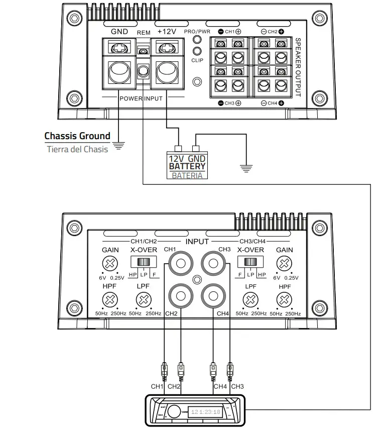
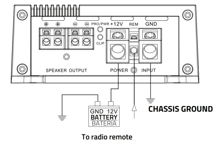
HIGH LEVEL INPUT CONNECTIONS
The high-level inputs are for use with speaker-level wiring. Most factory source units do not have RCA outputs. Use this connection if your source unit does not have RCA outputs.
CAUTION: Never use the high and low-level inputs at the same time!
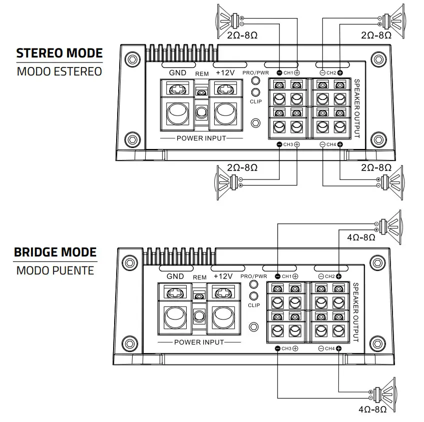
SPEAKER OUT CONNECTIONS
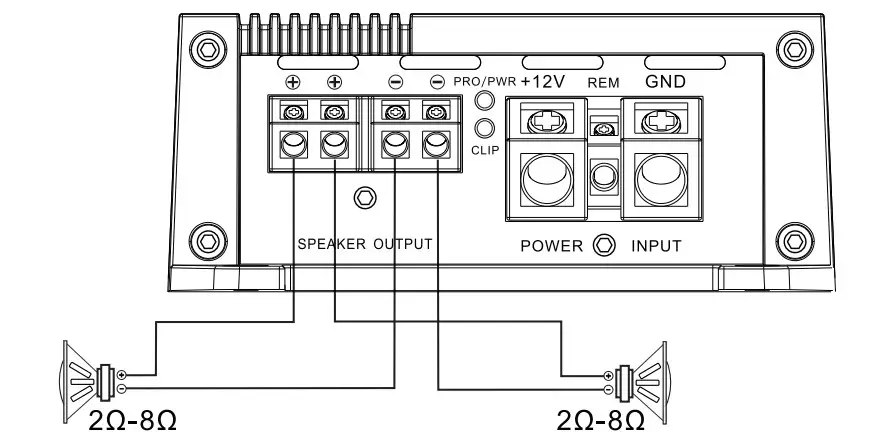
4 Channels speaker connection
SPECIFICATIONS
CLASS D MONOBLOCK SUBWOOFER AMPLIFIER
POWER
| Total Watts (Peak) | 1800 W |
| Rms Power @ 4 OHM | 250 W |
| Rms Power @ 2 OHM | 400W |
| Rms Power @ 1 OHM | 600W |
| Rms Power @ 4 OHM Bridge | – |
AUDIO
| Frequency Response | 10 – 500 Hz |
| Signal To Noise Ratio | >93 dB |
| Efficiency @ 4 OHM | 90% |
| Damping Factor | 54 |
| Input Impedance | 22 K |
| Channel Separation | – |
| Total Harmonic Distortion (THD) | 0.00% |
| Low Level Input Range | 0.25 – 6 V |
| High Level Input | seY |
| Selectable X-over | Fixed LPF |
| X-over Filter Range | 35 – 250 Hz |
| Bass Boost Range | 0 -12 dB |
| Bass Boost Frequency | Fixed @ 45 Hz |
| Infrasonic Filter | 10-50 Hz |
FEATURES
| Amplifier Class | Digital (D) |
| Amplifier Type | Monoblock Subwoofer |
| Subwoofer | |
| Number Of Channels | 1 Ch |
| Minimum Impedance | 1 OHM |
| Led Indicator | Power | Protection | Clip |
| Encendido Recorte | |
| Power Input Terminal Size | 4 GA |
| Fuse Size | 2 X 40 A |
| Remote Level Control | Yes |
| Thermal Protection | Yes |
| Over-Load Protection | – |
| Dc Output Protection | Yes |
| Short Circuit Output Protection | Yes |
| Voltage Input Protection | Yes |
| Clipping Protection | Yes |
| Body Color | Matte Black |
MEASUREMENT
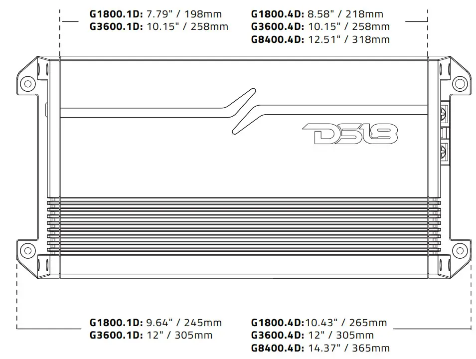
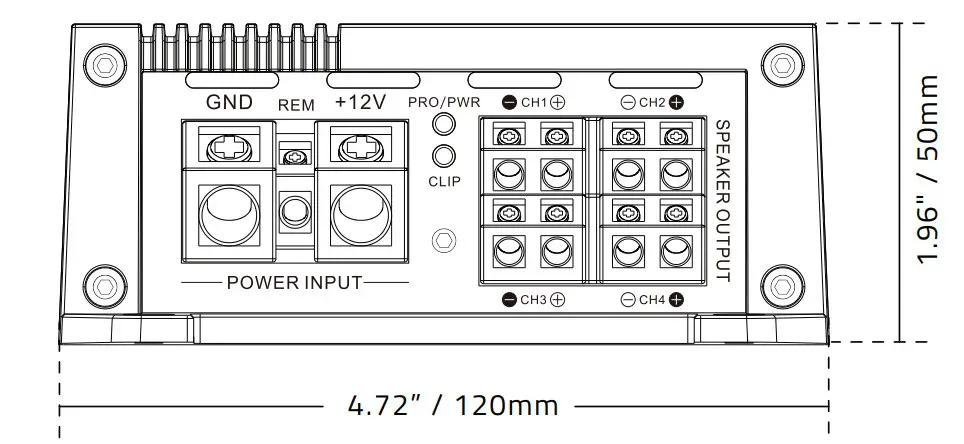
| Overall Length | 9.64″ / 245 mm |
| Overall Wide | 4.72″ / 120 mm |
| Overall Height | 1.96″ / 50 mm |
| Heatsink Length | 7.79″ / 198 mm |
| Gross Single Unit Weight | 1.313 Kg |
TROUBLESHOOTING
| PRODBLEM , | CHECK * | TROUBLESHOOT. |
| No sound | Is the power LED illuminated? (NO) | Check all fuses to amplifier. Be sure turn-on lead is connected Check signal leads. Check gain control. Check Tuner / Deck volume level. Clean contacts en fuse holders. |
| Is the Diagnostic LED illuminated? (YES) | Check for speaker short or amplifier overheating. | |
| Protection lamp on | Shut Down | Turn radio down. Wait for AMP to cool. |
| Speaker wires shorted | Separate speaker wires and insulate |
| PRODBLEM | CHECK | TROUBLESHOOT |
| Ampnot switching on | No power to power wire | Repair power wire or connections. |
| No power to remole wire with receiver on | Check connections to radio | |
| Burnt or broken fuse | Replace fuse | |
| No sound, on one channel | Check speaker leads | Inspect for short circuit or an open connection |
| Check audio leads | Reverse Left and Right RCA inputs to determine if the problem is occurring before the amp. | |
| Amp turning off medium I high volume | Check speaker load impedance | Be sure proper speaker load impedance recommendations are observed (If you use an ohmmeter to check speaker resistance, please remember that DC resistance and AC impedance may not be the same.) |
DIMENSIONS
WARRANTY
Please visit our website DS18.com for more information on our warranty policy.
We reserve the right to change products and specifications at any time without notice.
Images may or may not included optional equipment.
![]()


