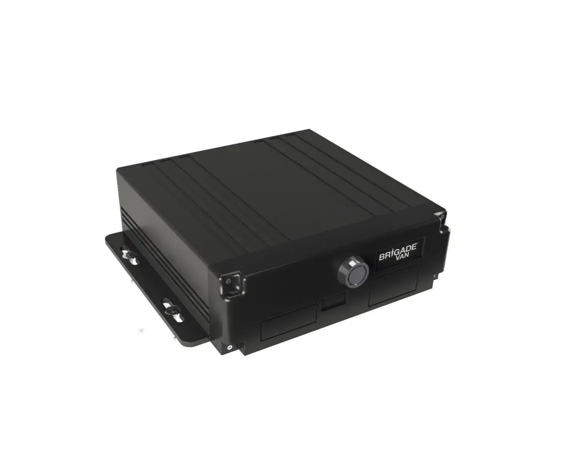
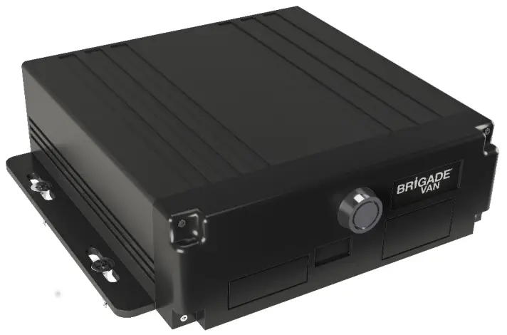
Brigade BL-240D-256-SD SD Card Recorder
Overview
Prior to attempting the system setup, please ensure this guide is thoroughly read and understood. Brigade will not be responsible for any failures due to incorrect installation or operation.
This manual will be updated from time to time without prior notice.
Cautions
Installation Environment
To extend equipment life, please install the equipment in locations with little vibration.
To ensure normal heat dissipation, do not install the device in a poorly ventilated area, make sure the device has good air flow and is kept approximately 15 cm away from other objects on the same level.
The device must be installed horizontally and protected against water, humidity, and lightning. In addition, keep the vehicle stationary during installation to prevent damage to the device due to falling off.
To ensure safe operation, keep the device, camera, cables, and other accessories out of reach of passengers and driver.
Please ensure the MDR power is not connected to the same loom or shared power source of another Telematics device. If the installation requires that the cable is run down the ‘A’-pillar, please make sure this is done down the opposite side to where an existing Telematics device is situated.
Ensure the GPS antenna is not obstructed, installed on top of the unit, in the roof lining or near another GPS antenna.
Avoid electric shock and fire
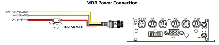
The machine uses 9V-36V DC power supply, be aware of the polarity when wiring to avoid short circuits, take note of the wiring diagram as shown in this document.
Please power off the device when connecting ancillaries.
Do not touch the power and the device with wet hands.
Do not spray liquid on the device to prevent internal short circuit or fire.
Do not place any other equipment on top of device.
Do not disassemble the housing to avoid damage or electric shock, as this will void the warranty.
Transport and operation
Please use original packaging when transporting to avoid damaging the product.
Please turn the power off when moving the device or replacing components.
Product introduction
The 4CH MDR supports 4 channels analogue, audio, video recording and playback.
The product adopts ARM DSP fast dual-core processor running on the Linux embedded OS and integrates the most advanced H.264/H.265 video encoding/decoding in IT industry, 3G/4G network, GPS, as well as power-failure protection, SD shock absorption, wide voltage features.
Main Features:
Supports 4ch Analogue/ AHD 720P/ 1080P cameras
Industry leading CPU with powerful processing ability
Supports SD CARD for recording. Max. 512GB, Class 10 Industrial
Robust design: Cast aluminium enclosure. Patented design
Selected industrial power chipsets, support 9-36V wide range power input, adapt to harsh environment
Support UPS (uninterruptible power source)
Support low/high temperature environment
Dual streams for local recording and network transmission
Support 3G/4G, GPS modules.
Built-in G-sensor for harsh acceleration/deceleration detection/ Driver Behaviour
Data self-protection, save data when shut down abnormally
The unit houses one Secure Digital (SD) card, the SD card is set to overwrite the oldest data first when full. Please note this will need periodic maintenance, which will include being formatted to maintain the health and life span of the SD card; Brigade recommend the SD card is formatted every 30 days.
Do not place upside down
Do not tilt and cover with other objects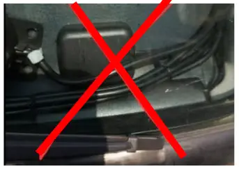
Do not place overMDR
| Power input | DC: +9V ~ +36V | 9V~36V, Check the supply voltage of the vehicle battery before use; If it is supplied with more than36V for a prolonged period, the device may be damaged. |
| Power output | +12V@1A,[email protected] | |
| ACC detection | ≤4V | Power off |
| ≥5V | Power on | |
| Video input impedance | 75Ω | Each video input impedance: 75Ω |
| Video output voltage | 2Vp-p | 2VP-P video output analog signal which shouldbe adapted by 75Ω of input impedance from the display unit. |
| I/O interface | <1V | Low level alarm |
| >5V | High level alarm | |
| Operating temperature | -20℃~70℃ | In a well-ventilated environment |
Kit Contents
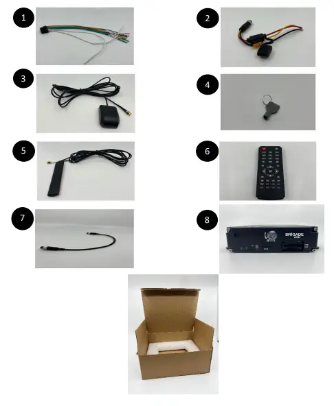
| 1 | Alarm/IO Cable |
| 2 | Power Cable |
| 3 | GPS Antenna |
| 4 | Keys |
| 5 | 3G-4G Antenna |
| 6 | IR Remote |
| 7 | Female to Female cable for monitor connection |
| 8 | BL-240D |
BL-240D-256-SD Ports and Cable label definition
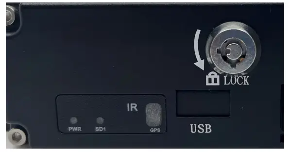
Front Panel
| Interface | Name | Description |
| SIM Card/SIM Card Slot | SIM card slot. SD Card slot. |
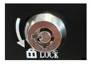
| Lock & Open | Open and lock the door for SD card/SIM card slot; On/off switch for device power |
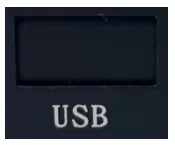
| USB (Behind sliding panel) | For USB mouse, USB flash drive, etc. |
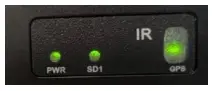
| LED | LED Indicators. Green is on status. SD/HDD LED blinking means it’s recording. |
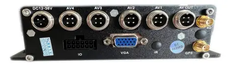
Rear Panel
| Interface | Name | Description |
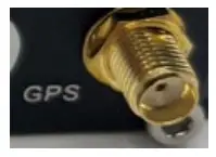
| GPS | Connect with GPS antenna |
| 3G/4G Connection | Connection for 3G/4G antenna |
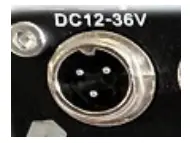
| Power | Connect with power adapter/battery |
| AV OUT | Inset Female to Female cable here |
| AV1 – AV4 | Insert camera input cables here |
| I/O & Serial | For IO cables; Including sensor input, sensor output, DC power output, RS232, RS485, sensor |

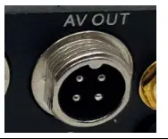 *This AV Output carries power. This means it can power the monitor without the monitor requiring seperate power.
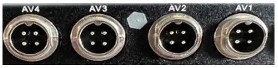
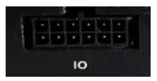
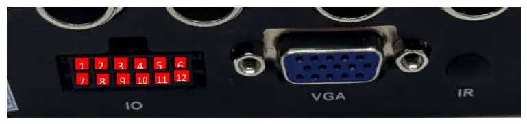
1 | 2 | 3 | 4 | 5 | 6 |
| N/A | RS232-TX | SENSOR-IN4 | SENSOR-IN2 | SENSOR-OUT1 | 12V |
7 | 8 | 9 | 10 | 11 | 12 |
| N/A | RS232-RX | SENSOR-IN3 | SENSOR-IN1 | SENSOR-OUT2 | GND |
Harness Wires
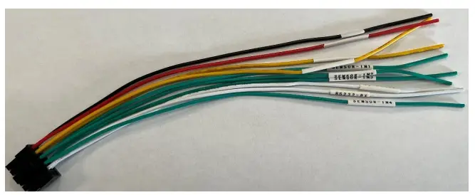
| RED | 12V out |
| BLACK | GD |
| WHITE | TX (Not Required) |
| WHITE | RX (Not Required) |
| YELLOW | SENSOR OUT 1 |
| YELLOW | SENSOR OUT 2 |
| GREEN | SENSOR IN 1 |
| GREEN | SENSOR IN 2 |
| GREEN | SENSOR IN 3 |
| GREEN | SENSOR IN 4 |
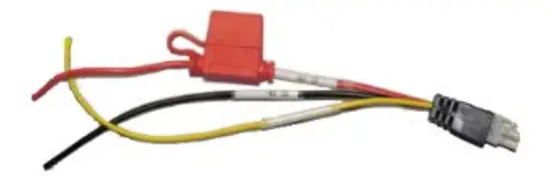
Contains Standard 5A fuse.
LED Status Diagram
| LED | On | Off | Flashing |
| PWR | Power | No Power | N/A |
| GPS | Connected | GPS module not detected | Searching for satellites |
| SD | Detected | Not detected | Recording |
Default screen layout and Alarm input connections
Channel 1 – Left
Channel 2 – Right
Channel 3 – Reverse
Channel 4 – Front
Alarm 1 = Channel 1 (Left)
Alarm 2 = Channel 2 (Right)
Alarm 3 = Channel 3 (Reverse)
Alarm 4 = Channel 4 (Front)
Install process
Once you have received your BL-240D with a SD card and SIM card fitted or separately, if they are in the delivery box, please fit them as shown below.
*Make sure unit is powered off
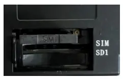
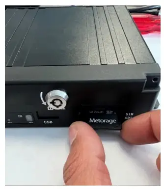
Use key to unlock front of the BL-240D, slide cover to reveal SD card and SIM slot.
Insert SD Card as shown, you will hear a click once this is pushed in fully.
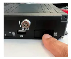
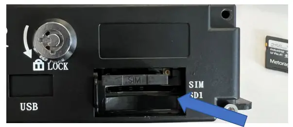
Remove the SIM card holder, to do this push the small button at the top right of the SIM card slot.
Insert SIM card as shown (Face up into SIM holder).
Please make a note of the Sim card number as it is needed for the commissioning process’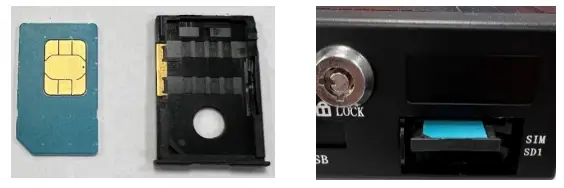
Wire the relevant alarm triggers. Once the above has been installed and powered the BL240D, connect the camera inputs.
Check that the green record LED is showing that the SD card is recording, refer to the LED status diagram If this is not working, please check the SD card is not locked before inserting into the device. If this is still not working, a manual format of the SD card may be required; to do this follow the below steps.
Format
Menu > System Management > Format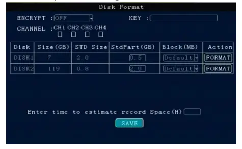
Press the arrow keys to select DISK1 / DISK2 / USB (if you had plugged the USB drive).
It will display the whole available disks. Size/Std size/Block setting.
Encryption: Here the user can set a password (KEY) for the dedicated channels. When played via the player, it will ask the user to Input the password.
STD size: The area for saving Alarm pictures, debug Logs, system file, Alarm videos. For example, if more space if required for saving alarm videos and upload to FTP server, should change it. Just input a new value in StdPart (GB) and SAVE it, then format.
Block (MB): All videos are saving by block read & write technology. It’s not recording by time length.Therefore, if a long time-period video needs to be saved, change a bigger value for it. Format: If there is some error with the disk,
format it. It will take about some minutes.
Login
The default password for admin is 111111; user is 666666
NOTE: To change settings the user will need to enter the Admin password.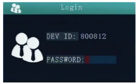
Main Menu > System > Format
Press the arrow keys to select DISK1/USB (if you had plugged the USB drive).
It will display the whole available disks. Size/Std size/StdPart (GB)/Block setting.
Encryption: Here the user can set a password (KEY) for the dedicated channels. When played via the player, it will ask the user to Input the password.
STD Size: The area for saving Alarm pictures, debug logs, system file, alarm videos. E.G – If you need more space for saving alarm videos, uploading to FTP Server will free up space. Input a new value in StdPart (GB) and SAVE it, then format.
Block (MB): All videos are saving by block read & write technology. It’s not recording by time length. So, if a long time- period video needs to be saved, change a bigger value for it.
Format: If there is an error with the disk, ensure format is selected.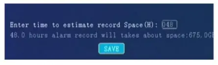
Disk space can also be evaluated for recording
For custom Config on USB, follow the below steps
Main Menu > System > Config, Select Import config
GPS Install location:
The GPS antenna needs to have an unimpeded view to the sky. The antenna positioning and orientation is critical to ensure effective operation. Horizontally mounted on a metal plate is optimum.
Please ensure the GPS antenna is not near another Telematics device, if a cable is required to run down the ‘A’ pillar this is done down the opposite side to where an existing Telematics device is situated.
Calibration Process
The G-Sensor will need to be calibrated on initial install only.
This must be done when the vehicle is stationary and on a flat surface. Main Menu > Alarm > G Sensor.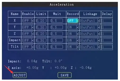
Click on ADJUST to zero the calibration and SAVE to confirm the settings.
Exporting Video Data
Insert the USB stick into the front slot
Alternatively you can remove the SD card and connect to your PC.
Navigate to the Menu > Search > Record select the required date and time and click on Export.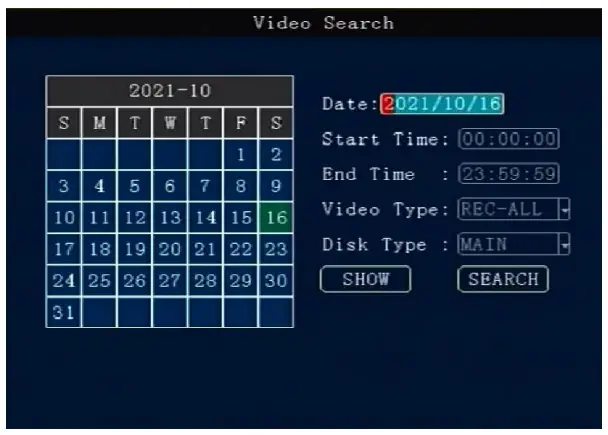
Date: Press number keys on remote to select the date, it defaults for the current day.
Start time: Press number keys to input the time, it defaults for 00:00
End time: Press number keys to input the time, it defaults for 23:59
Video Type: press OK to select: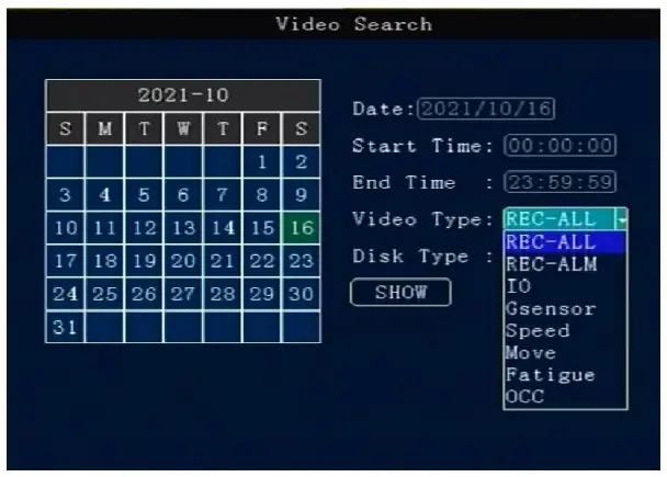
REC – ALL (all type of videos)
REC – ALM (alarm videos) contains
IO – (I/O recording), G sensor, Speed, Move, Fatigue, OCC type. Alarm menu must be set for these to be picked up first.
Disk Type – press the OK button on the remote to select.
Search – Move to the “Search” button, press the OK button on the remote then enter the search results interface.
The interface contains record date, the current page number, menu for browsing, search contents.
In the search contents, it contains: DISK (the file’s location), Type (which is selected), start and end time.
Press the Arrow keys to select the information required to view, press OK button on the remote or click.
PLAY to start playing the video, press the Exit button to return the previous level.
Select the video file required to view and press Ok button to check the video to be backed up.
Pressthe Arrow keys to select “First”, “Previous”, “Next”, “Last”, “Play”, press the OK button to display the information page.
Export: Press the OK button the selected videos will be exported to an external USB storage device.
Note: If the selected period shows no video file, the following interface prompt will be shown: “! This day has no video file’’
http://www.brigade-electronics.com/