
![]() TB3 Series Communicating Thermostats
TB3 Series Communicating Thermostats
FOR 2-PIPE AND 4-PIPE FAN COIL UNITS
INSTALLATION INSTRUCTIONS
APPLICATION
TB3 Series Fan Coil Thermostats are used in individual rooms or zones in buildings. It is designed for two and four-pipe fan coil units. TB3 Series has one universal input as an external sensor (NTC10k) or open/close contact input, three relay fan outputs, two relay valve outputs (TB3140), two analog valve outputs (TB3240), and one EIA-485 (BACnet MS/TP). It controls the fan coil unit depending on the internal room sensor or external return sensor temperature.
The following NTC10K sensor and flange are recommended: VF10-3B65NW and LF-MF![]() CAUTION
CAUTION
- The authorized service must do assembly, maintenance, diagnostic, and repair. The device’s power supply is 220 VAC (TB3140) and 24V AC/DC (TB3240), and it has no internal fuse.
- External protection with max C10A (TB3140) and C5A (TB3240) circuit breakers are required in all cases.
- Disconnect the power supply before separating the front plate.
INSTALLATION
- Read these instructions carefully. Failure to follow them could damage the product or cause a hazardous condition.
- Check the ratings in the instructions and the product to ensure the product is suitable for your application. The Installer must be a trained, experienced service technician.
- After installation is complete, check out product operation as provided in these instructions
- All wiring must agree with applicable codes, ordinances, and regulations, as specified in installation wiring diagrams.
- TB3 Series thermostat safety rules are in accordance with the latest technological developments designed and manufactured. Adhere to the safety precautions to avoid injury and property damage.
![]() CAUTION
CAUTION
Power off the supply at circuit breaker or fuse before installation to avoid fire, shock, or death!
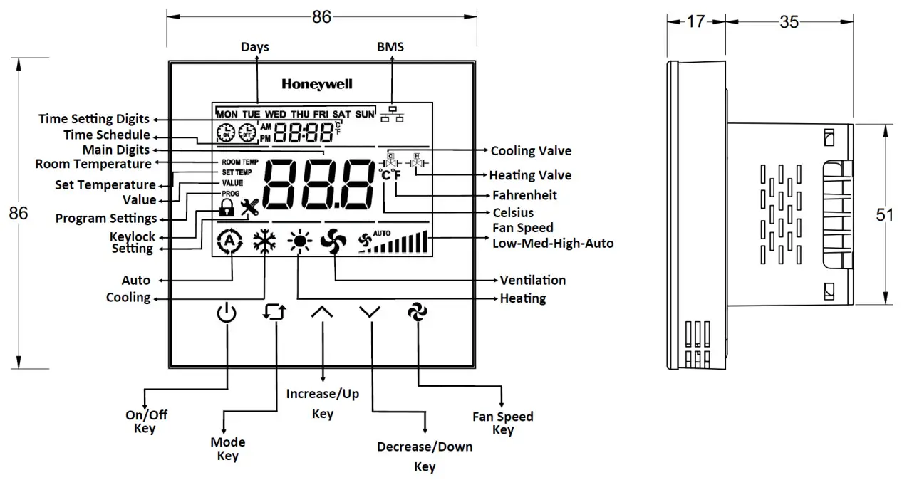
DIMENSIONS AND OVERVIEW
ORDERING INFORMATION
| Part number | TB3240B/U | TB3240W/U | TB3140B/U | TB3140W/U |
| Digital Outputs (Relay) Fan Control | 3 | 3 | 3 | 3 |
| Analog Out puits (0-10V)Value | 2 | 2 | 0 | 0 |
| Relay Output Valve Control | 0 | 0 | 2 | 2 |
| Universal Input | 1 | 1 | 1 | 1 |
| Colour | Black | White | Black | White |
| Power | 24 V AC/DC, 50/60 Hz | 24 V AC/DC, 50/60 Hz | 220 V AC, 50/60Hz | 220 V AC, 50/60 Hz |
PRODUCT SPECIFICATION
Table 1 Display
| Parameter | Specification |
| Display Type | LCD 62 x 44 mm |
| Backlight | White LED |
| Buttons | 5 integrated capacitive touch areas |
| Fascia | Tempered glass |
Table 2 Communication
| Parameter | Specification |
| Communication | 1 x EIA-485(BACnet MS/TP) |
| TIA/EIA 485 Cabling specifications An MSTP EIA-485 network shall use shielded, twisted pair cable. It means the cable is wrapped with a foil or braided copper shield throughout its entire length. By connecting the shield to a single ground point, induced transients should often be reduced and directed to ground. Recommendation : Wire Size: 22-24 AWG Cable Type: Twisted-pair, copper wire, tinned Shield: Braid Nominal Impedance: 100-120 Ohms | |
Table 3 Electrical
| Parameter | Specification |
| Power Supply | TB3240B/TB3240W : 24V AC/DC, 50/60 Hz TB3140B/TB3140W : 100~220 VAC, 50/60 Hz |
| Power Consumption (Display ON) | Max ~3.0 VA |
| Terminal Size | For Power: Up to 16 AWG / 1.5 mm2 For RS485 and NTC: Up to 17 AWG / 1 mm2 |
| Battery for Real Time Clock (RTC) | Lithium CR1220 3.3 V |
Table 4 Sensors and Inputs
| Parameter | Specification |
| Temperature Accuracy | 1 °C (1.8 °F) |
| UI Input Measuring Range | -10 °C to 100 °C (14 °F to 212 °F) |
| Inputs | 1 Universal Input (NTC 10K or Dry Contact) |
| Outputs | 3 Digital Outputs (3 Relay*) 2 Relay Valve Outputs (2 Relay*) (TB3140) 2 Analog Outputs (2 x 0-10 V) (TB3240) (*) 5A for resistive loads and 2A for inductive loads |
Table 5 Operating Environment
| Parameter | Specification |
| Operating Temperature Range | 10 °C to 55 °C (50 °F to 131 °F) |
| Temperature Setting | 5 °C to 40 °C (Adjustable), (41 °F to 104° F (Adjustable) |
Table 6 Other Specifications
| Parameter | Description |
| IP Rating | IP30 |
| Terminal Connections | Rising cage clamp, Screw terminal |
| Standard and Compliance | CE, RoHS, BTL certified (B-ASC) |
| Material of Casing | Flame retardant ABS and Polycarbonate (PC) |
Table 7 Weight and Dimensions
| Parameter | Specification |
| Dimension (L x W x D) | 86 x 86 x 52 mm |
| Weight | TB3140 : 208 grams TB3240 : 207 grams |
| Minimum depth of Wall box | 52 mm |
| Mounting | Flush Mounted (Standard EU box) |
Network Security
Honeywell hereby expressly states that the TB3 Series Communication Thermostat are not inherently protected against all cyber-security risks from the Internet and are thus intended solely for use in private or protected networks.
BACNET and Modbus protocols are open standards with no security.
MOUNTING
The thermostat must be installed indoors, with around 1.5m height above the floor, representing the average room temperature. It should be away from direct sunlight, any cover, or any heat source, to avoid false signals for temperature control. The thermostat should be installed in an area that is not accessible to unauthorized people.
INSTALLATION![]() NOTE:
NOTE:
This Communicating thermostat is suitable for mounting on standard 75 X 75 X 52 mm Honeywell recommended back box as per BS4662:2006 + A1:2009 standard or equivalent.
The installation of the device should be performed by an authorized technician. Install the thermostat using the screws provided in the box.
Steps to Install the TB3 Communicating Thermostat:
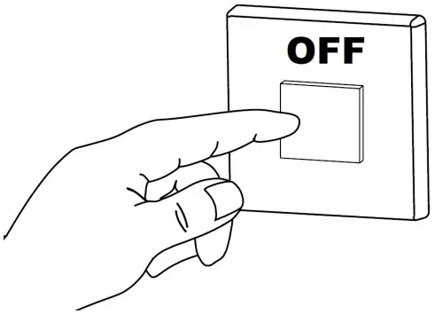
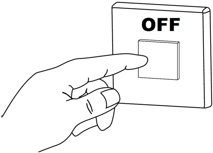
- Switch OFF the power supply before initiating the TB3 installation.

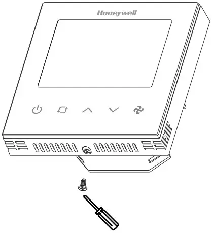
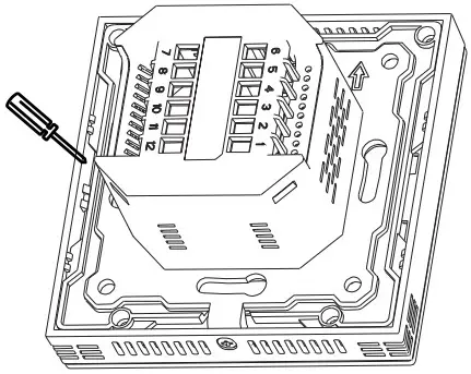
- Loosen the bottom screw by turning it anticlockwise with the help of a screwdriver.

- Separate the front panel and base by pulling out from the bottom to do the wiring.

- Pull the power cable and communication cables through the wall box.
- Connect the wires well according to the wiring diagram. Refer to Wiring Connection on page 6.
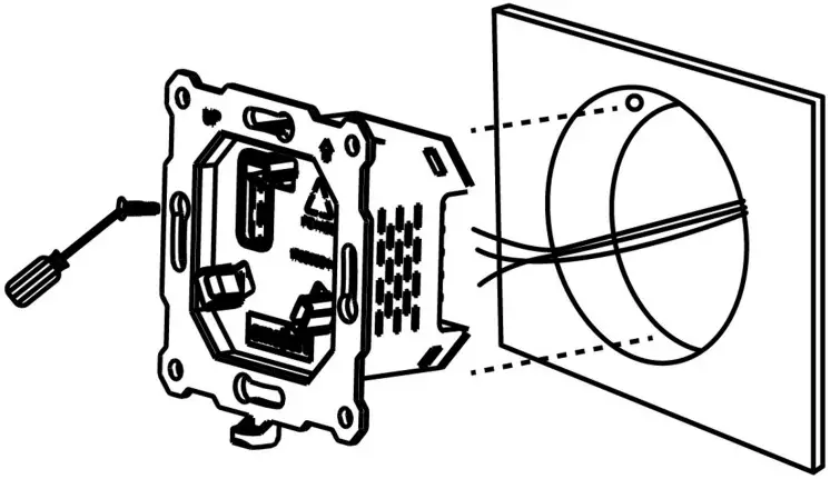
- Fix the base with four screws to the wall box.

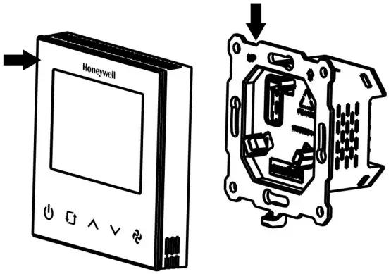
- Attach the front plate to the back plate, making sure the pin plates on each side are well matched.

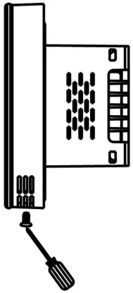
- Tighten the bottom screw to fix the front panel and base.

- Switch ON the power supply to start the TB3 wall module.

WIRING CONNECTION
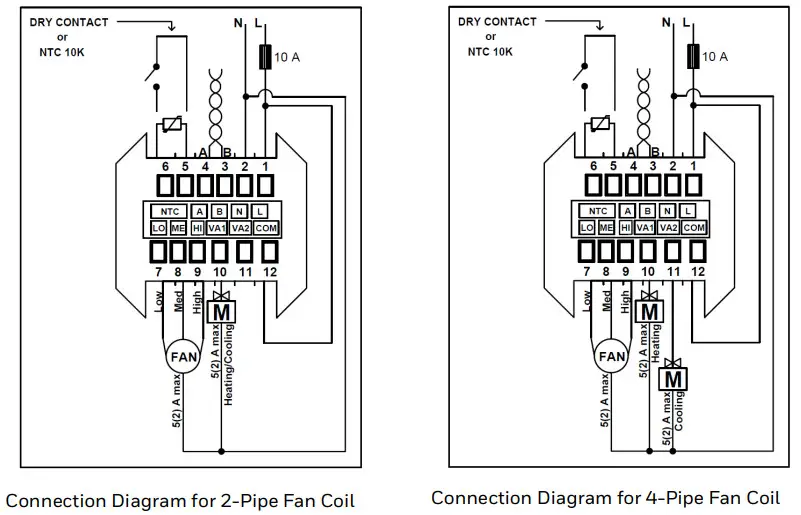
There are two types of modulating connection diagrams. Refer to the wiring diagram that corresponds to the series you are using.
TB3140 Modulating Connection Diagram
TB3240 Modulating Connection Diagram
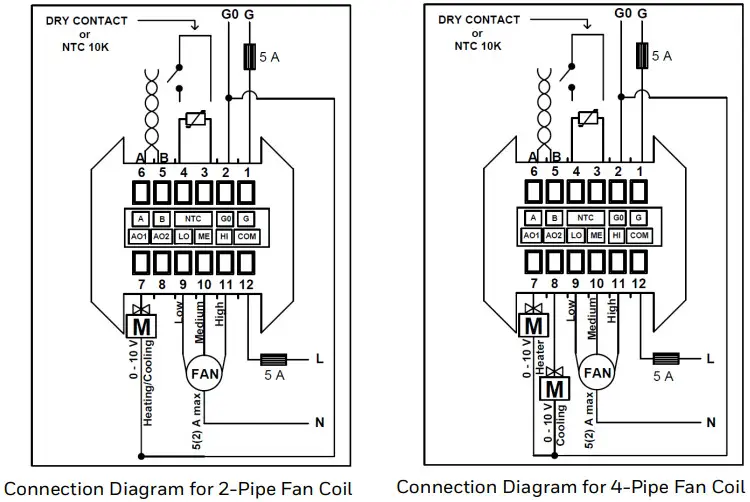
NOTE:
The thermostat has no internal fuse. External protection with max C5 A circuit breaker is required in all cases. Isolate the cables of NTC-dry contact from 230 V(TB3140), 24V AC/DC (TB3240) power supply. The product supply does not include a 5A fuse.
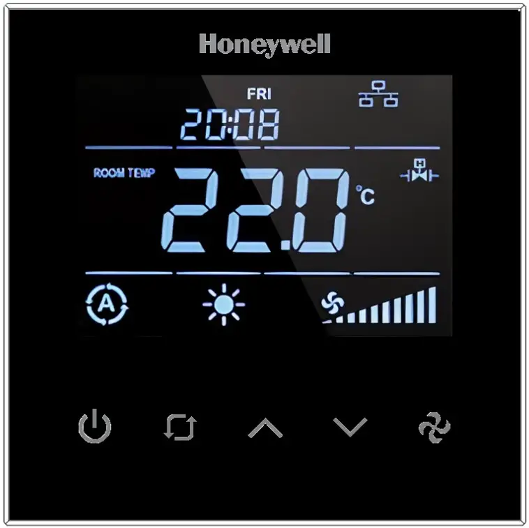
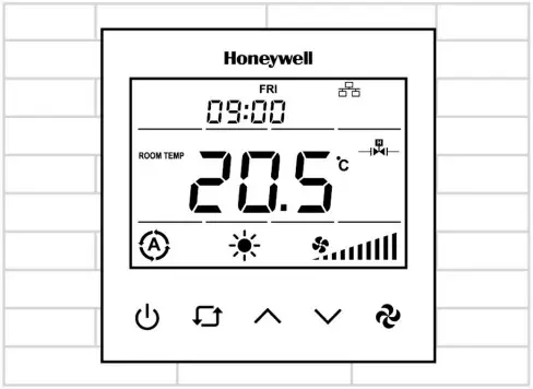
USERS INTERFACE
The TB3 thermostat user interface consists of a multi-segment display and five function keys.
| Name | Key Symbol | Description |
| On/Off Key | Switch device state on/off. | |
| Mode Key | 1. Mode Selection: To change the modes, press the mode key. The modes available for selection will vary depending on the available pipe system. • For 2-Pipe System, modes available are – Cooling, Heating, and Ventilation. • For 4-Pipe System, modes available are – Auto, Cooling, Heating, and Ventilation. NOTE: In 2 pipe systems, the device will operate in the auto mode based on the supply water temperature measured from the changeover sensor if it is selected. In this case, the user will not be able to change the mode. 2. Time Selection: As soon as the mode key is pressed for three seconds, the year will appear on the screen, followed by the month, hour, minute, and day of the week on successive taps. To adjust the required time, use the up and down arrow keys. 3. Schedule Operation: After selecting the day of the week in the time selection, press the mode key again to enter the schedule menu. The sequence of events to configure the schedule is as follows: When in schedule mode, “Monday opening time hour digit” displays > Tap the mode key to enter the edit mode and use up and down to configure the parameter > Tap the mode key again to display “Monday closing time minute digit” > Tap the mode key to enter the edit mode and use up and down to configure the parameter. 4. Key Lock Operation: Pressing the mode key along with the up key displays the lock on the screens and locks the panel. To unlock, press the same combination of keys again. “Key Lock” options can be changed via parameter P6. Refer to the Configuration Menu Parameters on page 12. | |
| Up Key | Increase the set value. | |
| Down Key | Decrease the set value. | |
| Fan Key | Change the fan speed to low, medium, high, and automatic. |
![]() NOTE:
NOTE:
When Time Schedule is enabled, and the Local/Remote selection point is set to “Local Control,” the On/Off button is locked. If “Remote Control” is chosen, the On/Off key will be unlocked even if the user has locked it.
After a certain time, the value of the Local/Remote selection point will be changed to “Local Control.” The user will not be able to change the Key Log value at this time.
TROUBLESHOOTING
| Trouble | Possible Cause | Solution |
| The system is not cooling, even though the set point is correct. | • Use • Check if the set point is lower than room temperature. • Be sure the • After a while, check whether the system starts cooling. | |
| The system is continuously overcooling, even though the set point is correct. | • If the system is continuously over cooling, change the (Mode) to • Please contact your Technical Support if issue persists. Do not select | |
| The system is not heating, even though the set point is correct. | • Use • Check if the set point is higher than room temperature. • Be sure the • After a while, check whether the system starts heating. | |
| The system is continuously overheating, even though the set point is correct. | • If the system is continuously overheating, change the (Mode) to • Please contact your Technical Support if issue persists. Do not select | |
| Keypad doesn’t work / Keys do not respond | Key lock is activated | Press |
| Forgot Password | Contact your system administrator to learn the “Parameter Menu Password” from the communication line. • Please press • Press |
PASSWORD SETTING
![]() IMPORTANT:
IMPORTANT:
It is recommended that a 4-digit pin be set during the first installation. The pin should be kept confidential and should be changed frequently.
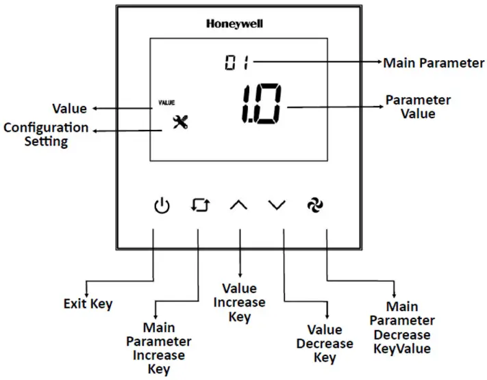
Users must set a password when the thermostat is installed for the first time or restored to factory settings. The thermostat will display a screen to configure the password in these cases. The password digit can be selected usingthe “Main Parameter Increase Key” (Mode Key). The value of that digit can be changed using the “Value Increase Key” (Up key) and “Value DecreaseKey” (Down key). The password entered during the thermostat’s setup must be confirmed with the Fan key.
When the correct password is entered, the configuration menu is displayed. If the incorrect password is entered, the process will fail, and the password will be reset. After 3 incorrect password entries, new password cannot be entered for 180 seconds.
The thermostat returns to the main screen if no action is taken within 10 seconds. In 30 seconds, the parameter setting screen will return to the main screen if no action is taken. All parameters are stored in the device, ensuring no data is lost if the thermostat is turned off.![]() NOTE
NOTE
Password rules
- There can be no blank spaces.
- All digits cannot be the same.
CONFIGURATION
Configuration Menu Description
To enter the Configuration Menu, hold down the “Main Parameter Increase Key” (Mode Key) and the “Value Decrease Key” (Down key) for 3 seconds while the device is urned on or off.
For parameter details refer to the Configuration Menu Parameters on page 12.
Universal Input (P32 or via BACnet)
| Parameter | Definition | Description |
| P32 = 0 | Not Used | The device operates based on the value of the internal temperature sensor. |
| P32 = 1 | External Sensor for room | The device operates based on the value of the external temperature sensor read from the universal input. |
| P32 = 2 | External Sensor | The device operates based on the value of the internal temperature sensor. The temperature read from the universal input can be monitored from P36. |
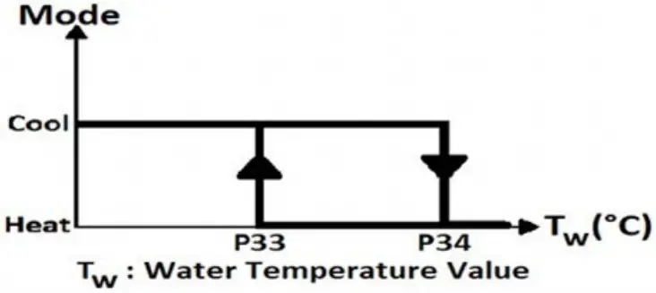
| P32 = 3 | Changeover sensor | If the “Universal Input” value is selected as changeover, “dead zone” cannot be used. The changeover sensor is only valid when the “Fan Coil Type” is set to 2. When the water temperature exceeds P34, the thermostat changes to heating mode and stays in heating mode until the temperature falls below P33. When the water temperature is below P33, the thermostat changes to cooling mode and stays in cooling mode until the temperature rises above P34. |
| P32 = 4 | Windows contact/Energy saving-On/Off (NC Contact) | When this contact is closed, the device will work with normal operation. If this condition is not met, the device displays “OPEN” on the panel, and the device outputs are passive. |
| P32 = 5 | Windows contact/Energy saving-Off/On (NO Contact) | When this contact is opened, the device will work with normal operation. If this condition is not met, the device displays “OPEN” on the panel, and the device outputs are passive. |
Fan/Valve Control Selection (Parameter P41 or via BACnet)
The fan operates in valve-independent mode using manual fan selection or automatic fan control. When the valveis closed, the fan continues to operates.
The fan will not operate in valve-dependent mode when the valve is closed. The fan operates according to manual
fan selection or automatic fan control when the valve is open.
Hysteresis (Parameter P40 or via BACnet)
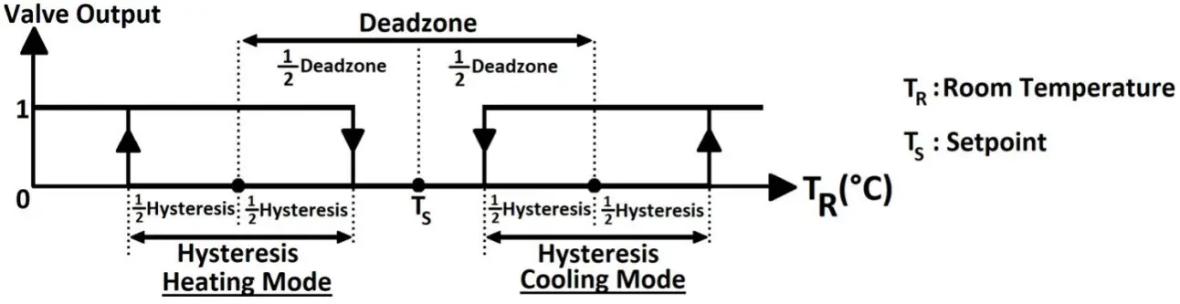
The output diagram of the valve according to the relation between TS and TR
RESTORE FACTORY SETTING
To factory reset the device, press the “On/Off Key,” “Increase/Up Key,” and “Fan Key” together for 5 secondswhile the device is on or off. The “factory settings loading” animation displays for 3 seconds.
ALARMS
An alarm Code will appear on the screen during an alarm. If there is more than one alarm, alarms are shown consecutively.
Onboard Sensor Alarm
The device shows “AL01” on the panel and “Err” on the main digits if the onboard sensor malfunctions.
Device outputs will be closed during the alarm. If the “Universal Input” is set to “External Sensor” during the alarm, the device keeps running normally.
External Sensor Alarm
The device displays “AL02” on the panel and “Err” on the main digits if the “Universal Input” is set to “External Sensor” and the sensor malfunctions.
Device outputs will be closed during the alarm. To turn off the alarm, change the “Universal Input” to “Not Used.”
Changeover Sensor Alarm
The device displays “AL03” on the panel if the “Universal Input” is set to “Changeover Sensor” and the sensor malfunctions.
Device outputs will be closed during the alarm. To turn off the alarm, change the “Universal Input” to “Not Used.”
FIRMWARE UPDATE (FILE OBJECT)
Upload the binary files for a firmware update to the device using a file object.![]() NOTE:
NOTE:
- MS/TP connection need to use directly without any BACnet IP router.
- Upload all txt files provided (4 parts).
- Files can be uploaded regardless of the part number.
![]() IMPORTANT:
IMPORTANT:
- Make sure firmware is upgraded by an authorized user and comes from a genuine source. Scan the firmware for malicious code, if possible. Make sure the firmware and device versions are up-todate.
- Use recommended program for firmware updates.
- Check the parameters from the service menu and BACnet line after the firmware upgrade to be sure the parameters are not affected.
Follow the update status from the “File Transfer Process Information” object:
- When the software update starts, the object’s value is displayed as 1.
- When the software update is successful, the object’s value is displayed as 0 (default value).
- When the software update fails due to any error, the object’s value is displayed as 2.
| NO | NAME OF PARAMETER | PARAMETER DEFINITION | FACTORY DEFAULT |
| P1 | Hardware Version | Device hardware version | 2.1 |
| P2 | Firmware Version | Device firmware version | 2.7 |
| P3 | Setpoint High Limit | Range: 5°C to 40 °C (41 °F to 104 °F) | 30 °C (86 °F) |
| P4 | Setpoint Low Limit | Range: 5°C to 40 °C (41 °F to 104 °F) | 5 °C (41 °F) |
| P5 | Main Screen | 0 = Room temperature 1 = Setpoint temperature 2 = Swap room temperature and setpoint temperature | 0 |
| P6 | Key Lock | 0 = Unlocked 1 = Lock On/Off 2 = Lock mode 4 = Lock setpoint 8 = Lock fan speed 16 = Lock time settings 32 = Lock time schedule settings 63 = Locked all To lock two or more buttons at the same time, add the button values. Enter 12 to lock the setpoint (4) and fan speed (8). | 0 |
| P7 | Celsius or Fahrenheit | 0 = Celsius 1 = Fahrenheit | 0 |
| P8 | Time Format | 0 = 24 hours clock 1 = 12 hours clock (AM/PM) The system time is displayed using a 24-hour clock. This parameter changes how the clock format will appear on the panel or screen. | 1 |
| P9 | Time Schedule Enable | 0 = Disable 1 = Enable | 0 |
| P10 | Screen Saver | 0 = Screen saver disabled 1 = Display On 2 = Display Off 3 = Only room temperature 4 = Room temperature and clock 5 = Swap room temperature and setpoint with clock | 4 |
| P11 | Screen Saver Mode Delay | Range: 10 to 150 seconds | 60 seconds |
| P12 | LCD Brightness | Range: 1 to 5 stage | 5 |
| P13 | Buzzer Stage | Range: 0 to 5 stage | 3 |
| P14 | Power Failure | This parameter adjusts the device’s condition to continue when the power fails. 0 = Device starts off 1 = Device starts on 2 = Keep State Before Power Failure | 2 |
| NO | NAME OF PARAMETER | PARAMETER DEFINITION | FACTORY DEFAULT |
| P15 | Screen Off State Status | 0: Screen off 1: Room temperature 2: Room temperature and off 3: Room temperature and clock | 1 |
| P16(a) | Valve Proportional Band | This parameter determines the output value of the valve proportionally depending on the difference between room temperature and set point. Range: 1 to 100 => 0.1°C to 10°C | 20 |
| P17 to P27 | Reserved | – | – |
| P28 | VA1 Direction | 0 = Direct 1 = Reverse | 0 |
| P29 | VA2 Direction | 0 = Direct 1 = Reverse | 0 |
| P30 | Fan Coil Type | 2 = 2 pipe system 4 = 4 pipe system | 4 |
| P31 | Internal Temperature Sensor Calibration | Range: -10° C to 10 °C and 0.1 °C steps (-18°F to 18°F and 1°F steps) | 0 °C (0 °F) |
| P32 | Universal Input | 0 = Not used 1 = External temperature sensor for the room (NTC 10K) 2 = External Temperature sensor (NTC 10K) 3 = Changeover sensor (NTC 10K) 4 = Windows contact/Energy saving-On/Off (NC Contact) 5 = Windows contact/Energy saving-Off/On (NO Contact) | 0 |
| P33 | Changeover Temperature for Cooling | Range: 10 °C to 25 °C (50 °F to 77 °F). Only valid when P32 is set to 3. | 16 °C (61 °F) |
| P34 | Changeover Temperature for Heating | Range: 26 °C to 45 °C (78 °F to 113 °F). Only valid when P32 is set to 3. | 28 °C (82 °F) |
| P35 | Mode Change Delay | Range: 0 to 255 minutes | 3 minutes |
| P36 | Universal Input Temperature | If P32 is “1”, “2,” or “3”, this parameter shows the sensor temperature. | – |
| P37 | Universal Input Temperature Calibration | Range: -10° C to 10 °C and 0.1 °C steps (-18°F to 18°F and 1°F steps) | 0 °C (0 °F) |
| P38 | Auto Mode Enable | 0 = Disable (Only valid when P30 is set to 4) 1 = Enable | 1 |
| P39 | Dead Zone | Range: 0 °C to 15 °C (0 °F to 27 °F). Only valid when P38 is set to 1 | 2 °C (3 °F) |
| P40 | Hysteresis | Range: 0 °C to 15 °C (0 °F to 27 °F) | 1 °C (1 °F) |
| P41 | Fan/Valve Control Selection | 0 = Valve independent 1 = Valve dependent | 1 |
| P42 | Fan Stage Change Delay | Range: 0 to 5 seconds | 2 seconds |
| P43 | Fan Off Delay | Range: 0 to 60 seconds | 0 seconds |
| P44 | BMS Icon Enable | 0 = Disable 1 = Enable | 1 |
| P45 | Baudrate | 1 = 9600bps 2 = 19200bps 3 = 38400bps 4 = 76800bps | 4 |
| P46 | Loop ID Number | Range: 00 to 99 | 0 |
| NO | NAME OF PARAMETER | PARAMETER DEFINITION | FACTORY DEFAULT |
| P47 | MAC Address | Range: 001 to 127 | 1 |
| P48 | Startup Waiting Time | Range: 0 to 300 | 60 |
(a) Only valid for TB3240x model.
BACnet Parameters
Based on BACnet standard MS/TP port configurations are given below;
8, n, 1 (8 Data Bits, No Parity, 1 Stop Bit)
| Parameter | Range | Default |
| MAC Address | 1 to 127 | 1 |
| Loop Number | 0 to 99 | 0 |
| Baudrate | 9600, 19200, 38400, 76800 | 76800 |
NOTE:
- The MAC address and Loop ID can be changed via configuration menu.
NOTE:
- Device Instance Number (Device ID) is automatically calculated as below.
Device ID = (17 * 100000) + (Loop ID * 1000) + MAC
For example: Loop ID: 1 and MAC: 1 => Device ID = (17 * 100000) + (1 * 1000) + 1 = 1701001
When the MAC address or Loop ID is changed via the configuration menu, the Device ID is automatically recalculated to avoid network ID conflict.
The device ID value is writable via BACnet and ranges from 0 to 4194302 as a property of the device object. Once the Device ID is changed via BACnet, the automatic calculation mentioned above is ineffective. To activate the Device ID automatic calculation again, the device should be factory reset.
Device limit
The RS485 data-link, as a bus topology, requires proper wire type, biasing, and termination to function properly. A maximum of 30 devices is recommended.
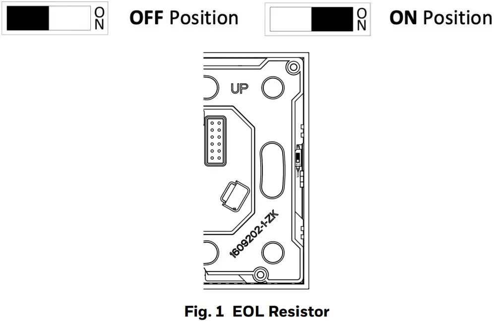
End Of Line (EOL) Resistor
The EOL resistor DIP Switch is located in the top right corner of the TB Series thermostat, behind the front plate. The default is OFF (Left). Turn it to the ON position (Right) to activate the EOL (120 Ohm) resistor.
TB3240 Series BACnet Registers
Analog Inputs
| NO | OBJECT | VALUE | OBJECT NAME | FUNCTION | DEFAULT | READ (R)/ WRITE (W) | COV PROPERTY |
| 1 | Analog Input #1 | -9.9 °C to 99.9 °C (14 °F to 212 °F) | Room Temperature | This parameter shows the room temperature value. | – | R | COV |
| 2 | Analog Input #2 | -9.9 °C to 99.9 °C (14 °F to 212 °F) | Universal Input Temperature | If “Universal Input” is “1”, ’2’’ or “3”, this parameter shows the sensor temperature. | – | R | COV |
Analog Values for TB3140x
| NO | OBJECT | VALUE | OBJECT NAME | FUNCTION | DEFAULT | READ (R)/ WRITE (W) | COV PROPERTY |
| 1 | Analog Value #1 | 0 to 3 | Mode | 0 = Fan Only 1 = Heat 2 = Cool 3 = Auto | 3 | R/W | COV |
| 2 | Analog Value #2 | 1 to 4 | Fan Speed | 1 = Stage 1 2 = Stage 2 3 = Stage 3 4 = Auto | 1 | R/W | COV |
| 3 | Analog Value #3 | Set Point Low Limit to Set Point High Limit | Set Point | This parameter is the desired room temperature value. | 21 °C (70 °F) | R/W | COV |
| 4 | Analog Value #4 | 5°C to 40°C (41°F to 104°F) | Set Point High Limit | This parameter adjusts the high limit for desired room temperature. | 30 ° C (86 °F) | R/W | – |
| 5 | Analog Value #5 | 5°C to 40°C (41°F to 104°F) | Set Point Low Limit | This parameter adjusts the low limit for desired room temperature. | 5 °C (41 °F) | R/W | – |
| 6 | Analog Value #6 | 0 to 63 | Key Lock | 0 = Unlocked 1 = Lock On/Off 2 = Lock Mode 4 = Lock Setpoint 8 = Lock Fan Speed 16 = Lock Time Settings 32 = Lock Time Schedule Settings 63 = Locked All To lock two or more buttons at the same time, add the button values. Enter 12 to lock the setpoint (4) and fan speed (8). | 0 | R/W | – |
| NO | OBJECT | VALUE | OBJECT NAME | FUNCTION | DEFAULT | READ (R)/ WRITE (W) | COV PROPERTY |
| 7 | Analog Value #7 | 0 to 2 | Power Failure | This parameter adjusts the device’s condition to continue when the power fails. 0 = Device starts off 1 = Device starts on 2 = Keep State Before Power Failure | 2 | R/W | – |
| 8 | Analog Value #8 | 2 to 4 | Fan Coil Type | 2 = 2 Pipe System 4 = 4 Pipe System | 4 | R/W | – |
| 9 | Analog Value #9 | -10 °C to 0 °C (-18 °F to 18 °F) | Internal Temperature Sensor Calibration | This parameter adjusts sensor value calibrate with 0.1 °C (1°F) steps. | 0 °C (0 °F) | R/W | – |
| 10 | Analog Value #10 | 0 to 5 | Universal Input | 0 = Not Used 1=External temperature sensor for the room (NTC 10K) 2 = External temperature sensor (NTC 10K) 3 = Changeover sensor (NTC 10K) 4 = Windows contact/Energy saving- On/Off (NC Contact) 5 = Windows contact/Energy saving- Off/On (NO Contact) | 0 | R/W | COV |
| 11 | Analog Value #11 | 10 °C to 25 °C (50 °F to 77 °F) | Changeover Temperature for Cooling | If “Universal Input” is set to “3”, this parameter adjusts the changeover temperature for cooling mode. | 16 °C (61 °F) | R/W | – |
| 12 | Analog Value #12 | 26 °C to 45 °C (79 °F to 113 ° F) | Changeover Temperature for Heating | If “Universal Input” is set to “3”, this parameter adjusts the changeover temperature for heating mode. | 28 °C (82 °F) | R/W | – |
| 13 | Analog Value #13 | 0 to 255 minutes | Mode Change Delay | This parameter adjusts the delay time between the heat and cool modes. | 3 minutes | R/W | – |
| 14 | Analog Value #14 | -10 °C …10 °C (-18 °F…18 °F) | Universal Input Temperature Calibration | This parameter adjusts sensor value calibrate with 0.1 °C (1°F) steps. | 0 °C | R/W | – |
| 15 | Analog Value #15 | 0 °C…15 °C (0 °F…27 °F) | Dead Zone | If “Mode” is set to “Auto”, this parameter adjusts the dead zone. | 2 °C (4 °F) | R/W | – |
| 16 | Analog Value #16 | 0 °C…15 °C (0 °F…27 °F) | Hysteresis | This parameter adjusts the hysteresis. | 1 °C (2 °F) | R/W | – |
| 17 | Analog Value #17 | 0 to 5 second | Fan Stage Change Delay | This parameter adjusts the delay of the changing range of the fan. | 2 second | R/W | – |
| 18 | Analog Value #18 | 0 to 60 second | Fan Off Delay | This parameter adjusts the delay of the closing time of the fan. | 0 second | R/W | – |
| NO | OBJECT | VALUE | OBJECT NAME | FUNCTION | DEFAULT | READ (R)/ WRITE (W) | COV PROPERTY |
| 19 | Analog Value #19 | 0 to 3 | Fan Status | 0 = Off 1 = Low 2 = Med 3 = High | 0 | R | COV |
| 20 | Analog Value #20 | 0 to 3 | Alarm | This parameter indicates the alarm state. 0 = No alarm 1 = Onboard Sensor Alarm 2 = External Sensor Alarm 3 = Changeover Sensor Alarm | 0 | R | COV |
| 21 | Analog Value #21 | 2017 to 2099 | Current Year | This parameter adjusts the current year. | 2022 | R/W | – |
| 22 | Analog Value #22 | 1 to 12 | Current Month | This parameter adjusts the current month. | – | R/W | – |
| 23 | Analog Value #23 | 1 to 31 | Current Day | This parameter adjusts the current day. | – | R/W | – |
| 24 | Analog Value #24 | 00 to 23 | Current Hour | This parameter adjusts the current hour. | – | R/W | – |
| 25 | Analog Value #25 | 00 to 59 | Current Minute | This parameter adjusts the current minute. | – | R/W | – |
| 26 | Analog Value #26 | 1 to 4 | Baud rate | 1 = 9600bps 2 = 19200bps 3 = 38400bps 4 = 76800bps | 4 | R/W | – |
| 27 | Analog Value #27 | 1 to 9998 | Parameter Menu Password. | This parameter adjusts the password. | 0 | R/W | |
| 28 | Analog Value #28 | 0 to 2 | File Transfer Process Information | 0 = Firmware Confirmed 1 = Upload in Progress 2 = Upload Failed | 0 | R |
Analog Values for TB3240x
| NO | OBJECT | VALUE | OBJECT NAME | FUNCTION | DEFAULT | READ (R)/ WRITE (W) | COV PROPERTY |
| 1 | Analog Value #1 | 0 to 3 | Mode | 0 = Fan Only 1 = Heat 2 = Cool 3 = Auto | 3 | R/W | COV |
| 2 | Analog Value #2 | 1 to 4 | Fan Speed | 1 = Stage 1 2 = Stage 2 3 = Stage 3 4 = Auto | 1 | R/W | COV |
| 3 | Analog Value #3 | Set Point Low Limit to Set Point High Limit | Set Point | This parameter is the desired room temperature value. | 21 °C (70 °F) | R/W | COV |
| 4 | Analog Value #4 | 5 °C to 40 °C (41°F to 104°F) | Set Point High Limit | This parameter adjusts the high limit for desired room temperature. | 30 °C (86 °F) | R/W | – |
| NO | OBJECT | VALUE | OBJECT NAME | FUNCTION | DEFAULT | READ (R)/ WRITE (W) | COV PROPERTY |
| 5 | Analog Value #5 | 5°C to 40 °C (41°F to 104°F) | Set Point Low Limit | This parameter adjusts the low limit for desired room temperature. | 5 °C (41°F) | R/W | – |
| 6 | Analog Value #6 | 0 to 63 | Key Lock | 0 = Unlocked 1 = Lock On/Off 2 = Lock Mode 4 = Lock Setpoint 8 = Lock Fan Speed 16 = Lock Time Settings 32 = Lock Time Schedule Settings 63 = Locked All To lock two or more buttons at the same time, add the button values. Enter 12 to lock the setpoint (4) and fan speed (8). | 0 | R/W |
– |
| 7 | Analog Value #7 | 0 to 2 | Power Failure | This parameter adjusts the condition that the device will continue when the power failure. 0 = Device starts off 1 = Device starts on 2 = Keep State Before Power Failure | 2 | R/W | – |
| 8 | Analog Value #8 | 2 to 4 | Fan Coil Type | 2 = 2 Pipe System 4 = 4 Pipe System | 4 | R/W | – |
| 9 | Analog Value #9 | -10 °C to 10 °C (-18 °F to 18 °F) | Internal Temperature Sensor Calibration | This parameter adjusts sensor value calibrate with 0.1 °C (1°F) steps. | 0 °C (0 °F) | R/W | – |
| 10 | Analog Value #10 | 0 to 5 | Universal Input | 0 = Not Used 1=External temperature sensor for room (NTC 10K) 2 = External sensor for room (NTC 10K) 3 = Changeover sensor (NTC 10K) 4 = Windows contact/Energy saving- On/Off (NC Contact) 5 = Windows contact/Energy saving- Off/On (NO Contact) | 0 | R/W | COV |
| 11 | Analog Value #11 | 10 °C to 25 °C (50 °F to 77 °F) | Changeover Temperature for Cooling | If “Universal Input” is set to “3”, this parameter adjusts changeover temperature for cooling mode. | 16 °C (61 °F) | R/W | – |
| 12 | Analog Value #12 | 26 °C to 45 °C (79 °F to 113 °F) | Changeover Temperature for Heating | If “Universal Input” is set to “3”, this parameter adjusts changeover temperature for heating mode. | 28 °C (82 °F) | R/W | – |
| 13 | Analog Value #13 | 0 to 255 minutes | Mode Change Delay | This parameter adjusts the delay time between heat and cool modes. | 3 minutes | R/W | – |
| 14 | Analog Value #14 | -10 °C to 10 °C (-18 °F to 18 °F) | Universal Input Temperature Calibration | This parameter adjusts sensor value calibrate with 0.1 °C (1°F) steps. | 0 °C (0 °F) | R/W | – |
| 15 | Analog Value #15 | 0 °C to 15 °C (0 °F to 27 °F) | Dead Zone | If “Mode” is set to “Auto”, this parameter adjusts the dead zone. | 2 °C (4 °F) | R/W | – |
| 16 | Analog Value #16 | 0 °C to 15 °C (0 °F to 27 °F) | Hysteresis | This parameter adjusts the hysteresis. | 1 °C (2 °F) | R/W | – |
| 17 | Analog Value #17 | 0 to 5 second | Fan Stage Change Delay | This parameter adjusts the delay of the changing range of the fan. | 2 Second | R/W | – |
| 18 | Analog Value #18 | 0 to 60 second | Fan Off Delay | This parameter adjusts delay of the closing time the fan. | 0 Second | R/W | – |
| 19 | Analog Value #19 | 0 to 3 | Fan Status | 0 = Off 1 = Low 2 = Med 3 = High | 0 | R | COV |
| 20 | Analog Value #20 | 1 to 100 | Valve Proportional Band | This parameter determines the fan’s output value proportionally depending on the difference between Room Temperature and Set Point. Range: 0.1°C to 10°C | 20 | R/W | COV |
| 21 | Analog Value #21 | 0 to 100 | VA1 State | 0 V to 10 V | 0 | O | COV |
| 22 | Analog Value #22 | 0 to 100 | VA2 State | 0 V to 10 V | 0 | O | COV |
| 23 | Analog Value #23 | 0 to 3 | Alarm | This parameter indicates the alarm state. 0 = No alarm 1 = Onboard Sensor Alarm 2 = External Sensor Alarm 3 = Changeover Sensor Alarm | 0 | R | COV |
| 24 | Analog Value #24 | 2017 …2099 | Current Year | This parameter adjusts the current year. | 2022 | R/W | – |
| 25 | Analog Value #25 | 1 to 12 | Current Month | This parameter adjusts the current month. | – | R/W | – |
| 26 | Analog Value #26 | 1 to 31 | Current Day | This parameter adjusts the current day. | – | R/W | – |
| 27 | Analog Value #27 | 00 to 23 | Current Hour | This parameter adjusts the current hour. | – | R/W | – |
| 28 | Analog Value #28 | 00 to 59 | Current Minute | This parameter adjusts the current minute. | – | R/W | – |
| 29 | Analog Value #29 | 1 to 4 | Baudrate | 1 = 9600bps 2 = 19200bps 3 = 38400bps 4 = 76800bps | 4 | R/W | – |
| 30 | Analog Value #30 | 1 to 9998 | Parameter Menu Password. | This parameter adjusts the password. | 0 | R/W | – |
| 31 | Analog Value #31 | 0 to 2 | File Transfer Process Information. | 0 = Firmware Confirmed 1 = Upload in Progress 2 = Upload Failed | 0 | R | – |
Binary Inputs
| NO | OBJECT | VALUE | OBJECT NAME | FUNCTION | DEFAULT | READ (R)/ WRITE (W) | COV PROPERTY |
| 1 | Binary Input #1 | 0 to 1 | Universal Input Digital Input Value | 0 = Off 1 = On | – | R | COV |
Binary Values for TB3140x
| NO | OBJECT | VALUE | OBJECT NAME | FUNCTION | DEFAULT | READ (R)/ WRITE (W) | COV PROPERTY |
| 1 | Binary Value #1 | 0 to 1 | Start/Stop | 0 = Stop 1 = Start | 1 | R/W | COV |
| 2 | Binary Value #2 | 0 to 1 | Celsius or Fahrenheit | 0 = Celsius 1 = Fahrenheit | 0 | R/W | – |
| 3 | Binary Value #3 | 0 to 1 | Auto Mode Enable | 0 = Disable 1 = Enable | 1 | R/W | COV |
| 4 | Binary Value #4 | 0 to 1 | Fan/Valve Control Selection | 0 = Valve Independent 1 = Valve Dependent | 1 | R/W | – |
| 5 | Binary Value #5 | 0 to 1 | VA1 Status | 0 = Valve Closed 1 = Valve Opened | – | R | COV |
| 6 | Binary Value #6 | 0 to 1 | VA2 Status | 0 = Valve Closed 1 = Valve Opened | – | R | COV |
| 7 | Binary Value #7 | 0 to 1 | Restore Factory Setting | 0 = Factory Setting Disable 1 = Factory Setting Started | 0 | R/W | – |
| 8 | Binary Value #8 | 0 to 1 | Time Schedule Local/Remote Selection | 0 = Time Schedule Local Selected 1 = Time Schedule Remote Selected Parameter will be returned to 0 after 30 minutes for security. | 0 | R/W | – |
Binary Values for TB3240x
| NO | OBJECT | VALUE | OBJECT NAME | FUNCTION | DEFAULT | READ (R)/ WRITE (W) | COV PROPERTY |
| 1 | Binary Value #1 | 0 to 1 | Start/Stop | 0 = Stop 1 = Start | 1 | R/W | COV |
| 2 | Binary Value #2 | 0 to 1 | Celsius or Fahrenheit | 0 = Celsius 1 = Fahrenheit | 0 | R/W | – |
| 3 | Binary Value #3 | 0 to 1 | Auto Mode Enable | 0 = Disable 1 = Enable | 1 | R/W | COV |
| 4 | Binary Value #4 | 0 to 1 | Fan/Valve Control Selection | 0 = Valve Independent 1 = Valve Dependent | 1 | R/W | – |
| 5 | Binary Value #5 | 0 to 1 | Restore Factory Setting | 0 = Factory Setting Disable 1 = Factory Setting Started | 0 | R/W | – |
| 6 | Binary Value #6 | 0 to 1 | Time Schedule Local/Remote Selection | 0 = Time Schedule Local Selected 1 = Time Schedule Remote Selected Parameter will be returned to 0 after 30 minutes for security. | 0 | R/W | – |
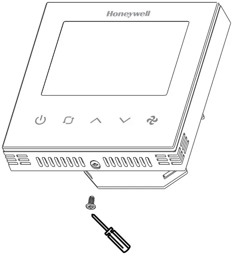
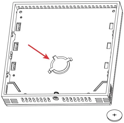
SAFE BATTERY REMOVAL
| 1. Switch OFF the power supply before initiating the TB3 installation. | 2. Loosen the bottom screw by turning it anticlockwise with the help of a screwdriver. |
 |  |
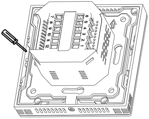
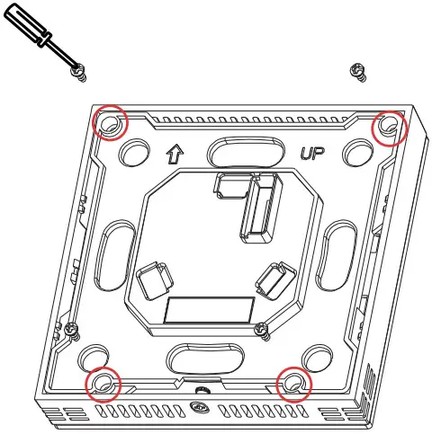
| 3. Separate the front and back plate. | 4. Unscrew four screws to remove the back cover from the front plate. |
 |  |
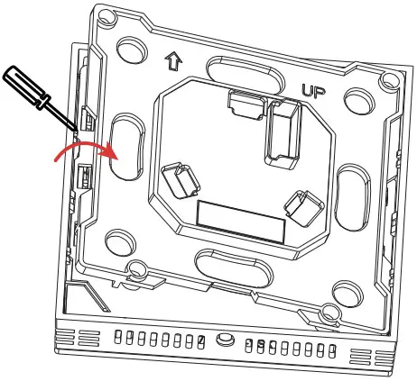
| 5. Using a screwdriver, gently release four latches. | 6. Remove the battery from the battery holder and replace the battery. |
 |  |
 WEEE DIRECTIVE
WEEE Directive 2012/2019/EC Waste Electrical and Electronic Equipment Directive.
- At the end of the product life dispose of the packaging and product in a corresponding recycling center.
- Do not dispose of the unit with the usual domestic refuse.
- Do not burn the product.
The material in this document is for information purposes only. The content and the product described are subject to change without notice.
Honeywell makes no representations or warranties with respect to this document. In no event shall Honeywell be liable for technical or editorial omissions or mistakes in this document, nor shall it be liable for any damages, direct or incidental, arising out of or related to the use of this document. No part of this document may be reproduced in any form or by any means without prior written permission from Honeywell.
Honeywell Building Technologies
715 Peachtree St NE
Atlanta, Georgia 30308
buildings.honeywell.com
® U.S. Registered Trademark
©2022 Honeywell International Inc.
31-00576-01 I Rev. 11-22


