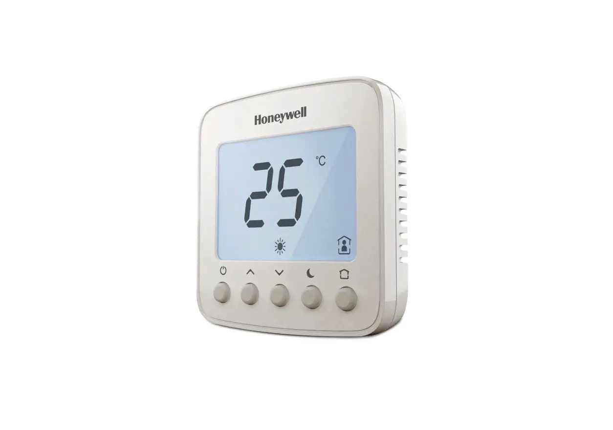
Honeywell Home TF428WNM/U Communicating Thermostat User Manual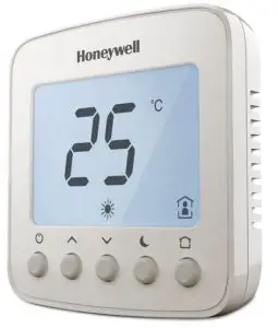
Operating Your Thermostat
![]() Power on/Off
Power on/Off![]() Time OFF
Time OFF
- Press
 to switch on/off thermostat. When in off mode, “OFF” icon will display.
 - Press
 could set the automatical turn off time when the thermostat is working. Press and hold for more than 3s. After timer icon flashes, press
  or
or  to set turn off time, then press 0 button to save and exit.
Temperature Setting
In ![]() or
or ![]() or
or ![]() mode, press
mode, press![]() or
or ![]() to set the target room temperature.
to set the target room temperature.
Operating Mode
- Ventilation

- Heating

- Cooling
- Auto


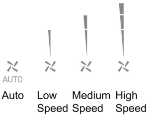
![]() Fan Speed
Fan Speed
LCD DISPLAY


Trouble Shooting Tips
| If…. | Then…. |
| · Set the mode to · Make sure the temperature is set above the room temperature. · Make sure · Wait 5 minutes for the system to respond. | |
| · Set the mode to :i: (cooling mode) by press . Make sure the temperature is set below the room temperature. · Make sure · Wait 5 minutes for the system to respond. | |
| · Make sure keypad is unlocked. · Check the thermostat is on. | |
| · Make sure keypad is unlocked. – Make sure the system isn’t in · Check the thermostat is on. — | |
| The system turns off automatically | .Make sure the memorized turn off time value isn’t set to Ir. |
| Display | · Check the Modbus address and Baud rate, use master to read registers. · Check the wiring. |
| 4 Pipes Valve doesn’t work | -Check 151J setup. · Check the wiring. |
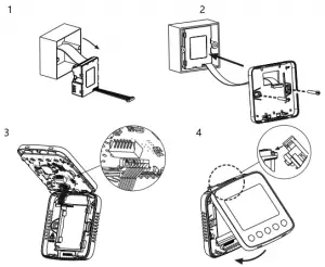
Installation Guide
Must be installed by a trained and experienced installer
Read instruction carefully. Failure to follow instruction will damage the product or cause a hazardous condition.
Caution: ELECTRICAL HAZARD can cause electrical shock or equipment damage. Disconnect power before installation, reparation and detachment.
Installation Tips
TF428WNM/U is designed for standard 75x75x50mm wall mounting box . Install the thermostat about 5 feet (1.5m) above the floor in an area with good air circulation at average temperature.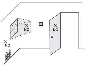
Do not install in locations where the thermostat can be affected by:
- Dead spots behind doors and in corners
- Not or cold air from ducts
- Sunlight or radiant heat from appliances
- Concealed pipes or chimneys
Wiring and Installation
The screw must be locked tightly to avoid wire break off from the terminal. The wire should not be tangled and stucked between front case assembly and back case.
Request Shielded Twisted Pair(STP) wire for R5485 communication. Separate the low voltage and high voltage wiring. Max 32 pcs in one loop, do not connect to unauthorized devices. Select proper terminal resistor based on application environment.
Modbus Requirements
| Physical layer | EIA485 |
| Protocol | Master-Slave |
| Baud rate | 9600 (Default) /4800/19200 |
| Parity | None |
| Signal Transmission | RTU |
| Error Checking Mechanism | CRC |
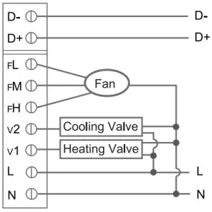
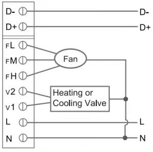
Terminal Designations
| Terminal | Symbol | Description |
| 1 | D- | Modbus 485- |
| 2 | D+ | Modbus 485+ |
| 3 | FL | Low speed fan |
| 4 | EM | Medium speed fan |
| 5 | FH | High speed fan |
| 6 | V2 | 2-pipe-VC6013:Valve close 4-pipe-VC4013:Cooling Vavle open |
| 7 | v1 | 2-pipe-VC4013NC6013:Valve open 4-pipe-VC4013:Heating Vavle open |
| 8 | L | Live wire |
| 9 | N | Neutral wire |
The temperature of mounting box and wall should be in the operating temperature range.
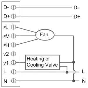
VC401 3/VN401 3NS401 6 Wiring (2-pipe)
VC6013/VN6013 Wiring(2 pipe)
VC4013/VN4013VS4016 Wiring(4 pipe)
ISU (INSTALLATION SETUP)
Enter or exit Installation Setup Mode
| ISU | Description | Options |
| 0 | Modbus Address | 1-64 1(Default) |
| 1 | System Type | 0-Heat only |
| 1-Cool only | ||
| 2-2-pipe manual (Default) | ||
| 4-4-pipe manual | ||
| 5-4-pipe auto change over | ||
| 2 | Temperature Scale | 0-°F 1-°C (Default) |
| 3 | Fan Control Type | 0-Auto only |
| 1-Manual only (3 speed: Low –,Med->High-.Low) | ||
| 2-Users can choose auto or cycle (Default) | ||
| 4 | Switching Differential For 4-pipe Auto Changeover Eith Single Set point | 1°C (2°F) |
| 1.5°C (3°F) (Default) | ||
| 2°C (4°F) | ||
| 3°C (5°F) | ||
| 5 | CPH Value (Heat) | 1-12 4(Default) |
| 6 | CPH Value (Cool) | 1-6 3(Default) |
| 7 | Display Temperature Adjustment | -2-2°C, Step 0.5°C 0°C (Default) ( -4-4° F, Step 1°F 0°F (Default)) |
| 8 | Temperature Display | 0-Room temperature (Default) |
| 1-Setpoint | ||
| 9 | Heating Range Stops | 10-32 °C32 °C (Default) (50-90 °F 90 °F (Default)) |
| 10 | Cooling Range Stops | 10-32 °C 10 °C (Default) (5090°F 50 °F (Default)) |
| 11 | Keypad Lockout | 0-All keys are available (Default) |
| 1-System button is locked | ||
| 2-Fan and System button are locked | ||
| 3-All buttons are locked except power button | ||
| 4-All buttons are locked | ||
| 12 | Freeze Protection | 0-Disable 1–Enable (Default) |
| 13 | Power Recovery Status | 0-OFF 1-Previous status (Default) |
| 14 | Modbus Baud rate | 0-Baudrate 9600 (Default) |
| 1-Baudrate 4800 | ||
| 2-Baudrate 19200 |
NOTE: When the thermostats are integrated into building automation system, user is able to change the setting value above in “Communicating Parameter Setting” list as well.
Communicating Parameter Setting
When the thermostat is integrated into building automation system, you can make configuration refer below list.
| Addr | Configuration Parameters | Significance and adjustment | Properties |
| 1 | Power | 0-OFF; 1-ON | R/W |
| 2 | Room Temp | Room temperature | R |
| 3 | Temperature Scale | 0-°F; 1-°C | R/W | |
| 4 | Setpoint | Setpoint | R/W | |
| 5 | Fan S peed | 0-Auto; 1-Low speed; 2-Med speed; 3-High speed | RNV | |
| 6 | System Mode | 0-Ventilation; 1-Heat; 2-Cool; 3-Auto | R/W | |
| 7 | V1 Valve Status | 0-Closed; 1-Open | R | |
| 8 | V2 Valve Status | 0-Closed; 1-Open | R | |
| 9 | Error Code | 0-None; 1-Sensor; 2-EEprom; 3-Sensor+EEprom | R | |
| 10 | Fan Operation Status | 0-Off; 1-Low speed; 2-Med speed: 3-High speed | R | |
| 25 | Time Off Time | 0-12; Unit: hour | RAN | |
| 26 | Remain Time To Turn Off | 0-12; Unit: hour | R | |
| Internal settings (User is able to change the setting value of below parameters on site, see details in “ISU” part) | ||||
| 11 | Address | 1-64 1 (Default) | R/W | |
| 12 | System Type | 0-Heat only; 1-Cool only; 2-2-pipe heating/cooling manual(Default);4-4-pipe manual; 5-4-pipe Auto changeover | R/W | |
| 13 | Fan Control Type | 0-Auto; 1-Manual; 2-Auto+Manual (Default) | RAN/ | |
| 14 | Switching Differential For 4-Pipe Auto Change Over With Single Setpoint | 2-1°C (2°F); 3-1.5 °C (3°F) (Default); 4-2°C (4°F); 5-3°C (5°F) | RNV | |
| 15 | CPH Valve For Heat | 1-12 4 (Default) | R/W |
| 16 | CPH Valve For Cool | 1-6 3 (Default) | R/W |
| 17 | Dis play Temp . Adjustment | 0-8 ( -2-2°C ) Step 1 (0.5°C) 4 (Default) 0-8 ( -4-4°F ) Step 1 (1°F) 4 (Default) | R/W |
| 18 | Temp. Display | 0-Room Temp.(Default); 1-Setpoint | R/W |
| 19 | Heating Range Stops | 100-320 (10-32°C) Step 5 (0.5°C) 320 (Default) (50-90°F) Step 10 (1°F) 900 (Default) R/W | |
| 20 | Cooling Range Stops | 100-320 (10-32°C) Step 5 (0.5°C) 100 (Default) 500-900 (50-90°F) Step 10 (1°F) 500 (Default) | Fuw |
| 21 | Keypad Lockout | 0-All Keys are available (Default) | R/W |
| 1-System button locked | |||
| 2-Fan and system button locked | |||
| 3-All button locked except power button | |||
| 4-All button are locked | |||
| 22 | Freeze Protection | 0-Disable; 1-Enable (Default) | R/W |
| 23 | Power Recovery Status | 0-OFF; 1-Previous status (Default) | R/W |
| 24 | Modbus Baudrate | 0-9600 (Default); 1- 4800; 2-19200 | R/W |


