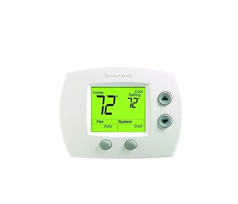
Honeywell 5000 Series Thermostat
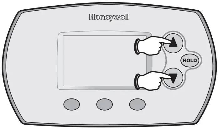
INSTALLER SYSTEM TEST
FocusPRO®5000 Series
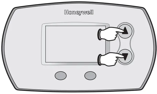
- To begin, press and hold the ▲ and ▼ buttons until the display changes.

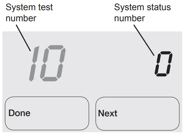
- Press ▲/▼ to turn system on/off

- Press NEXT to advance to next test.
- Press DONE to terminate system test.
- Proceed to Installer System Tests on page 8.
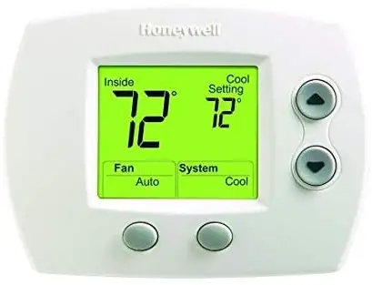
FocusPRO® 6000 Series
- To begin, press and hold the ▲ and ▼ buttons until the display changes

- Press▲/▼t to turn system on/off.

- Press NEXT to advance to next test.
- Press DONE to terminate system test.
- Proceed to Installer System Tests on page 8.
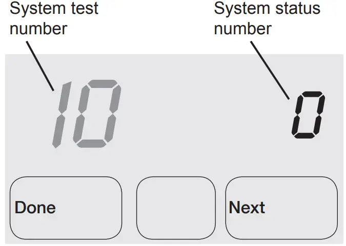
INSTALLER SYSTEM TESTS
Test the system’s heating, emergency heat, cooling, and fan.
Available tests vary by thermostat and system type
Table 2. Installer System Test | ||
| System Test Number | Test Type | System Status Number and Description |
| 10 | Heating system |
|
| 20 | Emergency heating system |
|
| 30 | Cooling system |
|
| 40 | Fan system |
|
CAUTION
EQUIPMENT DAMAGE HAZARD.
Compressor protection is bypassed during testing.
To prevent equipment damage, avoid cycling the compressor quickly
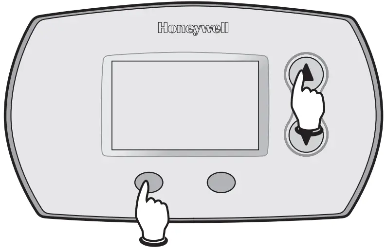
INSTALLER SETUP
FocusPRO® 5000 Series
- To begin, press and hold the ▲ and FAN buttons until the display changes.

- Press ▲ or ▼to change settings

- Press NEXT to advance to the next function.
- Press DONE to exit and save settings.
- Proceed to Installer Setup Functions on page 4.
FocusPRO® 6000 Series
- To begin, press and hold the ▲ and FAN buttons until the display changes.

- Press ▲ or ▲ to change settings.

- Press NEXT to advance to the next function.
- Press DONE to exit and save settings.
- Proceed to Installer Setup Functions on page 4.
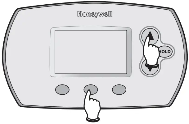
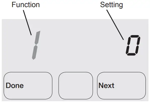
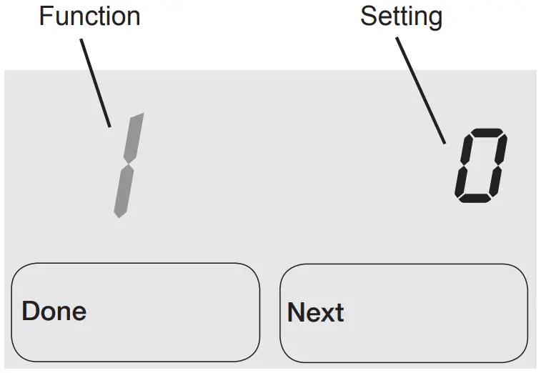
Table 1. Installer Setup | ||
| Setup functions | Setting & Options (factory default in bold) | |
| 1 | System type |
|
| 2 | Changeover valve (O/B terminal) |
|
| 3 | Fan control (heating) | 0 Gas/Oil heat (equipment controls heating fan) 1 Electric furnace (thermostat controls heating fan) |
| 5 | First stage heat cycle rate | 5 Gas or oil furnaces of less than 90% efficiency 1 Steam or gravity |
| 6 | Second stage heat/Aux heat cycle rate | 5 Gas or oil furnaces of less than 90% efficiency 1 Steam or gravity 3 Hot water systems or furnaces of 90%+ efficiency 9 Electric furnaces [Other options: 1–12] |
| 7 | Auxiliary heat cycle rate | 5 Gas or oil furnaces of less than 90% efficiency 1 Steam or gravity 3 Hot water systems or furnaces of 90%+ efficiency 9 Electric furnaces [Other options: 1–12] |
| 8 | Emergency heat cycle rate | 9 Electric emergency heat 1 Steam or gravity 3 Hot water systems or furnaces of 90%+ efficiency 5 Gas or oil furnaces of less than 90% efficiency [Other options: 1–12] |
| 9 | First stage compressor cycle rate | 3 Recommended [Other options: 1–6 |
| 10 | Second stage compressor cycle rate | 3 Recommended [Other options: 1–6] |
| 12 | Manual/Auto changeover | 0 Manual changeover (Heat/Cool/Off) 1 Auto changeover (Heat/ Cool/Auto/Off) 2 Auto changeover only (Auto) |
| 13 | Adaptive Intelligent Recovery TM | 1 On 0 Of |
| 14 | Temperature display | 0 Fahrenheit 1 Celsius |
| 15 | Compressor protection | 5 5-minute compressor off time [Other options: 0–4 minutes] |
| 16 | Schedule format | 0 5/2 (weekdays and weekends programmable) 1 5/1/1 (weekdays, Saturday, and Sunday programmable) |
| 26 | Auxiliary heat control | 0 Comfort 1 Economy |
| 27 | Heat temperature range stops | 90 Max. heat temperature setting is 90°F (32°C) [Other options: 40–89°F (4.5°C to 32°C)] |
| 28 | Cool temperature range stop | 50 Min. cool temperature setting is 50°F (10°C) [Other options: 51–99°F (10.5°C to 37°C)] |
Functions 13 and 16 only available on the 6000 series; function 26 only available on the 5000 series
Printed in U.S.A. on recycled paper containing at least 10% post-consumer paper fibers.
Automation and Control Solutions
Honeywell International Inc. 1985 Douglas Drive North Golden Valley, MN 55422
Honeywell Limited-Honeywell Limited
35 Dynamic Drive Toronto, Ontario M1V 4Z9
http://yourhome.honeywell.com
® U.S. Registered Trademark
© 2006 Honeywell International Inc.
US Patent No. 6595430, D509151; other
Patents Pending. All Rights Reserved 69-2026 M.S. 09-06


")


