Honeywell 8000 VisionPRO Thermostats Instruction Manual
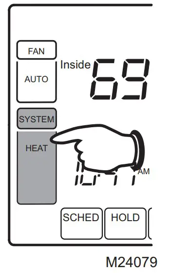
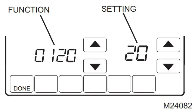
Installer setup
- Press SYSTEM.

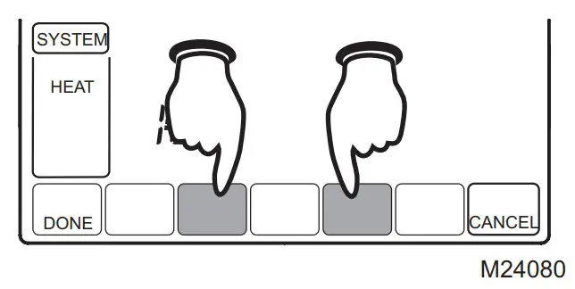
- Press and hold these two blank buttons until the display changes.

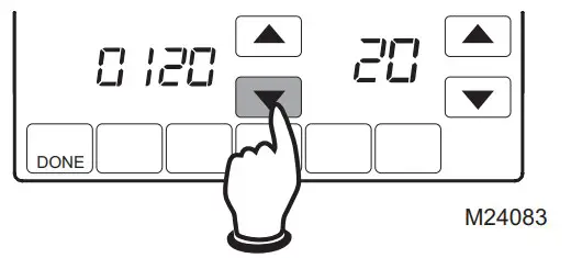
- Use arrows to change settings as required.

- Press DONE to exit and save settings.
Installer setup functions
Available option and default settings vary by thermostat.
| Table 1. Installer Setup | ||
| Setup functions | Setting & Options (factory default in bold) | |
| 0120 | Year (first two digits) | 20 (2000-2099) 21 (2100-2178) |
| 0130 | Year (second two digits) | 06 (2006) [Other options 0-99] |
| 0140 | Month | 6 [Other options 1-12] |
| 0150 | Day | 15 [Other options 1-31 |
| 0160 | Schedule format | 4 7-day programming 0 Non-programmable |
| 0170 | System type | 1 1 heat / 1 cool Conv. 2 1 heat / 1 cool heat pump (no Aux. heat) 3 Heat only (2 wire) 4 Heat only with fan 5 Hot water Series 20 6 Cool only 7 2 heat / 1 cool heat pump (with Aux. heat) 8 2 heat / 2 cool multistage 9 2 heat / 1 cool multistage 10 1 heat / 2 cool multistage 11 2 heat / 2 cool heat pump (no Aux. heat) 12 3 heat / 2 cool heat pump (with Aux. heat) |
| 0180 | Fan control (heating) | 0 Gas/Oil heat (equipment controls heating fan) 1 Electric furnace (thermostat controls heating fan) |
| 0190 | Changeover valve (O/B terminal) | 0 Controls valve in cooling 1 Controls valve in heating |
| 0200 | Auxiliary heat | 0 Electric backup heat 1 Fossil fuel backup heat |
| 0210 | External fossil fuel kit | 1 External fossil fuel kit controls backup heat 0 Thermostat controls backup heat (outdoor sensor required) |
| 0220 | First stage compressor cycle rate | 3 Recommended [Other options: 1–6] |
| 0230 | Second stage compressor cycle rate | 3 Recommended [Other options: 1–6] |
| 0240 | First stage heat cycle rate | 5 Gas or oil furnaces of less than 90% efficiency 1 Steam or gravity 3 Hot water systems or furnaces of 90%+ efficiency 9 Electric furnaces [Other options: 1–12] |
| 0250 | Second stage heat cycle rate | 5 Gas or oil furnaces of less than 90% efficiency 1 Steam or gravity 3 Hot water systems or furnaces of 90%+ efficiency 9 Electric furnaces [Other options: 1–12] |
| 0260 | Third stage heat cycle rate | 9 Electric auxiliary heat or electric furnaces 1 Steam or gravity 3 Hot water systems or furnaces of 90%+ efficiency 5 Gas or oil furnaces of less than 90% efficiency [Other options: 1–12 |
| 0270 | Emergency heat cycle rate | 9 Electric auxiliary heat or electric furnaces 1 Steam or gravity 3 Hot water systems or furnaces of 90%+ efficiency 5 Gas or oil furnaces of less than 90% efficiency [Other options: 1–12] |
| 0280 | Backlight | 0 Backlight on keypress 1 Continuous backlight (requires 24VAC connection |
| 0300 | Manual/auto changeover | 0 Manual changeover (Heat/Cool/Off) 1 Automatic changeover (Heat/Cool/Auto/Off) |
| 0310 | Auto changeover deadband | 3 Heat/cool temperature 3°F apart (1.5°C) [Other options: 2-9 (2°F9°F/1°C-5°C)] |
| 0320 | Temperature display | 0 Fahrenheit 1 Celsius |
| 0330 | Daylight savings | 1 Auto-change to daylight savings time (through 2006) 2 Auto-change to daylight savings time (2007 and beyond) 0 Daylight savings time is turned off |
| 0340 | Remote sensor | 0 No remote sensor 1 Outdoor sensor (display only) 2 Outdoor sensor for control (select heat pumps) 3 Indoor sensor |
| 0350 | Heat pump compressor lockout | 0 Off [Other options: 15, 20, 25, 30, 35, 40°F (-9.5°C to 7°C)] |
| 0360 | Heat pump auxiliary lockout | 0 Off [Other options: 40, 45, 50, 55, 60°F (4.5°C to 15.5°C)] |
| 0380 | Dehumidification Control | 0 Off 1 A/C runs to help dehumidify |
| 0500 | Furnace filter change reminder | 0 Off 1 10-day run time (about 1 month) 2 30-day run time (about 3 months) 3 60-day run time (about 6 months) 4 90-day run time (about 9 months) 5 120-day run time (about 1 year) 6 365-day run time (about 3 years) |
| 0510 | Humidifier pad change reminder | 0 Off 1 90 calendar days 2 180 calendar days 3 365 calendar days |
| 0520 | U/V lamp change reminder | 0 Off 1 365 calendar days |
| 0530 | Adaptive Intelligent RecoveryTM | 1 On 0 Off |
| 0540 | Program periods | 4 4 periods (Wake, Leave, Return, Sleep) 2 2 periods (Wake, Sleep) |
| 0580 | Compressor protection | 5 5-minute compressor off time [Other options: 0–4 minutes] |
| 0600 | Heat temperature range stop | 90 Max. heat temperature setting is 90°F (32°C) [Other options: 40-89°F (4°C to 32°C)] |
| 0610 | Cool temperature range stop | 50 Min. cool temperature setting is 50°F (10°C) [Other options: 51-99°F (11°C to 37°C)] |
| 0640 | Clock format | 12 12-hour time 24 24-hour time |
| 0650 | Extended fan timer (heat) | 0 Off 90 Fan runs for 90 seconds after call for heat ends |
| 0660 | Extended fan timer (cool) | 0 Off 90 Fan runs for 90 seconds after call for cooling ends |
| 0670 | Keypad Lockout | 0 Unlocked 1 Partially locked 2 Fully locked |
| 0680 | Heat temperature control | 2 Standard temperature control (recommended) 1 Select if inside temperature is consistently over setting 3 Select if inside temperature is consistently under setting |
| 0690 | Cool temperature control | 2 Standard temperature control (recommended) 1 Select if inside temperature is consistently over setting 3 Select if inside temperature is consistently under setting |
| 0700 | Temperature display offset | 0 No offset [Other options: -3, -2, -1, 1, 2, 3°F (-1.5°C to 1.5°C)] |
| 0710 | RESET | 0 No reset 1 Reset installer options & program schedule to factory default |
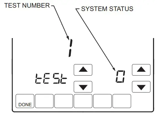
INSTALLER SYSTEM TEST
The Installer Test is part of the Installer Setup Menu.
- Enter the Installer System Test by entering the Installer Setup and pressing t repeatedly until “Test” appears.

- Use arrow to change test and system status as required.

- Press DONE to exit.
System tests
Test the system’s heating, cooling, fan and emergency heat. Available tests vary by thermostat and system type.
| Table 2. Installer System Test | ||
| System Test Number | Test Type | System Status Number and Description |
| Test 1 | Cooling System Test | 0 Off 1 Compressor and fan on 2 Second stage compressor on |
| Test 2 | Fan System Test | 0 Off 1 Fan on |
| Test 3 | Heating System Test | 0 Off 1 Heat on 2 Second stage heat (Aux. heat) on 3 Third stage heat (Auxiliary heat) on |
| Test 4 | Emergency Heat Test | 0 Off 1 Em. Heat and fan on 2 Auxiliary heat on |
| Press the DONE button to exit the Installer System Test. | ||
Caution
EQUIPMENT DAMAGE HAZARD. Compressor protection is bypassed during testing. To prevent equipment damage, avoid cycling the compressor quickly
 Printed in U.S.A. on recycled
paper containing at least 10%
post-consumer paper fibers.
Automation and Control Solutions
Honeywell International Inc.
1985 Douglas Drive North
Golden Valley, MN 55422
Honeywell Limited-Honeywell Limitée
35 Dynamic Drive
Toronto, Ontario M1V 4Z9
http://yourhome.honeywell.com
® U.S. Registered Trademark
© 2006 Honeywell International Inc.
US Patent No. 6595430, D509151; other
Patents Pending. All Rights Reserved
69-1871-1 M.S. Rev. 09-06


