
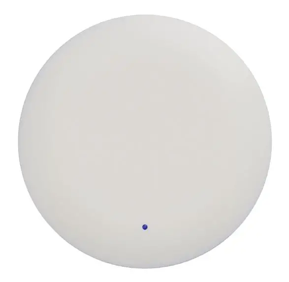
walkbase XR-2 0.6kg Sensor
Revision history
| Version number | Changes | Date | Person |
| 1.0 | First release | 15 Mar 2021 | VK |
Specifications
| HARDWARE SPECIFICATIONS | |
| Model | XR-2 |
| Dimensions | 250 x 250 x 54 mm |
| Dimensions with mounting plate | 250 x 250 x 54 mm |
| Weight | 0.6 kg |
| IP protection class | IP20 |
| Power supply | PoE |
| PoE standard | 802.3af |
| Operating frequency range | 2.4-2.5GHz and 5.1-5.9GHz,2402-2480MHz |
| Power consumption | <8 W |
| Certification | CE, FCC, RoHS |
| Working temperature | 0 – 45°C with unobstructed airflow |
| Ceiling mount material | Stainless steel |
| Housing material | PC/ABS |
| Package dimensions | 332 x 336 x 73 mm |
| Package weight | TBD |
| Package contents | 1x Walkbase XR-2 sensor |
| 1x Ceiling mount | |
Dimensions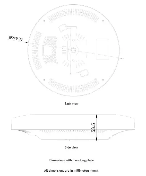
Mounting plate dimensions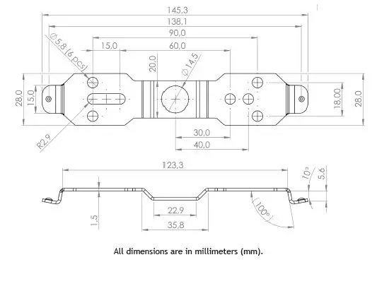
Installation
- The device should be mounted horizontally with the frontside of the device facing towards the floor directly underneath the device. Make sure there is no more than 5° of tilt in any direction.
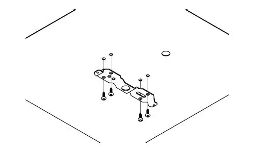
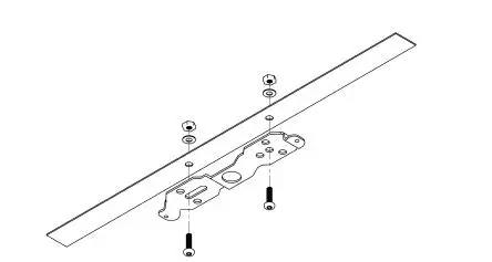
- Fasten the mounting plate onto the ceiling structures using the holes in the plate, and prepare a hole in the ceiling for the Ethernet cable if needed.

- Example mounting onto a flat surface using four screws.

- Example mounting onto metal railing using two fastening bolts.
- Example mounting onto a flat surface using four screws.
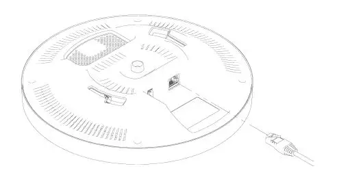
- Insert the Ethernet cable. There will be an audible click when the cable has been properly inserted. The XR-2 starts automatically with the cable inserted, and requires no user interaction.

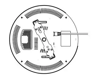
- Attach the XR-2 to the ceiling mount.

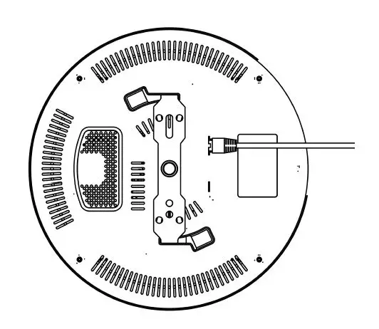
- Gently push the XR-2 in with both of the ceiling mount’s extrusions slotting into the grooves of the XR-2 as shown below. The XR-2 fits the mount plate in either orientation, but the device orientation should not be changed after the device has been configured.

- Twist the XR-2 clockwise until there is an audible click and it locks into the position shown above.

- Gently push the XR-2 in with both of the ceiling mount’s extrusions slotting into the grooves of the XR-2 as shown below. The XR-2 fits the mount plate in either orientation, but the device orientation should not be changed after the device has been configured.
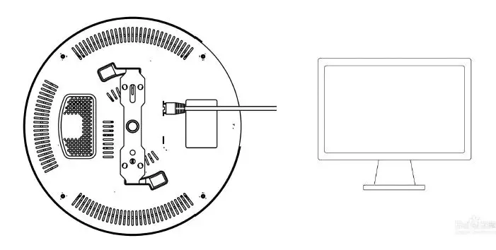
- When the product is connected to the network cable, the indicator lights up and enters the working state. The XR-2 is connected to the switch.
- There are two main chips inside this product
- AI7697HD Module monitors BLE 4.2 and IEEE 802.11 traffic and receives external WIFI and Bluetooth signals (e.g., mobile phone, Bluetooth headset, etc.).
- After receiving the WIFI and Bluetooth signals within the range, the relevant data will be stored in the server.
- This module does not have a transmitting function only receiving function
- BG22 SOC is a Bluetooth tag locator that appears in the detection area. When a Bluetooth locator appears in the monitoring range.BG22 SOC sends and receives data from the corresponding
- Bluetooth small board locator. The data is eventually transferred to the server for archiving.
- The positioning of this product is the data collection function.BG22 SOC is designed to record the location of bluetooth tags.
- AI7697HD Module is to collect WIFI and Bluetooth signals in the use range.
FCC Statement
This equipment has been tested and found to comply with the limits for a Class B digital device, pursuant to part 15 of the FCC Rules. These limits are designed to provide reasonable protection against harmful interference in a residential installation. This equipment generates, uses and can radiate radio frequency energy and, if not installed and used in accordance with the instructions, may cause harmful interference to radio communications. However, there is no guarantee that interference will not occur in a particular installation. If this equipment does cause harmful interference to radio or television reception, which can be determined by turning the equipment off and on, the user is encouraged to try to correct the interference by one or more of the following measures:
- Reorient or relocate the receiving antenna.
- Increase the separation between the equipment and receiver.
- Connect the equipment into an outlet on a circuit different from that to which the receiver is connected.
- Consult the dealer or an experienced radio/TV technician for help.
Caution: Any changes or modifications to this device not explicitly approved by the manufacturer could void your authority to operate this equipment. This device complies with part 15 of the FCC Rules. Operation is subject to the following two conditions: (1) This device may not cause harmful interference, and (2) this device must accept any interference received, including interference that may cause undesired operation.
RF Exposure Information
This equipment complies with FCC radiation exposure limits set forth for an uncontrolled environment. This equipment should be installed and operated with minimum distance 20cm between the radiator and your body.


