![]()
Parking sensor installation instructions
Product Summary
| Type | Part name | External dimensions (mm) | quality (g) | Power supply |
| G— Parking sensor | NDPM003 US | Ф200mm K35.6mm | 600 | 1Built-in primary battery |
| Place of use | Do not use on iron plate, Above ground, outdoors, underground, asphalt, concrete | |||
| Set location | In parking frame | |||
| Waterproof performance | IP67 | |||
| Operating temperature limit | —4O?~65ºc? | |||
| Notes | Please note that it cannot be detected correctly under the following conditions ➀ seawater, under snow, an environment where organic solvent may splash, iron plate on top of the sensor | |||
| Material name | ||||
| Shipping material | TOP COVER ASSY | 1 | 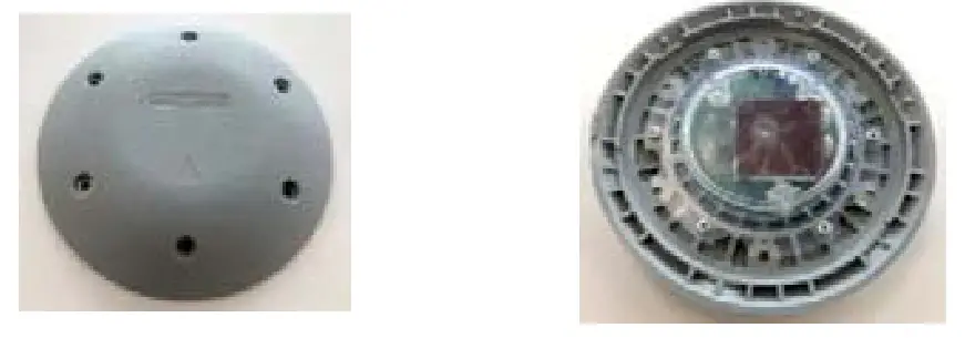 | |
| KOUSING | 1 | 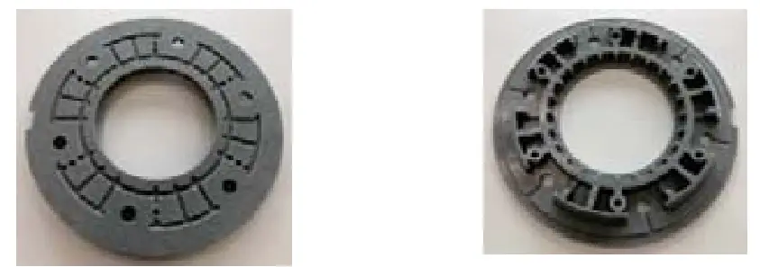 | ||
| SCREW (Ф5 × 16mm) | 6 | 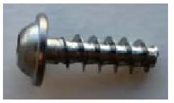 | ||
| Materials prepared by the customer | ADHESIVE FOR SCREW | FOR 6–SCREW | 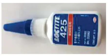 | |
| NEODYMIUM MAGNET | 1 | 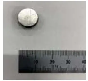 | ||
| ANCHOR BOLT (Ф10) SCREW BOLT (Ф7) | 6sets | 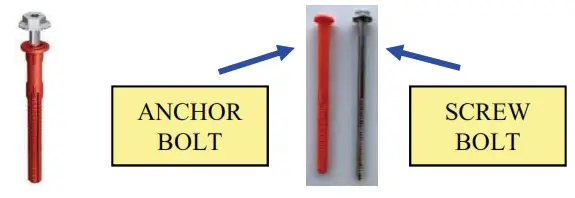 | ||
Mounting method
| NO | Content | |
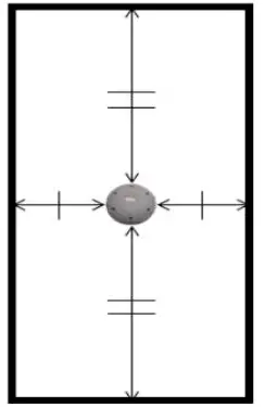
| 1 | Set location please install the parking sensor in the center of the parking frame | /parking frame
|
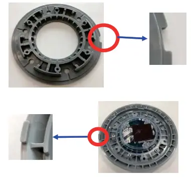
| 2 | Set face Drilling 1. Align the mark engraved on the HOUSING in the direction of vehicle parking (Photo A Red circle) 2. At this time, the ANCHOR BOLT hole position of HOUSING is misaligned with the installation direction. (Photo B ,Blue circle 6 places | 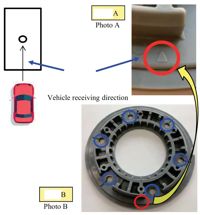 |
| 3 | HOUSING fixed After making holes on the installation surface, attach in the following order. | 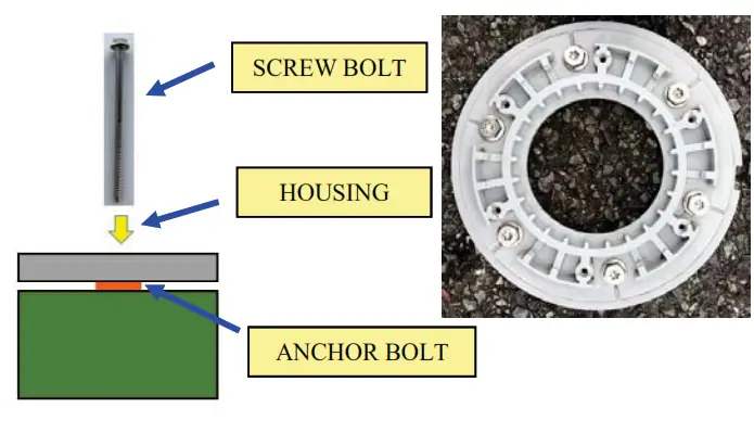 |
| NO | Content | |
| 4 | Operation check 1.Looking inside the TOP COVER ASSY, look so that the mounting guide convex (*) is on the left (*) (Photo C2) | 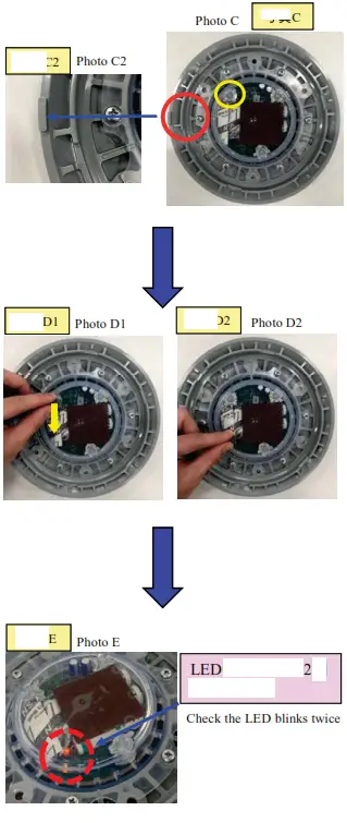 |
| NO | Content | |
| 5 | TOP COVER ASSY Wearing the TOP COVER ASSY
|  |
| 6 | SCREW Fasten with SCREW1.Apply the prescribed SCREW locking adhesive to the SCREW (pictured) 2. Fasten the adhesive-applied SCREW to the six SCREW holes on the TOP COVER. 3. SCREW tightening torque is Please set at 2.10N m (210cN m) | 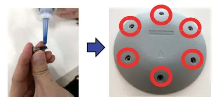 |
| 7 | Installation completed | 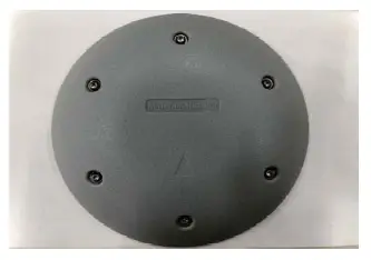 |
![]() FCC
FCC
Notation related to FCC specifications
FCC ID: 2AWRLNDPM003US
•Product: Parking Sensor
•Model THE: NDPM003 US
This device complies with part 15 of the FCC Rules. Operation is subject to the following two conditions:
(1) This device may not cause harmful interference, and (2) this device must accept any interference received, including interference that may cause undesired operation.
•FCC CAUTION
Changes or modifications not expressly approved by the party responsible for compliance could void the user’s authority to operate the equipment.
- This transmitter must not be co-located or operated in conjunction with any other antenna or transmitter.
- This equipment complies with FCC radiation exposure limits set forth for an uncontrolled environment and meets the FCC radio frequency (RF) Exposure Guidelines. This equipment should be installed and operated keeping the radiator at least 20cm or more away from the person’s body.
Note: This equipment has been tested and found to comply with the limits for a Class B digital device, pursuant to part 15 of the FCC Rules. These limits are designed to provide reasonable protection against harmful interference in a residential installation. This equipment generates, uses and can radiate radio frequency energy and, if not installed and used in accordance with the instructions, may cause harmful interference to radio communications. However, there is no guarantee that interference will not occur in a particular installation. If this equipment does cause harmful interference to radio or television reception, which can be determined by turning the equipment off and on,
the user is encouraged to try to correct the interference by one or more of the following measures:
- Reorient or relocate the receiving antenna.
- Increase the separation between the equipment and receiver.
- Connect the equipment into an outlet on a circuit different from that to which the receiver is connected.
- Consult the dealer or an experienced radio/TV technician for help.
Contact for US area
-NMB Technologies Corporation
Address :9730 Independence Ave, Chatsworth, CA 91311
Tel:805-657-2578
Email: [email protected]


