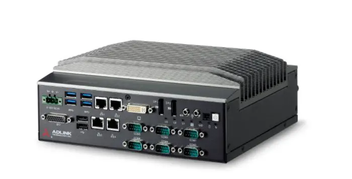
ADLINK R4600 GEN2 Communication Control System

NDL requirements
Power
Floating wide range DC input to support EN50155:2017 and ignition input to control system power plus initiate graceful operating system shutdown. The ignition control signal is to be referenced to input supply voltage as requested by NDL and is detailed in Section 2 Product Specifications. A flow diagram is shown under 6.2 power ignition control.A TVS diode is fitted between the plus and minus power inputs, there are no voltage clamping devices between these inputs and the chassis. A standard 1000VAC voltage withstand test with shorted plus – minus is supported.
From EN 50155:2017:-
Voltage withstand test
| Nominal battery voltage and/or I/O voltage | Test voltage |
| 72 V DC ≤ V DC < 125 V DC or from 50 to 90 V AC rms | 1 000 V AC or 1 500 V DC |
Expansion
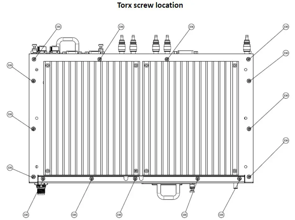
The unit is equipped with four mPCIe slots, two m.2 slots from I/O board and one m.2 slot from the motherboard as detailed in Section 2. Two m.2 slots from the modem area (Section 5.1 location M.2-1 & M.2-2) provide USB 3.0 signaling and one m.2 from the motherboard provides USB3.0 and SATA signaling for a storage device. Two mPCIe slots with USB 3.0 signaling (Section 5.1 mPCIe-3 & mPCIe-4) will be configurable to support isolation of pins 22, 28 and 48 using dipswitches, this is to allow fitment of modems requiring these pins to be left open. Two mPCIe slots with USB 2.0 and PCIe x1 signaling (Section 5.1 mPCIe-5 & mPCIe-6) will follow PCIe mini card spec V1.2. The expansion slot pin outs have been designed to support mPCIe USB3.0 and M.2 USB3.0. Installation of internal m.2 storage slot will require removal of the chassis covers. To help prevent damage to the screw head, a torx fitting will be used Torx type M3, F HEAD, L5 and their locations are shown in the chassis underside view under the mechanical drawings section.
| Slot | Location | Signal |
| M.2 | I/O board (AFM) | USB 3.0 |
| M.2 | I/O board (AFM) | USB 3.0 |
| mPCIe | I/O board (AFM) | USB 3.0 |
| mPCIe | I/O board (AFM) | USB 3.0 |
| mPCIe | I/O board (AFM) | USB 2.0, PCIe x1 |
| mPCIe | I/O board (AFM) | USB 2.0, PCIe x1 |
| M.2 | Motherboard (MB) | SATA, USB3.0 |
Pin-out of mini PCIe slots
| Pin # | mPCIe slot 5 & 6 USB 2.0+PCIe x1 | mPCIe slot 3 & 4 USB 3.0 | Sierra MC7455 module | Telit LM960 module | Notes |
| Location | AFM | AFM | — | — | |
| 1 | MPCIE_5_WAKE_N | Module define | WAKE# | NC | |
| 2 | P3V3_SB_MPCIE_5 | 3V3 | VCC | VBATT | |
| 3 | NC | NC | ANT_CTRL0/GPIO1 | GPIO_01 | |
| 4 | GND | GND | GND | GND | |
| 5 | NC | NC | ANT_CTRL1/GPIO2 | GPIO_02 | |
| 6 | P1V5_MPCIE_5 | NC | NC | NC | |
|
7 | MPCIE_5_CLKREQ_N |
NC |
USIM2_RST |
PCIE_CLKREQ_N* | *datasheet r7 Information – PCIe bus is currently NOT supported, PCI pins marked with * are for future use only |
| 8 | MODEM_SIM5_VSIM | SIM1_PWR | USIM_PWR | SIMVCC1 | |
| 9 | GND | GND | GND | GND | |
| 10 | MODEM_SIM5_DAT | SIM1_DAT | USIM_DATA | SIMIO1 | |
|
11 | MPCIE_5_CLK_R_N |
Module define |
VREF_1.8V |
PCIE_REFCLK_M* | *datasheet r7 Information – PCIe bus is currently NOT supported, PCI pins marked with * are for future use only |
| 12 | MODEM_SIM5_CLK | SIM1_CLK | USIM_CLK | SIMCLK1 | |
|
13 | MPCIE_5_CLK_R_P |
NC |
USIM2_PWR |
PCIE_REFCLK_P* | *datasheet r7 Information – PCIe bus is currently NOT supported, PCI pins marked with * are for future use only |
| 14 | MODEM_SIM5_RST | SIM1_RST | USIM_RST | SIMRST1 | |
| 15 | GND | GND | GND | GND | |
| 16 | NC | NC | NC | SIMVCC2 | |
| 17 | NC | NC | USIM2_CLK | SIMCLK2 | |
| 18 | GND | GND | GND | GND | |
| 19 | NC | NC | USIM2_DATA | SIMIO2 | |
| 20 | MPCIE_5_W_DISABLE_L | W1_DISABLE_N(TP) | W_DISABLE# | W_DISABLE_N | |
| 21 | GND | GND | GND | GND | |
|
22 | MPCIE_5_PERST_N |
DIP switch |
SYSTEM_RESET# |
PCIE_RESET_N* | *datasheet r7 Information – PCIe bus is currently NOT supported, PCI pins marked with * are for future use only |
| 23 | AFM_PCIE_RX1_N | U3P1_RXN | USB3.0_TX- | USB_SS_TX_M | |
| 24 | P3V3_SB_MPCIE_5 | 3V3 | VCC | VBATT | |
| 25 | AFM_PCIE_RX1_P | U3P1_RXP | USB3.0_TX+ | USB_SS_TX_P | |
| 26 | GND | GND | GND | GND | |
| 27 | GND | GND | GND | GND | |
| 28 | P1V5_MPCIE_5 | DIP switch | NC | VREG_L6_1P8 | DIP switch for P1.5V and NC options |
| 29 | GND | GND | GND | GND | |
| 30 | MPCIE_5_SMB_LS_CLK | NC | NC | I2C_SCL | |
| 31 | AFM_PCIE_TX1_N | U3P1_TXN | USB3.0_RX- | USB_SS_RX_M | |
| 32 | MPCIE_5_SMB_LS_DAT | NC | NC | I2C_SDA | |
| 33 | AFM_PCIE_TX1_P | U3P1_TXP | USB3.0_RX+ | USB_SS_RX_P | |
| 34 | GND | GND | GND | GND | |
| 35 | GND | GND | GND | GND | |
| 36 | MPCIE_5_USB2_N | USB-N2_C | USB_D- | USB_D- | |
| 37 | GND | GND | GND | GND | |
| 38 | MPCIE_5_USB2_P | USB-P2_C | USB_D+ | USB_D+ | |
| 39 | P3V3_SB_MPCIE_5 | 3V3 | VCC | VBATT | |
| 40 | GND | GND | GND | GND | |
| 41 | P3V3_SB_MPCIE_5 | 3V3 | VCC | VBATT | |
| 42 | MPCIE_5_LED_WWAN_N | MPCIE_2_LED_WWAN_N | WAN_LED# | WAN_LED_N | |
| 43 | GND | GND | GND | GND | |
| 44 | NC | NC | ANT_CTRL2/GPIO3 | GPIO_03 | |
| 45 | NC | NC | NC | GPIO_05 | |
| 46 | NC | NC | DPR/GPIO4 | GPIO_04 | |
| 47 | NC | NC | NC | GPIO_06 | |
| 48 | P1V5_MPCIE_5 | DIP switch | NC | SYSTEM_RESET_N | |
| 49 | NC | NC | NC | GPIO_07 | |
| 50 | GND | GND | GND | GND | |
| 51 | NC | NC | NC | GPIO_08 | |
| 52 | P3V3_SB_MPCIE_5 | 3V3 | VCC | VBATT |
Remark: background in amber show the pin difference between MC7445 and LM960
Note: Pin 28 Dip Switch only present on Mass production units.
Pin-out of M.2 slots
| Pin# | M.2 slot 1&2 (for LN940) | M.2 Key B (for SATA) |
| Location | AFM | MB |
| 1 | NGFF_1_CONFIG3 | NGFF_CONFIG3 |
| 2 | P3V3_SB_MPCIE_1 | P_+3V3_NGFF |
| 3 | GND | GND |
| 4 | P3V3_SB_MPCIE_1 | P_+3V3_NGFF |
| 5 | GND | GND |
| 6 | NGFF_1_PWROFF_L | NGFF_PWROFF_L |
| 7 | NGFF_1_USB2_P | USB2_NGFF_DP |
| 8 | NGFF_1_W_DISABLE_L | NGFF_W_DISABLE_L |
| 9 | NGFF_1_USB2_N | USB2_NGFF_DN |
| 10 | NGFF_1_WWAN_LED | NC |
| 11 | GND | GND |
| 12~19 | SLOT KEY | SLOT KEY |
| 20 | NC | NC |
| 21 | NGFF_1_CONFIG0 | NGFF_CONFIG0 |
| 22 | NC | NC |
| 23 | NGFF_1_WAN_WAKE_L | NC |
| 24 | NC | NC |
| 25 | NGFF_1_DPR | NC |
| 26 | NGFF_1_GPS_DISABLE_L | NC |
| 27 | GND | GND |
| 28 | NC | NC |
| 29 | NGFF_1_USB3_R_RX_N | USB3_NGFF_RXN |
| 30 | NGFF_1_SIM1_RST | NC |
| 31 | NGFF_1_USB3_R_RX_P | USB3_NGFF_RXP |
| 32 | NGFF_1_SIM1_CLK | NC |
| 33 | GND | GND |
| 34 | NGFF_1_SIM1_DAT | NC |
| 35 | NGFF_1_USB3_C_TX_N | USB3_NGFF_TXN |
| 36 | MODEM_SIM1_VSIM | NC |
| 37 | NGFF_1_USB3_C_TX_P | USB3_NGFF_TXP |
| 38 | NC | NGFF_DEVSLP |
| 39 | GND | GND |
| 40 | NGFF_1_SIMDET2 | NC |
| Pin# | M.2 slot 1&2 (for LN940) | M.2 Key B (for SATA) |
| Location | AFM | MB |
| 41 | NC | NGFF_SATA_RXP |
| 42 | NC | NC |
| 43 | NC | NGFF_SATA_RXN |
| 44 | NC | NC |
| 45 | GND | GND |
| 46 | NC | NC |
| 47 | NC | NGFF_SATA_TXN |
| 48 | NC | NC |
| 49 | NC | NGFF_SATA_TXP |
| 50 | NGFF_1_PERST_N | PLTRST_NGFF-L |
| 51 | GND | GND |
| 52 | NC | NGFF_CLK_REQ-L |
| 53 | NC | PCH_PCIE_CLK8_N |
| 54 | NGFF_1_PEWAKE_L | NGFF_PCIE_WAKE-L |
| 55 | NC | PCH_PCIE_CLK8_P |
| 56 | NC | NC |
| 57 | GND | GND |
| 58~65 | NC | NC |
| 66 | NGFF_1_SIMDET | NGFF_SIM_DET |
| 67 | NGFF_1_WAN_RESET_L | WWAN_RESET-L |
| 68 | NC | NGFF_SUSCLK |
| 69 | NGFF_1_CONFIG1 | NGFF_CONFIG1 |
| 70 | P3V3_SB_MPCIE_1 | P_+3V3_NGFF |
| 71 | GND | GND |
| 72 | P3V3_SB_MPCIE_1 | P_+3V3_NGFF |
| 73 | GND | GND |
| 74 | P3V3_SB_MPCIE_1 | P_+3V3_NGFF |
| 75 | NGFF_1_CONFIG2 | NGFF_CONFIG2 |
ECC Memory option
There is no current demand for ECC memory – however the main PCB has been designed to support ECC memory. If in the future ECC is required it may be possible to specify a suitable processor, chipset and memory to implement this feature.
Note: ECC CPU support list Intel Skylake CPU i3-6100TE
Software
The system will support Ubuntu 16.04.6 and Debian 10.0.0 operating systems. The operating system can be installed on either the m.2 2280 motherboard slot, cFast or removable 2.5” SSD device. As standard the system will be supplied without storage media. Expansion slots M.2-1, M.2-2 and mPCIe-3 to mPCIe-6 can be powered off or on using the built in PCA-9555 GPIO expander. The GPIO expander is controlled using i2c commands. By default expansion slots M.2-1, M.2-2 and mPCIe-3 to mPCIe-6 are powered on when the system power is on. User defined LEDs labelled U1 to U8 are controlled using i2c commands to the built in PCA-9555 GPIO expander. Watchdog facility can be either controlled directly using i2c commands or through the ADLINK SEMA tool.
Product Specifications
| R4600 GEN2 ES2 system specifications | ||
|
System | Processor | Intel® Core™ i5-6440EQ Processor, Base frequency 2.70GHz, Burst 3.4GHz |
| Chipset | Intel QM170 Chipset | |
| Memory | Dual Channel DDR4 2133 8GB or 16GB by SODIMM (Up to 32GB) | |
| Storage | 1 x 2.5” Removable drive bay 1 x accessible CFast socket 1 x Internal M.2 2280 Socket B key SATA & USB signalling(From MB) | |
| Display | 1 x DVI-I for service with white plastic cover | |
| COM | 1 x DB-9 RS232 port support console redirection 1 x DB-9 RS-485/422/232 port support auto redirection & auto flow control, RS-232/485/422 is selected by BIOS Both serial ports with 2kV isolation | |
| USB | 2x type A USB 3.0 ports | |
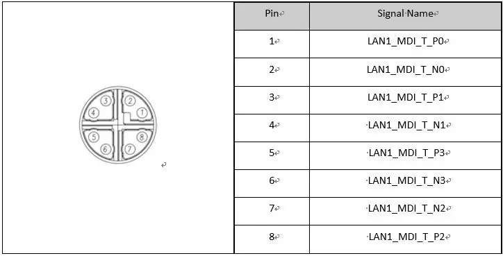
| Ethernet | 2 x X-coded M12 GbE ports with 2kV isolation | |
|
Expansion Slot | 2 x mPCIe Compliant to PCI Express® Mini Card Electromechanical Specification Revision 1.2 supporting USB2.0 & PCIe x1 Note : We will populate zero ohm links to pins 28 and 48 as standard on mini PCIe (USB2.0/PCIe)) which can be depopulated if required.
2 x mPCIe support USB 3.0 Note : We will populate dip switches to switch system reset and NC on pins 22 and 48. and we will populate dip switches to switch 1.5V and NC on pins 28, according to LM960 and MC7455 Pin definition
2 x M.2 3042 Key B USB 3.0 | |
| Indicator LED | 1 x Standby, 1 x Storage, 1 x WDT, 8 x User defined | |
| Button | Front panel Power Button and Reset button | |
| Mounting | Wall-mount kit | |
| GND | M6 threaded stud for protective grounding | |
| MTBF & Reliability | MTBF | 15.1 Years |
| Power | Power input | +24/36/72/110VDC with M12 4-pin S code connector |
| (16.8V to 137.5V, EN50155 compliant) -154V reverse polarity protection 161V(+-2%) over-voltage protection A TVS diode is fitted between the plus and minus power inputs, there are no voltage clamping devices between these inputs and the chassis. A standard 1000VAC voltage withstand test with shorted plus – minus is supported. | ||
|
Ignition input | “Compare Vin_positive with Ignition, IF Ignition >70% of Vin_positive = System ON, IF Ignition <20% of Vin_positive = System OFF BIOS will provide Power off delay time option: 5,10,15 minutes. Input protected to same level as power input | |
| Compliance | Compliant to Interruptions of voltage supply according EN50155 SEC. 5.1.1.4 Class S2 (10ms) by capacitance | |
| Power Consumption | <80W with 100% CPU loading | |
|
Mechanical | Material | Extruded aluminum heatsink with chromate conversion coating cf. MIL-DTL- 81706 B (conductive surface) |
| Ingress Protection | IP41 | |
| Dimensions | 355 mm (W) x 204.5 mm (D) x 66mm(H) | |
| Net Weight | <7kg | |
|
Software | BIOS | AMI |
| Watchdog | 1~255 sec. system reset | |
| Operating System | Ubuntu 16.04.6, 64 bit Debian 10.0.0, 64 bit | |
|
Environment & Certification | Operating Temperature | -40°C ~ 70°C (EN50155 TX Class,+85C for 10mins) |
| Storage Temperature | -40°C ~ +85°C | |
| Humidity operating | 10% to 95% relative humidity (non-condensing) | |
| Humidity storage | 5% to 95% relative humidity (non-condensing) | |
|
EMC | EN50155:2017, EN50121-3-2:2016 EN50124-1:2006, EN61000-4-2:2009 EN61000-4-3:2006 + A1:2008 + A2:2010 EN61000-4-4:2012, EN61000-4-5:2014 EN61000-4-6:2014, EN55022:2006 + A2:2010 |
|
Environmental | EN50155:2017, EN61373:2010 EN60068-2-1:2007, EN60068-2-2:2007 EN60068-2-27:2009, EN60068-2-30:2005, EN60068-2-64:2008 RoHS 2.0 & REACH | |
|
Safety | Fire Protection | Compliant to EN45545-2:2013+A1:2015 (HL 1-3) |
| Rolling stock | BS EN 50155:2017 | |
|
Protection of system | Electrical isolation 2200VDC galvanic isolation of power input to output Power supply interface is floating (1500VDC) | |
|
Others |
Others | No CMOS battery – RTC will not maintain date time information Torx screws for modem access area Pigtail kits to support standard fitment a. Pigtail Accessory kit 1 : 12x MHF4 Pigtail b. Pigtail Accessory kit 2 : 4x MHF4 Pigtail and 4x U.FL Pigtail Mounting bracket to customer dimensions – detailed in chassis top view drawing NDL 8192 range of MAC addresses to be programmed into NICs – NDL and ADLINK to define suitable MAC address format for receipt into production facility. Front Panel to include Customer logo in white PCBs conformal coated – type HumiSeal 1B73 Coating (AR) Acrylic. |
System Block Diagram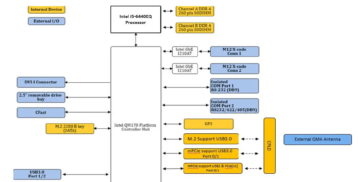
Mechanical Drawing reference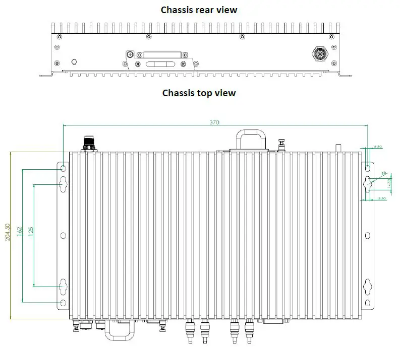
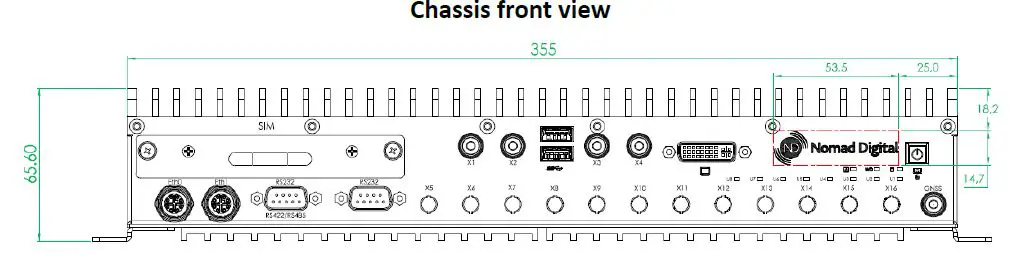
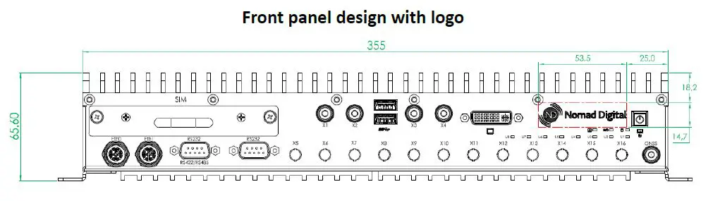
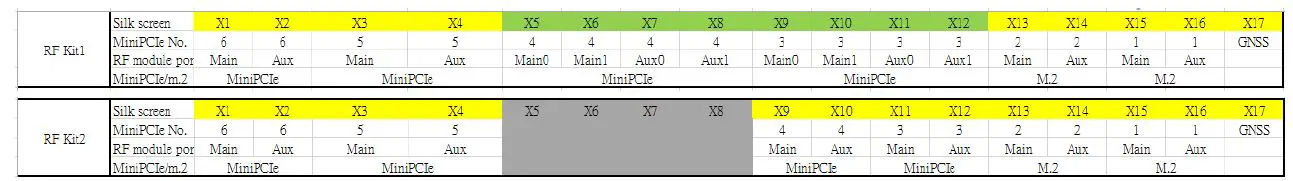
Front panel labelling
Internal drawings and Warning statement
Drawing of M.2/mPCIe area and PCB designations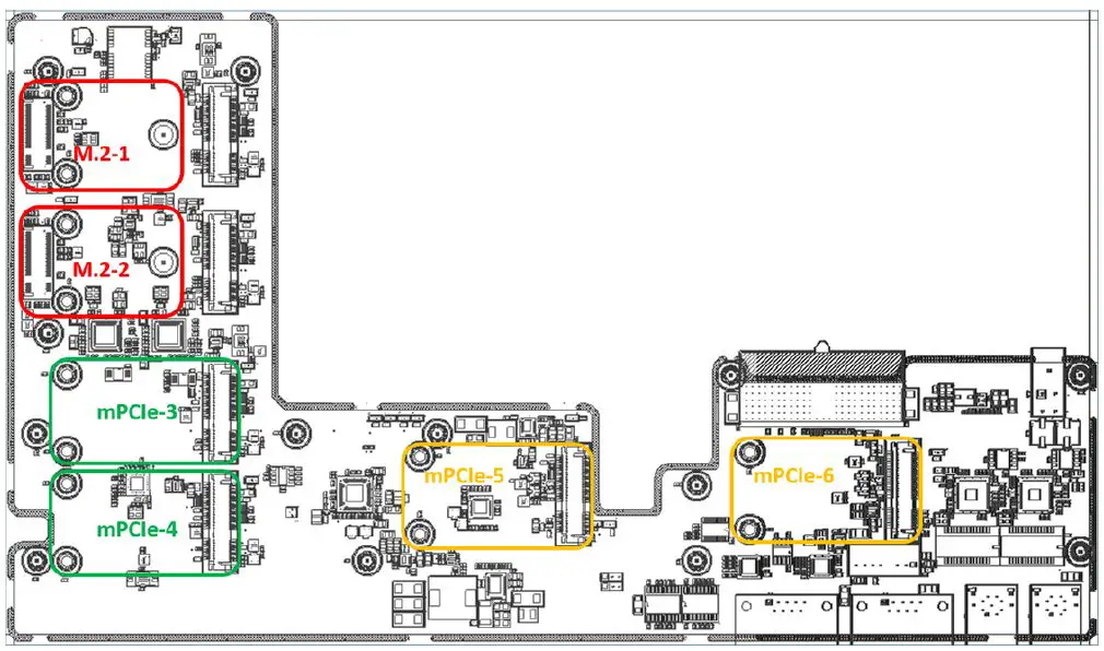
Acc. to FCC rule 15.21
The users manual or instruction manual for an intentional or unintentional radiator shall caution the user that changes or modifications not expressly approved by the party responsible for compliance could void the user’s authority to operate the equipment. In cases where the manual is provided only in a form other than paper, such as on a computer disk or over tile Internet tile information required by this section may be included in the manual in that alternative form provided tile user can reasonably be expected ed to have the capability to access information in that form.
Suggested Pigtail routing
| Optional Pigtail Accessory kit 1 P/N : 91-95261-000E | 12x MHF4 Pigtail |
| Optional Pigtail Accessory kit 2 P/N : 91-95261-010E | 4x MHF4 Pigtail and 4x U.FL Pigtail |
Design Details
Power ignition control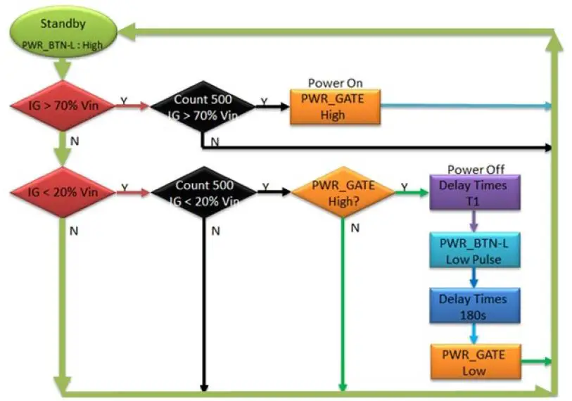
Note: BIOS will provide Power off delay time option: 5,10,15 minutes.
Connector details and Pin out
External Connectors
Main power and Ignition input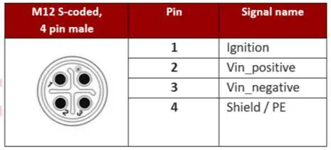
M12 LAN Port port (X-coded) from external cable side
USB 3.0 Ports
USB 3.0 Type A connection – compatible with Super-Speed, Hi-Speed, full-speed and low-speed USB devices, with support for multiple boot devices, including USB flash, USB external HDD, and USB CD-ROM drives and boot priority and boot device configured in BIOS.
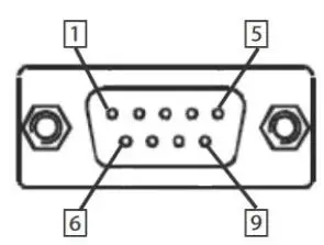
| Pin | RS-232 | RS-422 | RS-485 |
| 1 | DCD# | TXD422- | 485DATA- |
| 2 | RXD | TXD422+ | 485DATA+ |
| 3 | TXD | RXD422+ | N/S |
| 4 | DTR# | RXD422- | N/S |
| 5 | GND | N/S | N/S |
| 6 | DSR# | N/S | N/S |
| 7 | RTS# | N/S | N/S |
| 8 | CTS# | N/S | N/S |
| 9 | RI# | N/S | N/S |
Additional data
Battery – not installed due to long term reliability concerns, system will lose date and time information when powered off, but will not show any error messages relating to a low or missing CMOS battery.
USB Port Power – The USB ports provide power to support external USB devices, these are protected against overload with a self-recovering poly fuse.
DVI Port Power – The DVI port provides power output and this is protected against overload with a self-recovering poly fuse.
Important Safety Instructions
For user safety, please read and follow all instructions, WARNINGS, CAUTIONS, and
NOTES marked in this manual and on the associated equipment before handling/operating the equipment.
- Read these safety instructions carefully.
- Keep this user’s manual for future reference.
- Read the specifications section of this manual for detailed information on the operating environment of this equipment.
- When installing/mounting or uninstalling/removing equipment:
- Turn off power and unplug any power cords/cables.
- To avoid electrical shock and/or damage to equipment:
- Keep equipment away from water or liquid sources;
- Keep equipment away from high heat or high humidity;
- Keep equipment properly ventilated (do not block or cover ventilation openings);
- Make sure to use recommended voltage and power source settings;
- Always install and operate equipment near an easily accessible electrical socket-outlet;
- Secure the power cord (do not place any object on/over the power cord);
- Only install/attach and operate equipment on stable surfaces and/or recommended mountings; and,
- If the equipment will not be used for long periods of time, turn off and unplug the equipment from its power source.
- Never attempt to fix the equipment. Equipment should only be serviced by qualified personnel.
- A Lithium-type battery may be provided for uninterrupted, backup or emergency power.
- Equipment must be serviced by authorized technicians when:
- The power cord or plug is damaged;
- Liquid has penetrated the equipment;
- It has been exposed to high humidity/moisture;
- It is not functioning or does not function according to the user’s manual;
- It has been dropped and/or damaged; and/or,
- It has an obvious sign of breakage.


