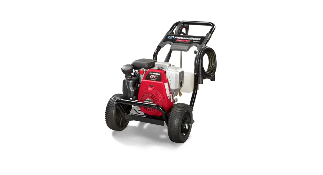
![]() 020649-00 3100 PSI Gas-Cold Water Pressure Washer with Honda Engine
020649-00 3100 PSI Gas-Cold Water Pressure Washer with Honda Engine
Owner’s Manual
Main Unit (80017859)
Note: Unless noted otherwise, use the standard torque specifications
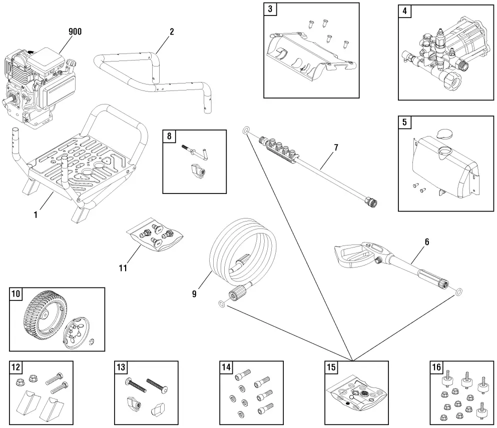
| REF NO | PART NO | QTY | DESCRIPTION |
| 1 | 313788GS | BASE | |
| 2 | 201499ZGS | HANDLE | |
| 3 | 709519 | BILLBOARD | |
| — | B1797GS | CLIP | |
| 4 | 709521 | PUMP | |
| 5 | 205369GS | TANK-CHEMICAL | |
| — | B3222EGS | CAP-CHEMICAL TANK | |
| — | B1797GS | CLIPS | |
| — | 310333GS | KIT-VALVE | |
| 6 | 708807 | GUN | |
| 7 | 207796GS | EXTENSION-QC | |
| 8 | 194264GS | HOOK | |
| 9 | 708962 | HOSE | |
| 10 | 209891GS | KIT-WHEEL | |
| — | 209604GS | HUBCAP | |
| — | 704293 | E-RING | |
| 11 | 709520 | KIT-QC NOZZLES | |
| — | 198841GS | NOZZLE-QC BLACK | |
| — | 195983AAGS | NOZZLE-QC RED | |
| — | 195983TGS | NOZZLE-QC YELLOW | |
| — | 707480 | NOZZLE-QC WHITE | |
| 12 | 209884GS | MOUNT-VIBRATION | |
| 13 | B2203GS | KIT-HARDWARE HANDLE | |
| 14 | 192131GS | KIT-HARDWARE PUMP MOUNTING | |
| 15 | 705001 | KIT-O-RING | |
| 16 | 192134GS | KIT-VIBRATION MOUNT | |
| 900 | —– | ** ENGINE | |
| — | 319068GS | OIL -(Not Illustrated) | |
| — | 23139DGS | KEY -(Not Illustrated) | |
| — | 201314GS | AXLE -(Not Illustrated) | |
| — | 705076 | HOSE-CHEMICAL -(Not Illustrated) | |
| — | 705851 | DECAL-Warning Spark -(Not Illustrated) | |
| — | 707165 | TAG-WARNING -(Not Illustrated) | |
| — | 6039 | PUMP SAVER -(Optional Accessory) |
Footnotes:
** Contact Engine Manufacturer for parts and service.
Pump (80017740)
Note: Unless noted otherwise, use the standard torque specifications

| REF NO | PART NO | QTY | DESCRIPTION |
| 1 | 204087GS | 3 | SCREW |
| 44 | B2384GS | 1 | FILTER, Garden Hose |
| 46 | 204083GS | 1 | FITTING, Outlet |
| 64 | 208673GS | 1 | VALVE, Thermal Relief |
| A | 317897GS | 1 | * KIT, Check Valve |
| B | 706780 | 1 | * KIT-PLUG |
| C | 204084GS | 1 | * KIT, Water Seals |
| D | 317787GS | 1 | *KIT, Chemical Injector |
| E | 317788GS | 1 | *KIT, Easy Start |
| F | 709523 | 1 | KIT-O-RING |
| G | 200350GS | 1 | * KIT, Grub Screw & Washer |
| H | 706610 | 1 | * KIT, Unloader |
| J | 204085GS | 1 | * KIT, Water Inlet |
| — | 6039 | PUMP Saver -(Optional Accessory) | |
| — | 6059 | PERFECT MIX MULTI-PURPOSE WASH -(Optional Accessory) | |
| — | 6160 | Project Pro® PerfectMix Concrete, Brick, and Tile Cleaner -(Optional Accessory) | |
| — | 6159 | Project Pro® PerfectMix Multi-Purpose and Vehicle Cleaner -(Optional Accessory) |
Hardware Identification & Torque Specifications
| Torque Specification Chart FOR STANDARD METRIC MACHINE HARDWARE (Tolerance ± 20%) | ||||||||
| Property Class | ||||||||
| Size Of Hardware | in/lbs ft/lbs | Nm. | in/lbs ft/lbs | Nm. | in/lbs ft/lbs | Nm. | in/lbs ft/lbs | Nm. |
| M3 M4 M5 M6 M7 M8 M10 M12 M14 M16 M18 M20 M22 M24 M27 M30 M33 M36 M39 | 5.88 13.44 26.4 44.64 5.2 7.7 15 26 42 64 89 126 169 217 320 435 590 759 988 | .56 1.28 2.50 4.3 7.1 10.5 21 36 58 88 121 171 230 295 435 590 800 1030 1340 | 13.44 30.72 60.96 7.3 12.1 17.7 35 61 101 147 202 290 390 497 733 995 1349 1740 2249 | 1.28 2.90 5.75 9.9 16.5 24 48 83 132 200 275 390 530 375 995 1350 1830 2360 3050 | 19.2 43.44 5.97 10.3 16.9 25 50 86.2 136 210 287 405 559 708 1032 1401 1902 2441 3163 | 1.80 4.10 8.10 14 23 34 67 117 185 285 390 550 745 960 1400 1900 2580 3310 4290 | 22.92 52.56 7.15 12.1 19.9 29 59 103 162 250 346 486 656 840 1239 1681 2278 3798 2935 | 2.15 4.95 16.5 9.7 27 40 81 140 220 340 470 660 890 1140 1680 2280 3090 3980 5150 |
The guides and ruler furnished below are designed to help you select the appropriate hardware.
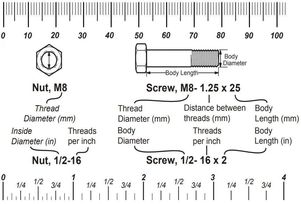
Standard Hardware Sizing
When a washer or nut is identified as 1/2” (M8), this is the Nominal size, meaning the inside diameter is 1/2 inch (8mm metric thread diameter); if a second number is present
it represents the threads per inch (distance between threads).
When the bolt or capscrew is identified as 1/2 – 16 x 2” (M8 – 1.25 x 50), this means the Nominal size, or body diameter is 1/2 inch (8mm metric thread diameter), the second number,16, represents the threads per inch, (distance between threads). The final number is the body length of the bolt or screw, 2 inches (50mm).
| Torque Specification Chart FOR STANDARD MACHINE HARDWARE (Tolerance ± 20%) | ||||||
| Hardware Grade | ||||||
| Size Of Hardware | in/lbs ft/lbs | Nm. | in/lbs ft/lbs | Nm. | in/lbs ft/lbs | Nm. |
| 8-32 8-36 10-24 10-32 1/4-20 1/4-28 5/16-18 5/16-24 3/8-16 3/8-24 7/16-14 7/16-20 1/2-13 1/2-20 9/16-12 9/16-18 5/8-11 5/8-18 3/4-10 3/4-16 7/8-9 7/8-14 1-8 1-12 | 19 20 27 31 66 76 11 12 20 23 30 35 50 55 65 75 90 100 160 180 140 155 220 240 | 2.1 2.3 3.1 3.5 7.6 8.6 15.0 16.3 27.2 31.3 40.8 47.6 68.0 74.8 88.4 102.0 122.4 136 217.6 244.8 190.4 210.8 299.2 326.4 | 30 31 43 49 8 10 17 19 30 35 50 55 75 90 110 120 150 180 260 300 400 440 580 640 | 3.4 3.5 4.9 5.5 10.9 13.6 23.1 25.8 40.8 47.6 68.0 74.8 102.0 122.4 149.6 163.2 204.0 244.8 353.6 408.0 544.0 598.4 788.8 870.4 | 41 43 60 68 12 14 25 29 45 50 70 80 110 120 150 170 220 240 386 420 600 660 900 1,000 | 4.6 4.9 6.8 7.7 16.3 19.0 34.0 34.0 61.2 68.0 95.2 108.8 149.6 163.2 204.0 231.2 299.2 326.4 525.0 571.2 816.0 897.6 1,244.0 1,360.0 |
NOTES
- These torque values are to be used for all hardware excluding locknuts, self-tapping screws, thread forming screws, sheet metal screws, and socket head setscrews.
- Recommended seating torque values for locknuts:
a. for prevailing torque locknuts – use 65% of grade 5 torques.
b. for flange whiz lock nuts and screws – use 135% of grade 5 torques. - Unless otherwise noted on assembly drawings, all torque values must meet this specification.
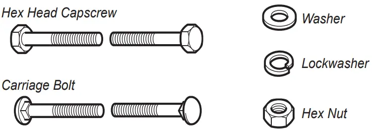
Common Hardware Types
Wrench & Fastener Size Guide
 | ||||
| 1/4” Bolt or Nut Wrench—7/16” | 5/16” Bolt or Nut Wrench—1/2” | 3/8” Bolt or Nut Wrench—9/16” | 7/16” Bolt or Nut Wrench (Bolt)—5/8” Wrench (Nut)—11/16” | 1/2” Bolt or Nut Wrench—3/4” |
| M6 Bolt or Nut Wrench—10mm | M8 Bolt or Nut Wrench—13mm | M10 Bolt or Nut Wrench—17mm | M12 Bolt or Nut Wrench—19mm | M14 Bolt or Nut Wrench—22 mm |
![]() Copyright © Briggs & Stratton. All Rights Reserved
Copyright © Briggs & Stratton. All Rights Reserved
01-Jun-2021


