Danfoss FC 360 VLT AutomationDrive Frequency Converter User Guide
Introduction
This operating guide provides necessary information for qualified personnel to install and commission the AC drive. Read and follow the instructions to use the drive safely and professionally.
Do not dispose of equipment containing electrical components together with domestic waste. Collect it separately in accordance with local and currently valid legislation.
Safety
Pay particular attention to the safety instructions and general warnings to avoid the risk of death, serious injury, and equipment or property damage.
![]() WARNING
WARNING ![]()
HIGH VOLTAGE
AC drives contain high voltage when connected to AC mains input, DC supply, or load sharing.
UNINTENDED START
The motor may start from control panel, I/O inputs, or fieldbus at any time, when the drive is connected to the AC mains, DC supply, or load sharing.
DISCHARGE TIME
The drive contains DC-link capacitors, which can remain charged even when the drive is not powered. High voltage can be present even when the warning indicator lights are off.
- Stop the motor, and disconnect AC mains, permanent magnet type motors, and remove DC-link supplies, including battery backups, UPS, and DC-link connections to other drives.
- Wait for the capacitors to discharge fully and measure it before performing any service or repair work.
- The minimum waiting time is 4 minutes for 0.37–7.5 kW (0.5–10 hp) drives and 15 minutes for 11–90 kW (15–125 hp) drives.
LEAKAGE CURRENT
Leakage currents of the drive exceed 3.5 mA. Make sure that the minimum size of the ground conductor complies with the local safety regulations for high-touch-current equipment.
Installation
Mechanical Dimensions
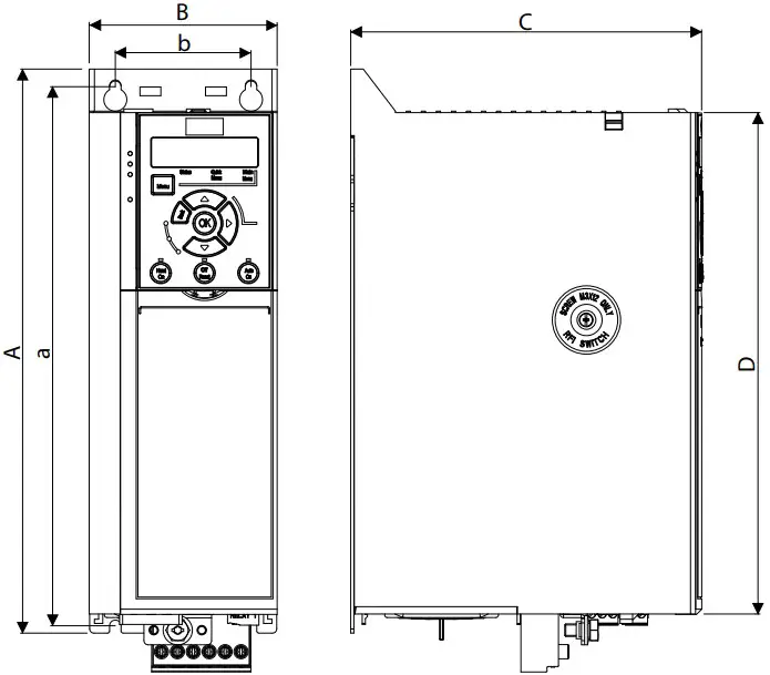
Illustration 1: Mechanical Dimensions, Enclosure Sizes J1–J7
| Enclosure size 380–480 V | J1 | J2 | J3 | J4 | J5 | J6 | J7 |
| Power size [kW (hp)] | 0.37–2.2(0.5–3) | 3.0–5.5(4.0–7.5) | 7.5(10) | 11–15(15–20) | 18.5–22(25–30) | 30–45(40–60) | 55–90(75–125) |
| Height A | 210 (8.3) | 272.5 (10.7) | 272.5 (10.7) | 317.5 (12.5) | 410 (16.1) | 515 (20.3) | 550 (21.7) |
| Width B | 75 (3.0) | 90 (3.5) | 115 (4.5) | 133 (5.2) | 150 (5.9) | 233 (9.2) | 308 (12.1) |
| Depth C | 168 (6.6) | 168 (6.6) | 168 (6.6) | 245 (9.6) | 245 (9.6) | 241 (9.5) | 323 (12.7) |
| Depth C(1) | 173 (6.8) | 173 (6.8) | 173 (6.8) | 250 (9.8) | 250 (9.8) | 241 (9.5) | 323 (12.7) |
| D | 180 (7.1) | 240 (9.4) | 240 (9.4) | 270 (10.6) | 364.7 (14.4) | 452 (17.8) | 484.5 (19.0) |
| Mounting holes | |||||||
| a | 198 (7.8) | 260 (10.2) | 260 (10.2) | 297.5 (11.5) | 390 (15.4) | 495 (19.5) | 521 (20.5) |
| b | 60 (2.4) | 70 (2.8) | 90 (3.5) | 105 (4.1) | 120 (4.7) | 200 (7.9) | 270 (10.6) |
| Mounting screw | M4 | M5 | M5 | M6 | M6 | M8 | M8 |
Removing the Front Cover
Procedure:
Remove the front cover with a screwdriver.
Illustration 2: Removing the Front Cover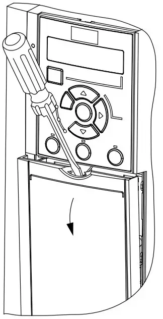
Illustration 5: Mains, Motor, and Ground Connections (Enclosure Sizes J1–J5)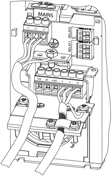
Connecting to Mains, Motor, Control Terminals, and Relays
Illustration 3: Control Terminals and Relays Connections (Enclosure Sizes J1–J5)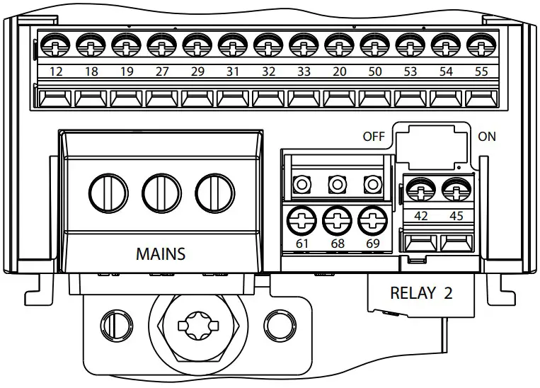
Illustration 4: Control Terminals and Relays Connections (Enclosure Sizes J6–J7)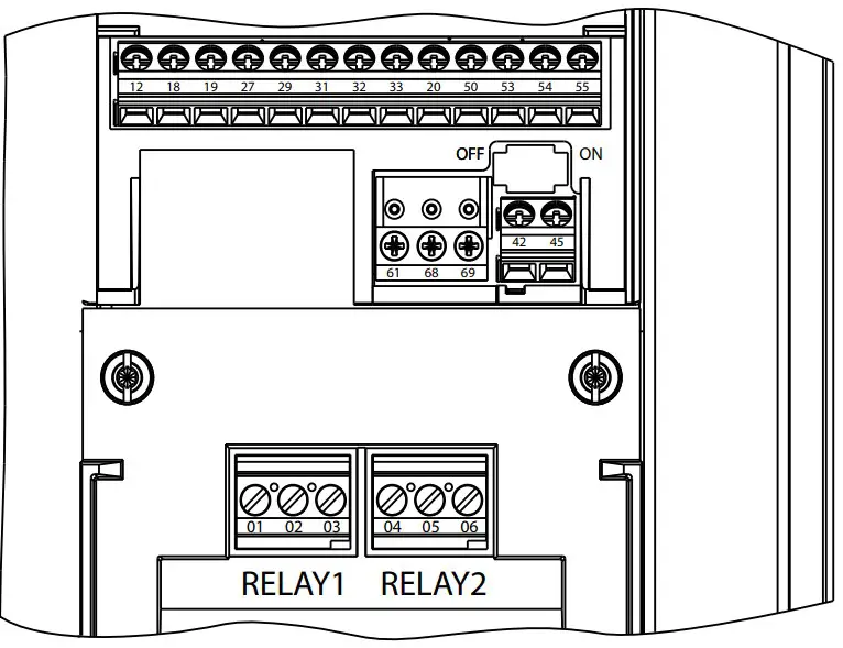
Illustration 6: Mains, Motor, and Ground Connections (Enclosure Sizes J6–J7)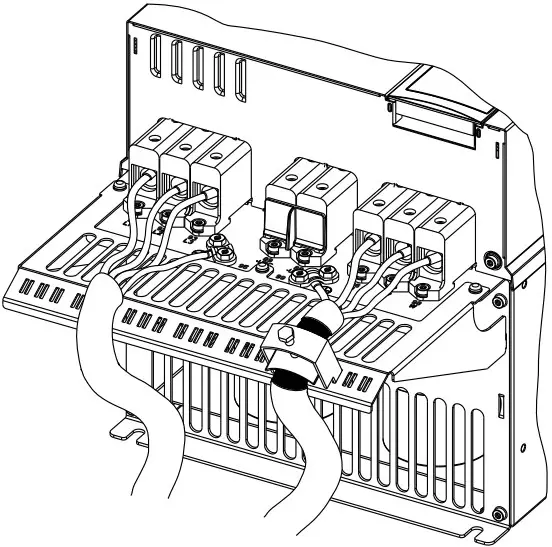
Control Terminals
Illustration 7: Control Terminals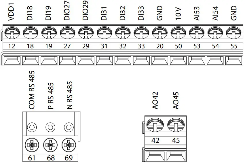
Specifcations
Table 2: Electrical Data for High Overload, Mains Supply 3×380–480 V AC, Enclosure Size J1–J3
| Drive | HK37 | HK55 | HK75 | H1K1 | H1K5 | H2K2 | H3K0 | H4K0 | H5K5 | H7K5 | ||||||||||
| Enclosure size | J1 | J1 | J1 | J1 | J1 | J1 | J2 | J2 | J2 | J3 | ||||||||||
| High overload=150–160 % current during 60 s | ||||||||||||||||||||
| Typical shaft output [kW] | 0.37 | 0.55 | 0.75 | 1.1 | 1.5 | 2.2 | 3 | 4 | 5.5 | 7.5 | ||||||||||
| Typical shaft output [hp] | 0.5 | 0.75 | 1 | 1.5 | 2 | 3 | 4 | 5.5 | 7.5 | 10 | ||||||||||
| Output current (3-phase) | ||||||||||||||||||||
| Continuous (3×380–440 V) [A] | 1.2 | 1.7 | 2.2 | 3 | 3.7 | 5.3 | 7.2 | 9 | 12 | 15.5 | ||||||||||
| Continuous (3×441–480 V) [A] | 1.1 | 1.6 | 2.1 | 2.8 | 3.4 | 4.8 | 6.3 | 8.2 | 11 | 14 | ||||||||||
| Intermittent (60 s overload) [A] | 1.9 | 2.7 | 3.5 | 4.8 | 5.9 | 8.5 | 11.5 | 14.4 | 19.2 | 24.8 | ||||||||||
| Continuous kVA (400 V AC) [kVA] | 0.84 | 1.18 | 1.53 | 2.08 | 2.57 | 3.68 | 4.99 | 6.24 | 8.32 | 10.74 | ||||||||||
| Continuous kVA (480 V AC) [kVA] | 0.9 | 1.3 | 1.7 | 2.5 | 2.8 | 4.0 | 5.2 | 6.8 | 9.1 | 11.6 | ||||||||||
| Enclosure size | J1 | J1 | J1 | J1 | J1 | J1 | J2 | J2 | J2 | J3 | ||||||||||
| Maximum input current | ||||||||||||||||||||
| Continuous (3×380–440 V) [A] | 1.2 | 1.6 | 2.1 | 2.6 | 3.5 | 4.7 | 6.3 | 8.3 | 11.2 | 15.1 | ||||||||||
| Continuous (3×441–480 V) [A] | 1.0 | 1.2 | 1.8 | 2.0 | 2.9 | 3.9 | 4.3 | 6.8 | 9.4 | 12.6 | ||||||||||
| Intermittent (60 s overload) | 1.9 | 2.6 | 3.4 | 4.2 | 5.6 | 7.5 | 10.1 | 13.3 | 17.9 | 24.2 | ||||||||||
| Maximum cable size (mains, motor, brake, and load sharing) [mm2 (AWG)] | 4 (12) | |||||||||||||||||||
| Estimated power loss at rated maximum load [W] | 20.88 | 25.16 | 30.01 | 40.01 | 52.91 | 73.97 | 94.81 | 115.5 | 157.54 | 192.83 | ||||||||||
| Weight [kg (lb)](Enclosure protection rating IP20) | 2.3(5.1) | 2.3(5.1) | 2.3(5.1) | 2.3(5.1) | 2.3(5.1) | 2.5(5.5) | 3.6(7.9) | 3.6(7.9) | 3.6(7.9) | 4.1(9.0) | ||||||||||
| Efficiency [%] | 96.2 | 97.0 | 97.2 | 97.4 | 97.4 | 97.6 | 97.5 | 97.6 | 97.7 | 98.0 | ||||||||||
Table 3: Electrical Data for High Overload, Mains Supply 3×380–480 V AC, Enclosure Size J4–J7
| Drive | H11K | H15K | H18K | H22K | H30K | H37K | H45K | H55K | H75K |
| Enclosure size | J4 | J4 | J5 | J5 | J6 | J6 | J6 | J7 | J7 |
| High overload=150–160% current during 60 s | |||||||||
| Typical shaft output [kW] | 11 | 15 | 18.5 | 22 | 30 | 37 | 45 | 55 | 75 |
| Typical shaft output [hp] | 15 | 20 | 25 | 30 | 40 | 50 | 60 | 75 | 100 |
| Output current (3-phase) | |||||||||
| Continuous (3×380–440 V) [A] | 23 | 31 | 37 | 42.5 | 61 | 73 | 90 | 106 | 147 |
| Continuous (3×441–480 V) [A] | 21 | 27 | 34 | 40 | 52 | 65 | 77 | 96 | 124 |
| Intermittent (60 s overload) [A] | 34.5 | 46.5 | 55.5 | 63.8 | 91.5 | 109.5 | 135 | 159 | 220.5 |
| Continuous kVA (400 V AC) [kVA] | 15.94 | 21.48 | 25.64 | 29.45 | 42.3 | 50.6 | 62.4 | 73.4 | 101.8 |
| Continuous kVA (480 V AC) [kVA] | 17.5 | 22.4 | 28.3 | 33.3 | 43.2 | 54.0 | 64.0 | 79.8 | 103.1 |
| Maximum input current | |||||||||
| Continuous (3×380–440 V) [A] | 22.1 | 29.9 | 35.2 | 41.5 | 57 | 70.3 | 84.2 | 102.9 | 140.3 |
| Continuous (3×441–480 V) [A] | 18.4 | 24.7 | 29.3 | 34.6 | 49.3 | 60.8 | 72.7 | 88.8 | 121.1 |
| Intermittent (60 s overload) | 33.2 | 44.9 | 52.8 | 62.3 | 85.5 | 105.5 | 126.3 | 154.4 | 210.5 |
| Maximum cable size (mains, motor, brake, and load sharing) [mm2 (AWG)] | 16 (6) | 50 (1/0) | 95 (3/0) | ||||||
| Estimated power loss at rated maximum load [W] | 289.53 | 393.36 | 402.83 | 467.52 | 630 | 848 | 1175 | 1250 | 1507 |
| Weight [kg (lb)](Enclosure protection rating IP20) | 9.4(20.7) | 9.5(20.9) | 12.3(27.1) | 12.5(27.6) | 22.4(49.4) | 22.5(49.6) | 22.6(49.8) | 37.3(82.2) | 38.7(85.3) |
| Efficiency [%] | 97.8 | 97.8 | 98.1 | 97.9 | 98.1 | 98.0 | 97.7 | 98.0 | 98.2 |
Table 4: Electrical Data for Normal Overload, Mains Supply 3×380–480 V AC, Enclosure Size J4–J7
| Drive | Q11K | Q15K | Q18K | Q22K | Q30K | Q37K | Q45K | Q55K | Q75K | Q90K |
| Enclosure size | J4 | J4 | J5 | J5 | J6 | J6 | J6 | J7 | J7 | J7 |
Normal overload=110% current during 60 s | ||||||||||
| Typical shaft output [kW] | 11 | 15 | 18.5 | 22 | 30 | 37 | 45 | 55 | 75 | 90 |
| Typical shaft output [hp] | 15 | 20 | 25 | 30 | 40 | 50 | 60 | 75 | 100 | 125 |
| Output current (3-phase) | ||||||||||
| Continuous (3×380–440 V) [A] | 23 | 31 | 37 | 42.5 | 61 | 73 | 90 | 106 | 147 | 177 |
| Continuous (3×441–480 V) [A] | 21 | 27 | 34 | 40 | 52 | 65 | 77 | 96 | 124 | 160 |
| Intermittent (60 s overload) [A] | 25.3 | 34.1 | 40.7 | 46.8 | 67.1 | 80.3 | 99 | 116.6 | 161.7 | 194.7 |
| Continuous kVA (400 V AC) [kVA] | 15.94 | 21.48 | 25.64 | 29.45 | 42.3 | 50.6 | 62.4 | 73.4 | 101.8 | 122.6 |
| Continuous kVA (480 V AC) [kVA] | 17.5 | 22.4 | 28.3 | 33.3 | 43.2 | 54.0 | 64.0 | 79.8 | 103.1 | 133 |
Maximum input current | ||||||||||
| Continuous (3×380–440 V) [A] | 22.1 | 29.9 | 35.2 | 41.5 | 57 | 70.3 | 84.2 | 102.9 | 140.3 | 165.6 |
| Continuous (3×441–480 V) [A] | 18.4 | 24.7 | 29.3 | 34.6 | 49.3 | 60.8 | 72.7 | 88.8 | 121.1 | 142.7 |
| Intermittent (60 s overload) | 24.3 | 32.9 | 38.7 | 45.7 | 62.7 | 77.3 | 92.6 | 113.2 | 154.3 | 182.2 |
| Maximum cable size (mains, motor, brake, and load sharing) [mm2 (AWG)] | 16 (6) | 50 (1/0) | 95 (3/0) | 120 (4/0) | ||||||
| Estimated power loss at rated maximum load [W] | 289.53 | 393.36 | 402.83 | 467.52 | 630 | 848 | 1175 | 1250 | 1507 | 1781 |
| Weight [kg (lb)] (Enclosure protection rating IP20) | 9.4 (20.7) | 9.5 (20.9) | 12.3 (27.1) | 12.5 (27.6) | 22.4 (49.4) | 22.5 (49.6) | 22.6 (49.8) | 37.3 (82.2) | 38.7 (85.3) | 40.7 (89.7) |
| Efficiency [%] | 97.8 | 97.8 | 98.1 | 97.9 | 98.1 | 98.0 | 97.7 | 98.0 | 98.2 | 98.3 |
Table 4: Electrical Data for Normal Overload, Mains Supply 3×380–480 V AC, Enclosure Size J4–J7
| Drive | Q11K | Q15K | Q18K | Q22K | Q30K | Q37K | Q45K | Q55K | Q75K | Q90K |
| Enclosure size | J4 | J4 | J5 | J5 | J6 | J6 | J6 | J7 | J7 | J7 |
| Normal overload=110% current during 60 s | ||||||||||
| Typical shaft output [kW] | 11 | 15 | 18.5 | 22 | 30 | 37 | 45 | 55 | 75 | 90 |
| Typical shaft output [hp] | 15 | 20 | 25 | 30 | 40 | 50 | 60 | 75 | 100 | 125 |
| Output current (3-phase) | ||||||||||
| Continuous (3×380–440 V) [A] | 23 | 31 | 37 | 42.5 | 61 | 73 | 90 | 106 | 147 | 177 |
| Continuous (3×441–480 V) [A] | 21 | 27 | 34 | 40 | 52 | 65 | 77 | 96 | 124 | 160 |
| Intermittent (60 s overload) [A] | 25.3 | 34.1 | 40.7 | 46.8 | 67.1 | 80.3 | 99 | 116.6 | 161.7 | 194.7 |
| Continuous kVA (400 V AC) [kVA] | 15.94 | 21.48 | 25.64 | 29.45 | 42.3 | 50.6 | 62.4 | 73.4 | 101.8 | 122.6 |
| Continuous kVA (480 V AC) [kVA] | 17.5 | 22.4 | 28.3 | 33.3 | 43.2 | 54.0 | 64.0 | 79.8 | 103.1 | 133 |
| Maximum input current | ||||||||||
| Continuous (3×380–440 V) [A] | 22.1 | 29.9 | 35.2 | 41.5 | 57 | 70.3 | 84.2 | 102.9 | 140.3 | 165.6 |
| Continuous (3×441–480 V) [A] | 18.4 | 24.7 | 29.3 | 34.6 | 49.3 | 60.8 | 72.7 | 88.8 | 121.1 | 142.7 |
| Intermittent (60 s overload) | 24.3 | 32.9 | 38.7 | 45.7 | 62.7 | 77.3 | 92.6 | 113.2 | 154.3 | 182.2 |
| Maximum cable size (mains, motor, brake, and load sharing) [mm2 (AWG)] | 16 (6) | 50 (1/0) | 95 (3/0) | 120 (4/0) | ||||||
| Estimated power loss at rated maximum load [W] | 289.53 | 393.36 | 402.83 | 467.52 | 630 | 848 | 1175 | 1250 | 1507 | 1781 |
| Weight [kg (lb)](Enclosure protection rating IP20) | 9.4(20.7) | 9.5(20.9) | 12.3(27.1) | 12.5(27.6) | 22.4(49.4) | 22.5(49.6) | 22.6(49.8) | 37.3(82.2) | 38.7(85.3) | 40.7(89.7) |
| Efficiency [%] | 97.8 | 97.8 | 98.1 | 97.9 | 98.1 | 98.0 | 97.7 | 98.0 | 98.2 | 98.3 |
Ambient Conditions
| J1–J7 enclosure size | IP20 |
| Vibration test | 1.0 g |
| Relative humidty | 5%–95% (IEC 721-3-3; Class 3K3 (non-condensing) during operation) |
| Aggressive environment (IEC 60068-2-43) H2S test | Class Kd |
| Test method according to IEC 60068-2-43 | H2S (10 days) |
Ambient temperature (at 60 AVM switching mode)
| Maximum 55 °C (131 °F)Maximum 45 °C (113 °F)1) |
| Minimum ambient temperature during full-scale operation | -15 °C (5 °F) |
| Minimum ambient temperature at reduced performance | -20 °C (-4 °F) |
| Temperature during storage/transport | -25 to +65/70 °C (-13 to +149/158 °F) |
| Maximum altitude above sea level without derating | 1000 m (3281 ft) |
| Maximum altitude above sea level with derating | 3000 m (9842 ft) |
Note: (1) P90K operates at 40 °C (104 °F).
Mounting Clearance
| Enclosure size | J1–J5 | J6–J7 |
| Clearance above and below the unit [mm (in)]) | 100 (3.94) | 200 (7.87) |
EMC Compatibility and Motor Cable Length
| EMC standard, Emission/Immunity | Category C3/EN/IEC 61800-3 | |
| Maximum motor cable length, shielded | 50 m (164 ft) | |
| Maximum motor cable length, unshielded | 0.37–22 kW (0.5–30 hp) | 75 m (246 ft) |
| 30–90 kW (40–125 hp) | 100 m (328 ft) | |
| Maximum cross-section to control terminals, flexible/rigid wire | 2.5 mm2/14 AWG | |
| Minimum cross-section to control terminals | 0.55 mm2/30 AWG | |
Programming
Local Control Panel (LCP)
Illustration 8: Local Control Panel (LCP 21 and LCP 23)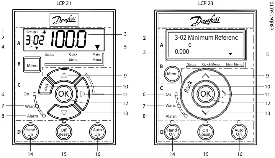
Functional Section A: Display
Table 5: Display Function
| Number | Function |
| 1 | The setup number shows the active setup and the edit setup.
|
| 2 |
|
| 3 | Parameter value. |
| 4 | Motor direction indicated by a small arrow pointing either clockwise or counterclockwise. For LCP 23, it only shows in status menu on the upper right corner of the screen. |
| 5 | The triangle indicates if the LCP is in Status, Quick Menu, or Main Menu. |
Functional Section B: Menu Key
Press [Menu] to select among Status, Quick Menu, or Main Menu.
Functional Section C: Indicator Lights (LEDs) and Navigation Keys
Table 6: Indicator Lights (LEDs)
Table 7: Navigation Keys
| Number | Key | Function |
| 9/13 | Up/Down | (1) Switches among parameter groups, parameters, and within parameters. (2) Increases or decre- ases parameter values. (3) Sets local reference. |
| 10 | [Back] | Moves to the previous step or layer in the navigation structure. |
| 11 | Right | Moves from left to right within the parameter value to change each digit individually. |
| 12 | [OK] | Selects a parameter and accepts changes to parameter settings. |
Functional Section D: Operation Keys and Indicator Lights (LEDs)
Table 8: Operation Keys and Indicator Lights (LEDs)
Number | Key | Function |
| 14 | [Hand On] | (1) Starts the drive in local control. (2) An external stop signal via control input or serial communi- cation overrides the local hand on command. |
| 15 | [Off/Reset] | (1) Stops the motor but does not remove power to the drive. (2) Resets the drive manually after a fault has been cleared. (3) In alarm mode, the alarm is reset when the alarm condition is removed. |
| 16 | [Auto On] | Puts the system in remote operational mode, in which the drive only respond to an external start command via control terminals or bus communication. |
NOTICE
[2] Coast inverse is the default option for parameter 5-12 Terminal 27 Digital Input. If there is no 24 V supply to terminal 27, [Hand On] does not start the motor. Connect terminal 12 to terminal 27Automatic Motor Adaptation (AMA)
- Via running AMA in VVC+ mode, the drive builds a mathematical model of the motor to optimize compati- bility between drive and motor, and thus enhances the motor control performance.
- Some motors may be unable to run the complete version of the test. In that case, select [2] Enable Reduced AMA in parameter 1-29 Automatic Motor Adaptation (AMA).
- For best results, run the following procedure on a cold motor.
Procedure:
- Set motor data in parameter group 1-** Load and Motor according to the motor nameplate.
- Connect terminal 27 to terminal 12 (24 V voltage) or choose [0] No operation in parameter 5-12 Terminal 27 Digital Input.
- Set [1] Enable Complete AMA or [2] Enable Reduced AMA for parameter 1-29 Automatic Motor Adaptation (AMA).
- Press the [Hand On] key, the test runs automatically and the main display indicates when it is completed
Troubleshooting
Table 9: Warning and Alarm Code List
| Number | Description | Warning | Alarm | Trip lock | Cause |
| 2 | Live zero error | X | X | – | Signal on terminal 53 or 54 is less than 50% of the values set in parameter 6-10 Terminal 53 Low Voltage, parameter 6-12 Terminal 53 Low Current, parameter 6-20 Terminal 54 Low Voltage, and parameter 6-22 Terminal 54 Low Current. |
| 3 | No motor | X | – | – | No motor has been connected to the output of the drive, or 1 motor phase is missing. |
| 4 | Mains phase loss(1) | X | X | X | Missing phase on the supply side, or the voltage imbalance is too high. Check the supply voltage. |
| 7 | DC overvoltage(1) | X | X | – | DC-link voltage exceeds the limit. |
| 8 | DC undervoltage(1) | X | X | – | DC-link voltage drops below the voltage warning low limit. |
| 9 | Inverter overloaded | X | X | – | More than 100% load for too long. |
| 10 | Motor ETR overtemp- erature | X | X | – | Motor is too hot due to more than 100% load for too long. |
| 11 | Motor thermistor overtemperature | X | X | – | Thermistor or thermistor connection is disconnected, or the motor is too hot. |
| 12 | Torque limit | X | X | – | Torque exceeds value set in either parameter 4-16 Torque Limit Motor Mode or parameter 4-17 Torque Limit Generator Mode. |
| 13 | Overcurrent | X | X | X | Inverter peak current limit is exceeded. For J1–J6 units, if this alarm occurs on power-up, check whether power cables are mistakenly connected to the motor terminals. |
| 14 | Ground fault | – | X | X | Discharge from output phases to ground. |
| 16 | Short circuit | – | X | X | Short circuit in motor or on motor terminals. For J7 units, if this alarm occurs on power-up, check whether power cables are mistakenly connected to the motor terminals. |
| 17 | Control word timeout | X | X | – | No communication to the drive. |
| 18 | Start failed | – | X | – | – |
| 25 | Brake resistor short- circuited | – | X | X | Brake resistor is short-circuited, thus the brake function is discon- nected. |
| 26 | Brake overload | X | X | – | The power transmitted to the brake resistor over the last 120 s exceeds the limit. Possible corrections: Decrease brake energy via lower speed or longer ramp time. |
| 27 | Brake IGBT/Brake chopper short-circuited | – | X | X | Brake transistor is short-circuited, thus brake function is disconn- ected. |
| 28 | Brake check | – | X | – | Brake resistor is not connected/working. |
| 30 | U phase loss | – | X | X | Motor phase U is missing. Check the phase. |
| 31 | V phase loss | – | X | X | Motor phase V is missing. Check the phase. |
| 32 | W phase loss | – | X | X | Motor phase W is missing. Check the phase. |
| 34 | Fieldbus fault | X | X | – | PROFIBUS communication issues have occurred. |
| 35 | Option fault | – | X | – | Fieldbus or option B detects internal faults. |
| 36 | Mains failure | X | X | – | This warning/alarm is only active if the supply voltage to the driveis lost and parameter 14-10 Mains Failure is NOT set to [0] No Fun- ction. |
| 38 | Internal fault | – | X | X | Contact the local supplier. |
| 40 | Overload T27 | X | – | – | Check the load connected to terminal 27 or remove short-circuit connection. |
| 41 | Overload T29 | X | – | – | Check the load connected to terminal 29 or remove short-circuit connection. |
| 46 | Gate drive voltage fault | – | X | X | – |
| 47 | 24 V supply low | X | X | X | 24 V DC may be overloaded. |
| 50 | AMA calibration | – | X | – | – |
| 51 | AMA check Unom and Inom | – | X | – | Wrong setting for motor voltage and/or motor current. |
| 52 | AMA low Inom | – | X | – | Motor current is too low. Check the settings. |
| 53 | AMA big motor | – | X | – | The power size of the motor is too large for the AMA to operate. |
| 54 | AMA small motor | – | X | – | The power size of the motor is too small for the AMA to operate. |
| 55 | AMA parameter range | – | X | – | The parameter values of the motor are outside of the acceptable range. AMA does not run. |
| 56 | AMA interrupt | – | X | – | The AMA is interrupted. |
| 57 | AMA timeout | – | X | – | – |
| 58 | AMA internal | – | X | – | Contact the local supplier. |
| 59 | Current limit | X | X | – | The drive is overloaded. |
| 60 | External Interlock | – | X | – | – |
| 61 | Encoder loss | X | X | – | – |
| 63 | Mechanical brake low | – | X | – | Actual motor current has not exceeded release brake currentwithin start delay time window. |
| 65 | Control card temp | X | X | X | The cutout temperature of the control card is 80 °C (176 °F). |
| 67 | Option module config- uration has changed | – | X | – | One or more options have either been added or removed since the last power-down. |
| 69 | Power card temp | X | X | X | – |
| 70 | Illegal FC config | – | X | X | – |
| 80 | Drive initialized todefault value | – | X | – | All parameter settings are initialized to default settings. |
| 87 | Auto DC brake | X | – | – | Occurs in IT mains when the drive coasts and the DC voltage is higher than 830 V. Energy on DC-link is consumed by the motor. This function can be enabled/disabled in parameter 0-07 Auto DC Braking. |
88 | Option detection | – | X | – | A change in the option layout is detected. Parameter 14-89 Option Detection is set to [0] Frozen configuration and the option layout has been changed.• To apply the change, enable option layout changes in parameter 14-89 Option Detection.• Alternatively, restore the correct option configuration. |
| 90 | Feedback monitor | X | X | – | A feedback fault is detected by option B. |
| 95 | Broken belt | X | X | – | – |
| 99 | Locked rotor | – | X | – | – |
| 101 | Flow/pressure inform-ation missing | – | X | X | – |
| 120 | Position control fault | – | X | – | – |
| 124 | Tension limit | – | X | – | – |
| 126 | Motor rotating | – | X | – | – |
| 127 | Back EMF too high(2) | X | – | – | Try to start PM motor which is rotating in an abnormal high speed. |
| 250 | New spare part | – | X | X | – |
| 251 | New type code | – | X | X | – |
Note:
- These faults may be caused by mains distortions. Installing a Sanford line filter may rectify this problem.
- For enclosure size J7, the warning can also be caused by high UDC voltage.
- An (X) marked in the above table indicates that the warning or alarm has occurred. A warning precedes an alarm
Accessories and Spare Parts
| Accessories and spare parts | Code number | Accessories and spare parts | Code number | ||
| (1) | VLT® encoder input MCB 102 | 132B0282 | (6) | Remote mounting kit for LCP with cable, 3 m | 132B0102 |
| (2) | VLT® resolver input MCB 103 | 132B0283 | (7) | LCP remote mounting cable, 3 m | 132B0132 |
| (3) | VLT® 24 V DC supply MCB 107 | 130B1208 | (8) | Standard control cassette | 132B0255 |
| (4) | VLT® graphical control panel LCP 23 | 132B0801 | (9) | Control cassette (with Profibus) | 132B0256 |
| (5) | VLT® numeric control panel LCP 21 | 132B0254 | (10) | Control cassette (with ProfiNet) | 132B0257 |
Technical Documentation
Scan the QR code to access more technical documents for the drive. Or, after scanning the QR code, click Global English on the website to select your local region’s website, search FC 360 to find the documents with your own languages.
Danfoss A/S: Danfoss can accept no responsibility for possible errors in catalogs, brochures, and other printed material.
Ulsnaes 1: Danfoss reserves the right to alter its products without notice. This also applies to products already on
DK-6300 Graasten: specifications already agreed. All trademarks in this material are property of the respective companies.
drives.danfoss.com: Danfoss and the Danfoss logotype are trademarks of Danfoss A/S. All rights reserved.