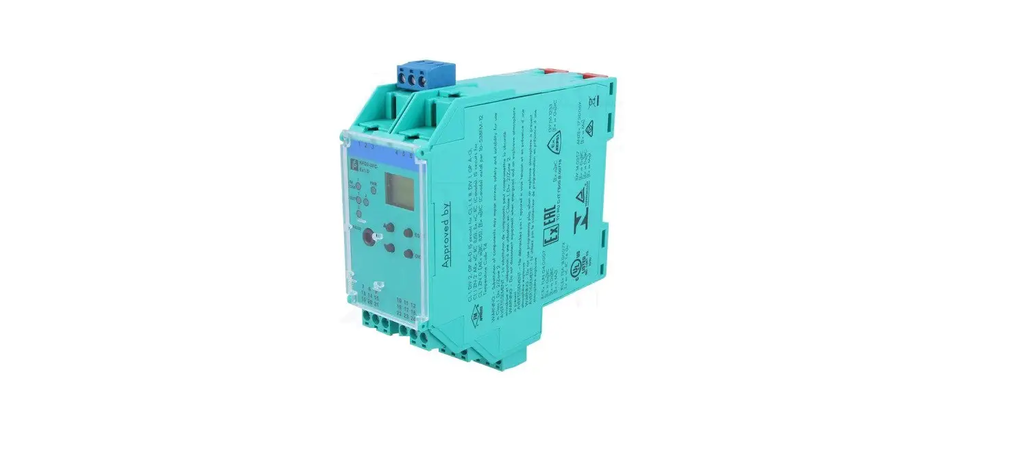
PEPPERL FUCHS KFD2-UFC-Ex1.D Frequency Converter with Trip Values
Frequency Converter with Trip Values
KFD2-UFC-Ex1.D
- 1-channel isolated barrier
- 24 V DC supply (Power Rail)
- Input for NAMUR sensors or dry contacts
- Input frequency 1 MHz … 5 kHz
- Current output 0/4 mA … 20 mA
- Relay contact and transistor output
- Start-up override
- Line fault detection (LFD)
- Up to SIL 2 acc. to IEC 61508/IEC 61511
Function
- This isolated barrier is used for intrinsic safety applications.
- The device is a universal frequency converter that changes a digital input signal into a proportional free adjustable 0/4 mA … 20 mA analog output signal and functions as a switch amplifier and a trip alarm.
- The functions of the switch outputs (2 relay outputs and 1 potential free transistor output) are easily adjustable [trip value display (min/max alarm), serially switched output, pulse divider output, error signal output].
- The device is easily configured by the use of keypad or with the PACTware configuration software.
- A fault is signalized by LEDs acc. to NAMUR NE44 and a separate collective error message output.
- For additional information, refer to the manual and www.pepperl-fuchs.com.
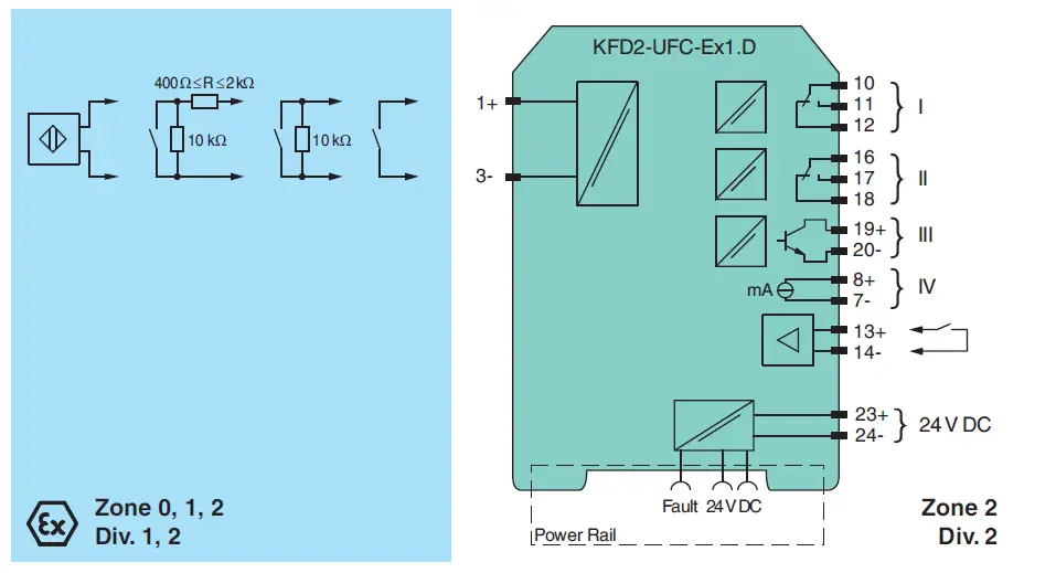
Connection
Technical Data
| General specifications | ||
| Signal type Digital Input | ||
| Functional safety related parameters | ||
| Safety Integrity Level (SIL) SIL 2 | ||
| Supply | ||
| Connection terminals 23+, 24- or power feed module/Power Rail | ||
| Rated voltage | Ur | 20 … 30 V DC |
| Rated current | Ir | approx. 100 mA |
| Power dissipation/power consumption | ≤ 2 W / 2.2 W | |
| Interface | ||
| Programming interface | programming socket | |
| Input | ||
| Connection side | field side | |
| Connection | Input I: intrinsically safe: terminals 1+, 3- Input II: non-intrinsically safe: terminals 13+, 14- | |
| Input I sensor acc. to EN 60947-5-6 (NAMUR) or mechanical contact | ||
| Pulse duration > 50 µs | ||
| Input frequency | 0.001 … 5000 Hz | |
| Line fault detection | breakage I ≤ 0.15 mA; short-circuit I > 6.5 mA | |
| Input II startup override: 1 … 1000 s, adjustable in steps of 1 s | ||
| Active/Passive I > 4 mA (for min. 100 ms) / I < 1.5 mA | ||
| Open circuit voltage/short-circuit current | 18 V / 5 mA | |
| Output | ||
| Connection side | control side | |
| Connection | output I: terminals 10, 11, 12 output II: terminals 16, 17, 18 outout III: terminasl 19+, 20- output IV: terminals 8+, 7- | |
| Output I, II signal, relay | ||
| Contact loading 253 V AC / 2 A / cos φ ≥ 0.7 ; 40 V DC / 2 A | ||
| Mechanical life | 5 x 10⁷ switching cycles | |
| Energized/De-energized delay | approx. 20 ms / approx. 20 ms | |
| Output III electronic output, passive | ||
| Contact loading 40 V DC | ||
| Signal level | 1-signal: (L+) – 2.5 V (50 mA, short-circuit/overload proof) 0-signal: switched off (off-state current ≤ 10 µA) | |
| Output IV | analog | |
| Current range 0 … 20 mA or 4 … 20 mA | ||
| Open loop voltage max. 24 V DC | ||
| Load | max. 650 Ω | |
| Fault signal | downscale I ≤ 3.6 mA , upscale ≥ 21.5 mA (acc. NAMUR NE43) | |
| Collective error message Power Rail | ||
| Transfer characteristics | ||
| Input I | ||
| Measurement range | 0.001 … 5000 Hz | |
| Resolution 0.1 % of the measurement value , ≥ 0.001 Hz | ||
| Accuracy 0.1 % of the measurement value , > 0.001 Hz | ||
| Measuring time | < 100 ms | |
| Influence of ambient temperature | 0.003 %/K (30 ppm) | |
| Output I, II | ||
| Response delay ≤ 200 ms | ||
| Output IV | ||
| Resolution | < 10 µA | |
| Accuracy < 20 µA | ||
| Influence of ambient temperature 0.005 %/K (50 ppm) | ||
| Galvanic isolation | ||
| Input I/other circuits reinforced insulation according to IEC/EN 61010-1, rated insulation voltage 300 Veff | ||
| Output I, II/other circuits | reinforced insulation according to IEC/EN 61010-1, rated insulation voltage 300 Veff | |
| Mutual output I, II, III | reinforced insulation according to IEC/EN 61010-1, rated insulation voltage 300 Veff | |
| Output III/power supply and collective error basic insulation according to IEC/EN 61010-1, rated insulation voltage 50 Veff | ||
| Output III/start-up override basic insulation according to IEC/EN 61010-1, rated insulation voltage 50 Veff | ||
| Output III/IV | basic insulation according to IEC/EN 61010-1, rated insulation voltage 50 Veff | |
| Output IV/power supply and collective error | functional insulation acc. to IEC 62103, rated insulation voltage 50 Veff | |
| Start-up override/power supply and collective error | functional insulation acc. to IEC 62103, rated insulation voltage 50 Veff | |
| Interface/power supply and collective error | functional insulation acc. to IEC 62103, rated insulation voltage 50 Veff | |
| Interface/output III basic insulation according to IEC/EN 61010-1, rated insulation voltage 50 Veff | ||
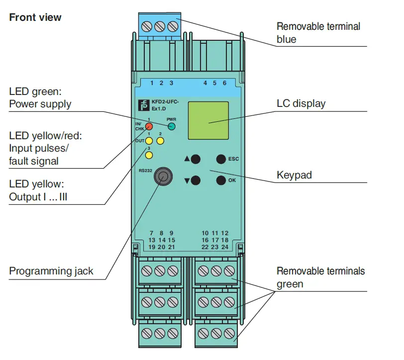
| Indicators/settings | ||
| Display elements | LEDs , display | |
| Control elements | Control panel | |
| Configuration via operating buttons via PACTware | ||
| Labeling space for labeling at the front | ||
| Directive conformity | ||
| Electromagnetic compatibility | ||
| Directive 2014/30/EU | EN 61326-1:2013 (industrial locations) | |
| Low voltage | ||
| Directive 2014/35/EU EN 61010-1:2010 | ||
| Conformity | ||
| Electromagnetic compatibility | NE 21:2006 | |
| Degree of protection | IEC 60529:2001 | |
| Input EN 60947-5-6:2000 | ||
| Ambient conditions | ||
| Ambient temperature | -20 … 60 °C (-4 … 140 °F) | |
| Mechanical specifications | ||
| Degree of protection | IP20 | |
| Connection | screw terminals | |
| Mass 300 g | ||
| Dimensions 40 x 119 x 115 mm (1.6 x 4.7 x 4.5 inch) (W x H x D) , housing type C2 | ||
| Mounting | on 35 mm DIN mounting rail acc. to EN 60715:2001 | |
| Data for application in connection with hazardous areas | ||
| EU-type examination certificate | TÜV 99 ATEX 1471 | |
| Marking | 1 II (1)G [Ex ia Ga] IIC 1 II (1)D [Ex ia Da] IIIC 1 I (M1) [Ex ia Ma] I | |
| Supply | ||
| Maximum safe voltage Um 40 V DC (Attention! Um is no rated voltage.) | ||
| Input I | terminals 1+, 3-: Ex ia | |
| Voltage Uo | 10.1 V | |
| Current Io 13.5 mA | ||
| Power Po 34 mW (linear characteristic) | ||
| Input II | terminals 13+, 14- non-intrinsically safe | |
| Maximum safe voltage Um | 40 V (Attention! The rated voltage can be lower.) | |
| Output I, II terminals 10, 11, 12; 16, 17, 18 non-intrinsically safe | ||
| Maximum safe voltage Um 253 V (Attention! The rated voltage can be lower.) | ||
| Contact loading | 253 V AC/2 A/cos φ > 0.7; 40 V DC/2 A resistive load | |
| Output III | terminals 19+, 20- non-intrinsically safe | |
| Maximum safe voltage Um Um 40 V (Attention! Um is no rated voltage.) | ||
| Output IV terminals 8+, 7- non-intrinsically safe | ||
| Maximum safe voltage | Um | 40 V DC (Attention! Um is no rated voltage.) |
| Interface | RS 232 | |
| Maximum safe voltage Um 40 V (Attention! Um is no rated voltage.) | ||
| Certificate TÜV 02 ATEX 1885 X | ||
| Marking | 1 II 3G Ex nA nC IIC T4 Gc | |
| Output I, II | ||
| Contact loading 50 V AC/2 A/cos φ > 0.7; 40 V DC/2 A resistive load | ||
| Galvanic isolation | ||
| Input I/other circuits | safe electrical isolation acc. to IEC/EN 60079-11, voltage peak value 375 V | |
| Directive conformity | ||
| Directive 2014/34/EU EN 60079-0:2012+A11:2013 , EN 60079-11:2012 , EN 60079-15:2010 | ||
| International approvals | ||
| FM approval | ||
| Control drawing | 16-538FM-12 | |
| UL approval E223772 | ||
| IECEx approval | ||
| IECEx certificate | IECEx TUN 04.0007 IECEx TSA 18.0007X | |
| IECEx marking | [Ex ia Ga] IIC, [Ex ia Da] IIIC, [Ex ia Ma] I Ex ec nC IIC T4 Gc | |
| General information | ||
| Supplementary information Observe the certificates, declarations of conformity, instruction manuals, and manuals where applicable. For information see www.pepperl-fuchs.com. | ||
Assembly
Matching System Components

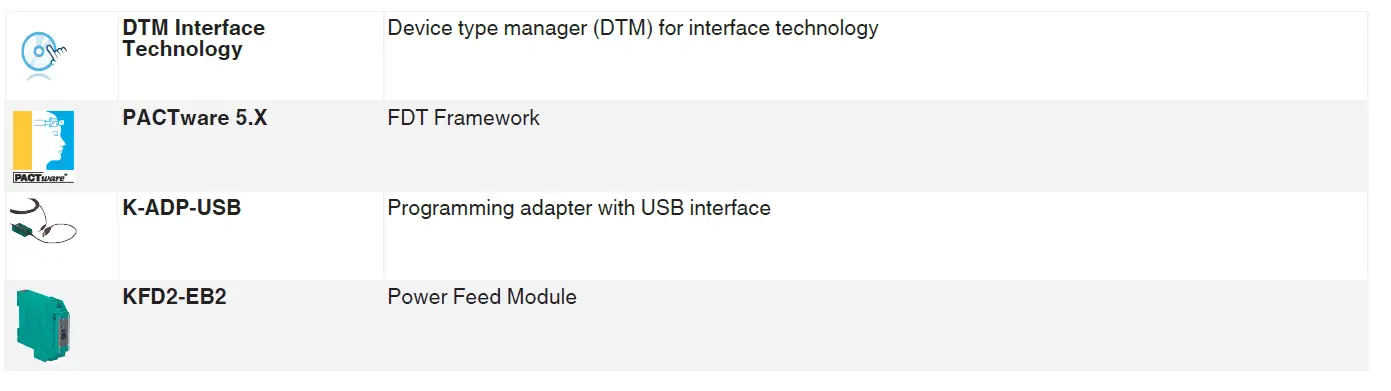
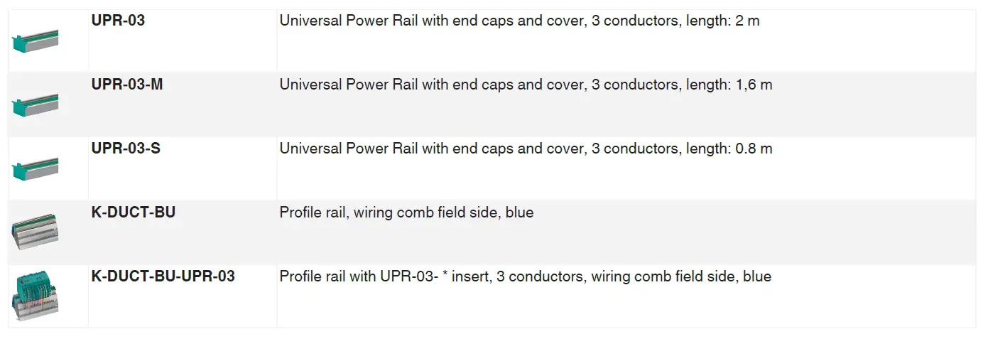
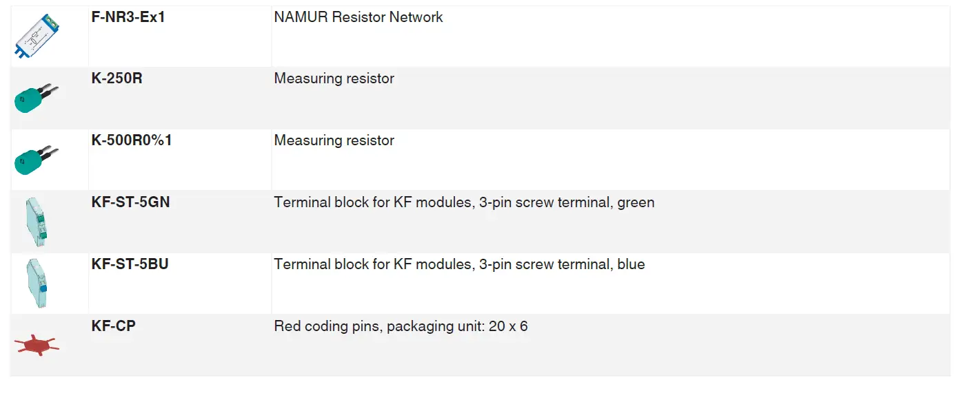
Accessories
Characteristic Curve
Maximum Switching Power of Output Contacts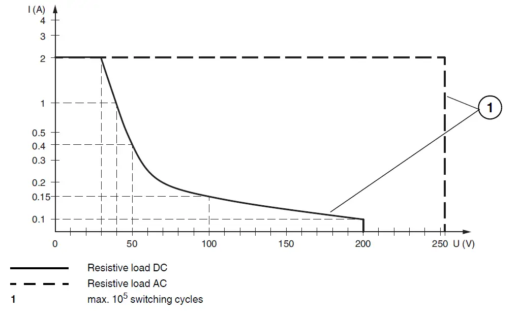
Refer to “General Notes Relating to Pepperl+Fuchs Product Information”.
- Pepperl+Fuchs Group www.pepperl-fuchs.com
- USA: +1 330 486 0002 [email protected]
- Germany: +49 621 776 2222 [email protected]
- Singapore: +65 6779 9091 [email protected]
- Release date: 2022-01-10
- Date of issue: 2022-01-10


