
Veratron B00043501 VL Flex 52 NMEA 2000 Instrument
INTRODUCTION
PACKAGE CONTENTS
| Item number | Description |
| B00043501 | 1x VL Flex 52 |
| A2C5205947101 | 1x 52 mm spinlock nut |
| A2C9582260001 | 1x wiring harness |
| B000100 | 1x safety instructions |
THE ALL-IN-ONE DEVICE
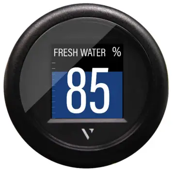
The VL Flex 52 can be easily configured as the display device you need thanks to its 1.44″ TFT display, readable even in strong sunlight, embedded in a standard 52 mm diameter housing. Supported analog inputs allow direct reading from motor sensors, and the NMEA 2000® interface extends this function by allowing the VL Flex to read from the digital network. The simple but effective display layout can be set up in a single or dual layout, presenting the data in a clear and intuitive way, while the colored bar graph and alarm display allow you to interpret the data more quickly.
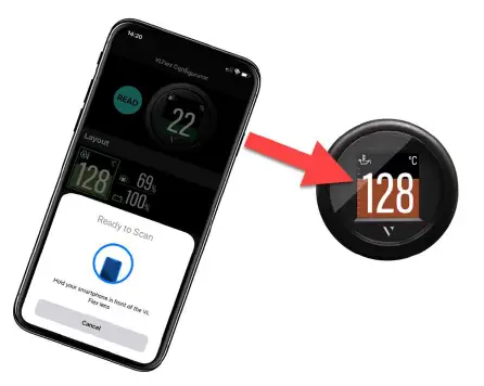
CONTACTLESS CONFIGURATION
Thanks to contactless configuration, you can configure your all-in-one instrument with a simple “tap”! Start the smartphone app and define your settings via the user-friendly interface. Then simply hold your smartphone on the front lens of the VL Flex to transfer the configuration immediately. Thanks to the built-in passive antenna, the configuration can be done without power supply!
SAFETY INFORMATION
WARNING: No smoking! No open fire or heat sources!
- The product was developed, manufactured and inspected according to the basic safety requirements of EC Guidelines and state-ofthe- art technology.
- The instrument is designed for use in grounded vehicles and machines as well as in pleasure boats, including non-classified commercial shipping.
- Use our product only as intended. Use of the product for reasons other than its intended use may lead to personal injury, property damage or environmental damage.
- Before installation, check the vehicle documentation for vehicle type and any possible special features!
- Use the assembly plan to learn the location of the fuel/hydraulic/compressed air and electrical lines!
SAFETY DURING INSTALLATION
- The product was developed, manufactured and inspected according to the basic safety requirements of EC Guidelines and state-ofthe- art technology.
- The instrument is designed for use in grounded vehicles and machines as well as in pleasure boats, including non-classified commercial shipping.
- Use our product only as intended. Use of the product for reasons other than its intended use may lead to personal injury, property damage or environmental damage.
- Before installation, check the vehicle documentation for vehicle type and any possible special features!
- Use the assembly plan to learn the location of the fuel/hydraulic/compressed air and electrical lines!
- Note possible modifications to the vehicle, which must be considered during installation!
- To prevent personal injury, property damage or environmental damage, basic knowledge of motor vehicle/shipbuilding electronics and mechanics is required.
- Make sure that the engine cannot start unintentionally during installation!
- Modifications or manipulations to veratron products can affect safety. Consequently, you may not modify or manipulate the product!
- When removing/installing seats, covers, etc., ensure that lines are not damaged and plug-in connections are not loosened!
- Note all data from other installed instruments with volatile electronic memories.
SAFETY DURING INSTALLATION
- During installation, ensure that the product’s components do not affect or limit vehicle functions. Avoid damaging these components!
- Only install undamaged parts in a vehicle!
- During installation, ensure that the product does not impair the field of vision and that it cannot impact the driver’s or passenger’s head!
- A specialized technician should install the product. If you install the product yourself,wear appropriate work clothing. Do not wear loose clothing, as it may get caught in moving parts. Protect long hair with a hair net.
- When working on the on-board electronics, do not wear metallic or conductive jewelry such as necklaces, bracelets, rings, etc.
- If work on a running engine is required, exercise extreme caution. Wear only appropriate work clothing as you are at risk of personal injury, resulting from being crushed or burned.
- Before beginning, disconnect the negative terminal on the battery, otherwise you risk a short circuit. If the vehicle is supplied by auxiliary batteries, you must also disconnect the negative terminals on these batteries! Short circuits can cause fires, battery explosions and damages to other electronic systems. Please note that when you disconnect the battery, all volatile electronic memories lose their input values and must be reprogrammed.
- If working on gasoline boat motors, let the motor compartment fan run before beginning work.
- Pay attention to how lines and cable harnesses are laid so that you do not drill or saw through them!
- Do not install the product in the mechanical and electrical airbag area!
- Do not drill holes or ports in load-bearing or stabilizing stays or tie bars!
- When working underneath the vehicle, secure it according to the specifications from the vehicle manufacturer.
- Note the necessary clearance behind the drill hole or port at the installation location. Required mounting depth: 65 mm.
- Drill small ports; enlarge and complete them, if necessary, using taper milling tools, saber saws, keyhole saws or files. Deburr edges. Follow the safety instructions of the tool manufacturer.
- Use only insulated tools, if work is necessary on live parts.
- Use only the multimeter or diode test lamps provided, to measure voltages and currents in the vehicle/machine or boat. Use of conventional test lamps can cause damage to control units or other electronic systems.
- The electrical indicator outputs and cables connected to them must be protected from direct contact and damage. The cables in use must have enough insulation and electric strength and the contact points must be safe from touch.
- Use appropriate measures to also protect the electrically conductive parts on the connected consumer from direct contact. Laying metallic, uninsulated cables and contacts is prohibited.
SAFETY AFTER INSTALLATION
- Connect the ground cable tightly to the negative terminal of the battery.
- Reenter/reprogram the volatile electronic memory values.
- Check all functions.
- Use only clean water to clean the components.
- Note the Ingress Protection (IP) ratings (IEC 60529).
ELECTRICAL CONNECTION
- Note cable cross-sectional area!
- Reducing the cable cross-sectional area leads to higher current density, which can cause the cable cross-sectional area in question to heat up!
- When installing electrical cables, use the provided cable ducts and harnesses; however, do not run cables parallel to ignition cables or to cables that lead to large electricity consumers.
- Fasten cables with cable ties or adhesive tape.
- Do not run cables over moving parts. Do not attach cables to the steering column!
- Ensure that cables are not subject to tensile, compressive or shearing forces.
- If cables are run through drill holes, protect them using rubber sleeves or the like.
- Use only one cable stripper to strip the cable. Adjust the stripper so that stranded wires are not damaged or separated.
- Use only a soft soldering process or commercially available crimp connector to solder new cable connections!
- Make crimp connections with cable crimping pliers only. Follow the safety instructions of the tool manufacturer.
- Insulate exposed stranded wires to prevent short circuits.
- Caution: Risk of short circuit if junctions are faulty or cables are damaged.
- Short circuits in the vehicle network can cause fires, battery explosions and damages to other electronic systems. Consequently, all power supply cable connections must be provided with weldable connectors and be sufficiently insulated.
- Ensure ground connections are sound.
- Faulty connections can cause short circuits. Only connect cables according to the electrical wiring diagram.
- If operating the instrument on power supply units, note that the power supply unit must be stabilized and it must comply with the following standard: DIN EN 61000, Parts 6-1 to 6-4.
INSTALLATION
WARNING: Before beginning, disconnect the negative terminal on the battery, otherwise you risk a short circuit. If the vehicle is supplied by auxiliary batteries, you must also disconnect the negative terminals on these batteries! Short circuits can cause fires, battery explosions and damage to other electronic systems. Please note that when you disconnect the battery, all volatile electronic memories lose their input values and must be reprogrammed.
BEFORE THE ASSEMBLY
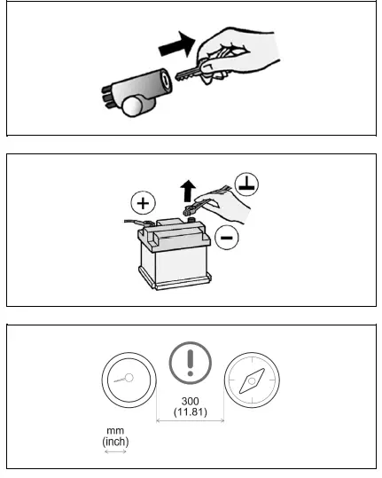
- Before beginning, turn off the ignition and remove the ignition key. If necessary, remove the main circuit switch
- Disconnect the negative terminal on the battery. Make sure the battery cannot unintentionally restart.
- Place the device at least 300 mm away from any magnetic compass.
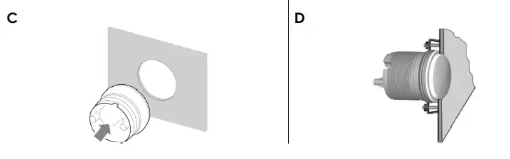
MOUNTING WITH SPINLOCK NUT
- Conventional mounting. (Device is inserted into the hole from the front).
- The panel thickness can be in the range of 0.5 to 20 mm. The hole must have a diameter of 53 mm [B].
WARNING
- Do not drill holes and installation openings in load-bearing or stabilizing struts or spars!
- For the installation location, ensure the necessary clearance behind the holes or the installation opening. Required installation depth 65 mm.
- Pre-drill small installation openings, enlarge with cone cutter, hole saw, jigsaw or file if necessary and finish. Deburr edges. Refer to the safety instructions of the hand tool manufacturer.
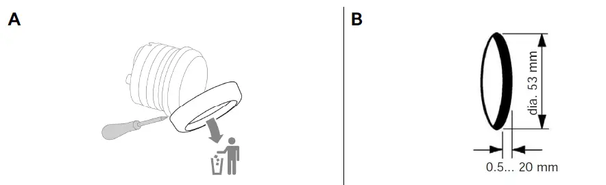
- Different covers can be mounted as an alternative to the supplied cover. In this case, carefully remove it with a screwdriver [A], attach the new bezel to the instrument and press it until it is flush with the cover glass.
Note: When removed, the front ring damaged and can no longer be used be.
IMPORTANT: If you install a chrome bezel, you must set up the device before installation. The metal particles contained in the chrome trim may affect the performance of the wireless interface! - Make a round hole, taking into account the external dimensions of the device. [B]

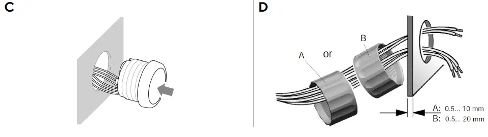
- Remove the spinlock nut and insert the device frontally. [C]
- Align the spinlock nut as shown in [D], according to the thickness of the plate.
- Feed the cables through the spinlock nut and carefully screw it in at least two turns.
- Connect the plugs.
FLUSH MOUNTING
- The recommended panel thickness is 1.5 to 3mm. The hole must have a diameter of 48.1mm [A].
- Make sure that the installation location is level and has no sharp edges.
WARNING
- Do not drill holes and installation openings in load-bearing or stabilizing struts or spars!
- For the installation location, ensure the necessary clearance behind the holes or the installation opening. Required installation depth 65 mm.
- Pre-drill small installation openings, enlarge with cone cutter, hole saw, jigsaw or file if necessary and finish. Deburr edges. Refer to the safety instructions of the hand tool manufacturer.
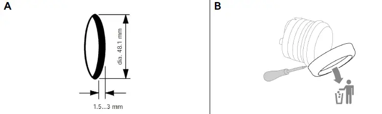
- Make a round hole, taking into account the external dimensions of the device. [A]
- Remove the spinlock nut
- Remove the front ring using a screwdriver. [B]
- Note: When removing, the orifice plate will be damaged and can no longer be used.
- Place the flushmount gasket A2C53215640 (not included) on the cover glass.

- Insert the device into the hole [C] from behind.
- Align the unit so that the reading is straight and fix it to the studs [D] attached to the back of the panel using the flushmount mounting bracket A2C59510864 (not included).
- Connect the plugs.
CONNECTIONS
PINOUT
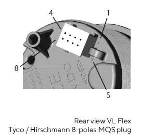
| Pin no. | Cable color | Description |
| 1 | Red | Term. 15 – Battery 12 / 24 V |
| 2 | Black | Term. 31 – Ground |
| 3 | Green / Red | Signal – frequency sensor |
| 4 | Yellow / Red | Signal – resistance sensor |
| 5 | Blue / White | LIN bus |
| 6 | Red / White | Illumination day/night |
| 7 | – | NMEA 2000 High (on M12 connector) |
| 8 | – | NMEA 2000 Low (on M12 connector) |
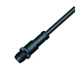
WIRING HARNESS
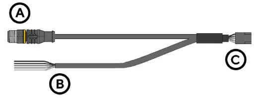
- A: NMEA 2000® DeviceNet M12 5-pin connector
- B: Cables for sensor connection and power supply (see colors in the table)
- C: VL Flex connector – Tyco / Hirschmann MQS 8-pin
NMEA 2000® PINOUT
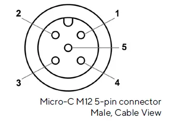
| Pin no. | Description |
| 1 | Shielding |
| 2 | NET-S (V+) |
| 3 | NET-C (V-) |
| 4 | NET-H (CAN H) |
| 5 | NET-L (CAN L) |
CONNECTION TO THE NMEA 2000® NETWORK
- Once mounting is complete, the device can be connected to the NMEA 2000® network via the designated socket on the cabling.
- Make sure to screw the plug all the way on. This is the only way to guarantee that the connection is waterproof.
- A drop cable is only required if the total length of the supplied cabling is not sufficient to reach the NMEA 2000® backbone.
- In this case it is possible to extend the cable with one of the additional drop cables.
- Note that NMEA 2000® does not allow drop cables longer than 6 meters.
- Stick to the NMEA 2000® standard for proper network setup.
FREQUENCY INPUT CONNECTION
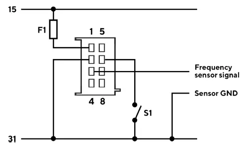
Designations within the connection diagram
- 15: Term. 15 – switched positive 12/24 V (ignition)
- 31: Term. 31 – Mass
- F1: Fuse 3A (not included)
- S1: Illumination switch day/night (not included)
RESISTANCE SENSOR CONNECTION
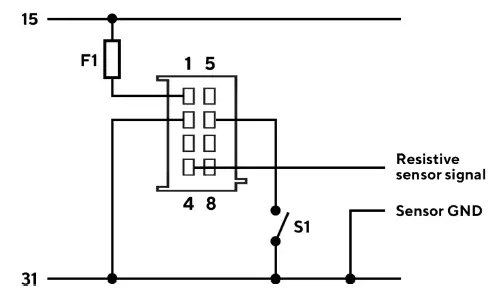
Designations within the connection diagram
- 15: Term. 15 – switched positive 12/24 V (Ignition)
- 31: Term. 31 – Mass
- F1: Fuse 3A (not included)
- S1: Illumination switch day/night (not included)
CONFIGURATION
VL FEX CONFIGURATOR APP
- To configure the VL Flex, some parameters have to be configured, e.g. the display type, the connected sensor and its calibration or the alarm threshold.
- This is possible via the smartphone app “VL Flex Configurator”, which can be downloaded free of charge
from the stores for both Android and iOS devices. - You can also find a simple explanation of the setup process as in-app instructions.
- Thanks to the passive NFC receiver, the VL Flex device can be configured as described below without the need for a power supply.
VL FLEX CONFIGURATOR

CONFIGURE DEVICE
Setting up the VL Flex device is a three-step process. Remember that the configuration of the instrument must be read before it can be changed and written to the instrument.
- READ
- CONFIGURE
- WRITE
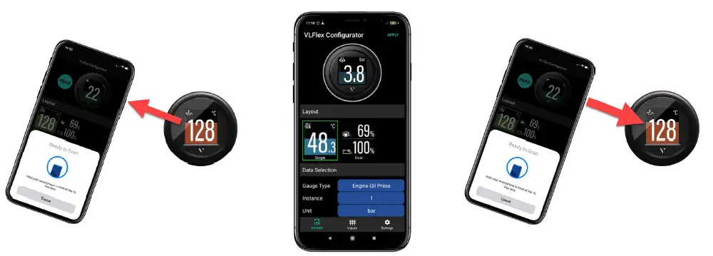
READ CONFIGURATION
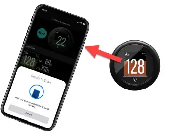
- Open the “VL Flex Configurator” app and read the current configuration of the device by “touching” the front lens of the device with the smartphone.
- The READ operation is mandatory before the WRITE operation is allowed.
- After reading, the app is set with the current configuration of the VL Flex.
Note: The position of the antenna on the smartphone depends on the model. For more information, refer to the smartphone manufacturer’s manual.
SELECT DISPLAY LAYOUT
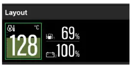
- Use the Layout section to choose between single and double image layouts.
- The preview image at the top of the app screen will update accordingly.
- When Dual Layout is selected, the app expands the device settings to be able to configure both fields of the screen.
SELECT DISPLAY TYPE
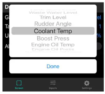
- Use the Gauge Type item in the Data Selection section to select the data to be displayed on the VL Flex.
- If the dual layout is selected, you can select the data for the upper as well as for the lower part of the screen separately.
Note: For the complete list of supported data types, see the Supported Configurations table in this document.
SELECT MASS UNITS AND INSTANCE
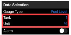
- Define the unit of measurement for the displayed data. (see table “Supported configurations”).
- Set the instance for the displayed data (e.g. engine number or tank number) so that they are shown correctly on the display.
- Some rudder position sensors send their data on their own instance instead of the associated instance of the engine. In this case, the “Ignore” option must be selected as the Engine Instance.
Note: The defined instance is also used by the VL Flex when receiving data from NMEA 2000®.
ALARM SETTINGS
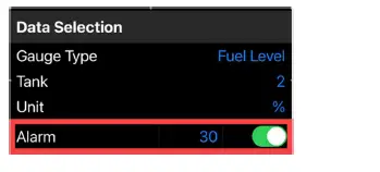
- For some data types an alarm can be set (see table “Supported configurations”).
- The alarm can be activated or deactivated via the corresponding switch in the app.
- Once the option is enabled, the threshold value can be set using the corresponding numeric field.
- The unit of the alarm threshold is the same unit that was defined in the previous step.
Note: The “direction” of the alarm threshold (up or down) is predefined (see table “Supported configurations”).
CALIBRATE SENSOR
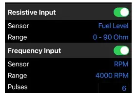
- By default, the VL Flex assumes that data is received via NMEA 2000® , so the analog inputs are disabled.
- If a sensor is connected via an analog connection (resistance or frequency), it can be configured by activating the corresponding switch in the app.
Note: Depending on the type of display configured, only one of the available inputs can be assigned to the data type. (see table “Supported configurations”)
- If a dual layout (two values) has been selected, you can select which data is to be configured as an analog input.
- The other data is considered to be received from the NMEA 2000® network.
LIGHTING AND CLOCK
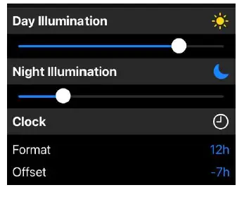
- You can complete the configuration of the VL Flex via the “Settings” tab.
- In this section you can set the intensity of the backlight during the day and night using the slider.
- This screen can also be used to adjust the clock settings (format and offset).
Note: The clock is only received via NMEA 2000® from an external GPS receiver. It is not counted internally by the VL Flex.
TRANSFER CONFIGURATION
- Once the configuration is complete, you can download it to VL Flex.
- Press the “APPLY” button in the upper right corner of the app and “touch” the front lens of the device with your smartphone.
SUPPORTED CONFIGURATIONS
| Display type | Unit | Resistance Sensor | Frequency Sensor | Calibrations | Alarm available | PGN |
| Tachometer | rpm | – ✔ | Pulses per revolution | No | 127488 | |
| Boat speed | kn km/h mph | – ✔ | Pulses per unit | No | 128259 | |
| Ammeter | A | – | – | – | No | 127508 |
| Voltmeter | V | – | – | Measures supply voltage | No | 127508 |
| Battery charge | % | – | – | – | Yes (below) | 127506 |
| Battery status | % | – | – | – | Yes (below) | 127506 |
| Battery temperature | °C °F | – | – | – | Yes (above) | 127508 |
| Battery autonomy | h days | – | – | – | No | 127506 |
| Operating hours | h | – ✔ | Calculated internally | No | 127489 | |
| Speed Over Ground | kn km/h mph | – | – | – | No | 129026 |
| Course Over Ground | deg | – | – | – | No | 129026 |
| Depth | m ft | – | – | – | Yes (below) | 128267 |
|
Fuel level |
% |
✔ |
– | 0 – 90 Ω 3 – 180 Ω 240 – 33 Ω 90 – 4 Ω 105 – 4 Ω | Yes (below) |
127505 |
| Fresh water level | % | ✔ | – | 3 – 180 Ω 240 – 33 Ω 90 – 4 Ω | No | 127505 |
| Waste water level | % | ✔ | – | 3 – 180 Ω 240 – 33 Ω 90 – 4 Ω | No | 127505 |
| Display type | Unit | Resistance Sensor | Frequency Sensor | Calibrations | Alarm available | PGN |
| Trim | % | ✔ | – | 167 – 10 Ω (Single Station) 84 – 5 Ω (Dual Station) | No | 127488 |
| Rudder position | deg | ✔ | – | 10 – 180 Ω (Single Station) 5 – 90 Ω (Dual Station) | No | 127245 |
| Cooling water temp. | °C °F | ✔ | – | 291 – 22 Ω (120 °C) 322 – 19 Ω (150 °C) | Yes (above) | 127489 |
| Boost pressure | bar PSI | ✔ | – | 10 – 184 Ω (2 bar) 10 – 184 Ω (5 bar) | No | 127488 |
| Engine oil pressure | bar PSI | ✔ | – | 10 – 184 Ω (5 bar) 10 – 184 Ω (10 bar) | Yes (below) | 127489 |
| Engine oil temp. | °C °F | ✔ | – | 322 – 19 Ω (150 °C) | Yes (above) | 127489 |
| Transmission oil pressure | bar PSI | ✔ | – | 10 – 184 Ω (10 bar) 10 – 184 Ω (25 bar) 10 – 211 Ω (30 bar) | Yes (below) | 127493 |
| Transmission oil temp. | °C °F | ✔ | – | 322 – 19 Ω (150 °C) | Yes (above) | 127493 |
| Clock | – | – | – | – | No | 126992 |
Supported configurations can be updated at any time. Make sure you always use the latest version of the app.
DISPLAY LAYOUT
SINGLE LAYOUT
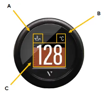
| A. | Symbol Indicates, which data type is displayed right now.
For the data types, which support this function, there is also the instance indicated here. |
| B. | Unit Shows the unit of the currently displayed data. For some data types it’s possible to change the unit in the settings. (See table “Supported Configurations”) |
| C. | Measured value This shows the numeric value of the dedicated measured data. If there aren’t any values received for this data type or they are out of range, the display will show “—“.
Coloured Graph The coloured graphic in the background is a bar diagram that puts the measured value in perspective. This function isn’t supported for all data types. The white lines on the left side show the scalation. |
DUAL LAYOUT
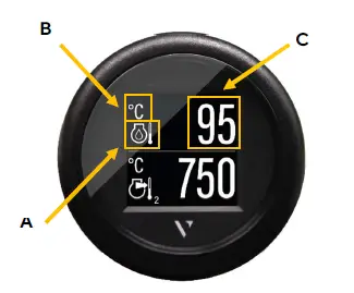
| A. | Symbol Indicates, which data type is displayed right now.
For the data types, which support this function, there is also the instance indicated here. |
| B. | Unit Shows the unit of the currently displayed data. For some data types it’s possible to change the unit in the settings. (See table “Supported Configurations”) |
| C. | Measured Value This shows the numeric value of the dedicated measured data. If there aren’t any data received for this data type or the values are out of range, the display will show “—“.
The bar graph can’t be displayed in the dual layout for any value. |
ALARM DISPLAY
Single data layout
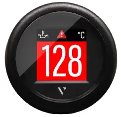
- When an alarm occurs the bar graph turns red, and a red alarm symbol is displayed in the top part of the display between the data symbol and the unit.
- The display returns to normal operation mode once the alarm is not detected anymore.
Dual data layout
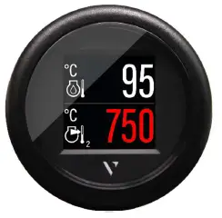
- When an alarm occurs on any of the two displayed data, the numeric digits of the affected data become red.
- In the example above, the data at the bottom of the screen (Exhaust Gas Temperature) has an alarm active.
- The display returns to normal operation mode once the alarm is not detected anymore.
TECHNICAL DATA
DATASHEET
| Screen | 1.44-inch TFT color display, sun-readable, transmissive |
| Screen resolution | 125 x 125 Pixel |
| Rated voltage | 12 V / 24 V |
| Operating voltage | 8 – 32 V with overvoltage and reverse polarity protection |
| Current consumption | 50 mA with maximum illumination intensity |
| Analog inputs | Resistive (0 – 400 Ω) Frequency (W, Ind. , Hall, Generator) |
| Digital inputs | NMEA 2000®, LIN bus |
| Wireless interface | NFC (Near Field Communication) |
| Protection class | IP 67 front side (IEC60529) |
| Cover glass | PMMA with anti-fog and anti-glare coating |
| Housing | Ø52 mm – Polycarbonate (PC), flame retardant (UL94-V0) |
| Front ring | PC (black, white) or ABS (chrome); different colors and shapes |
| Operating temperature | -20°C to +70°C |
| Storage temperature | -30°C to +80°C |
| Connection | Tyco / Hirschmann MQS 8-pole |
| Mounting | Spinlock groove; clamping height 0.5mm – 20mm, Optional bracket and stud bolt, clamping height 2 – 15mm |
| Standards | CE, Reach, RoHS |
SUPPORTED NMEA 2000® PGNS
| Description | PGN |
| ISO Address Claim | 60928 |
| ISO Request | 59904 |
| ISO Transport Protocol, Data Transfer | 60160 |
| ISO Transport Protocol, Connection Management | 60416 |
| ISO Acknowledgment | 59392 |
| NMEA – Request group function | 126208 |
| System Time | 126992 |
| Heartbeat | 126993 |
| Configuration Information | 126998 |
| Product Information | 126996 |
| PGN List – Received PGNs group function | 126464 |
| Rudder | 127245 |
| Fluid level | 127505 |
| DC Detailed Status | 127506 |
| Battery status | 127508 |
| Engine Parameters, Rapid Update | 127488 |
| Engine Parameters, Dynamic | 127489 |
| Transmission Parameters, Dynamic | 127493 |
| Speed, Water Referenced | 128259 |
| Water Depth | 128267 |
| COG & SOG, Rapid Update | 129026 |
ACCESSORIES
| Accessory Part | Part Number |
| Wiring harness with M12 connector | A2C9582260001 |
| Spinlock nut 52 mm | A2C5205947101 |
| Kit for flush mounting | A2C59510864 |
| Gasket for flush mounting | A2C53215640 |
| Front ring – Round Black | A2C5318602701 |
| Front Ring – Round White | A2C5318602801 |
| Front Ring – Round Chrome* | A2C5318602901 |
| Front ring – Triangular Black | A2C5318602401 |
| Front ring – Triangular White | A2C5318602501 |
| Front ring – Triangular Chrome * | A2C5318602601 |
| Front ring – Flat Black | A2C5318604001 |
| Front Ring – Flat White | A2C5318602201 |
| Front ring – Flat Chrome * | A2C5318602301 |
Visit http://www.veratron.com for the complete list of available accessories.
The chrome front ring may interfere with NFC programming due to the metal particles contained in the chrome. Make sure that you configure the VL Flex before installing the chrome front ring!
veratron AG
- Address: Industriestrasse 18 9464 Rüthi, Switzerland
- TEL:+41 71 7679 111
- [email protected]
- veratron.com
Partial or complete distribution, translation or reproduction of this document is strictly prohibited without the prior written consent of veratron AG, with the exception of the following measures:
- Print all or part of the document in its original size.
- Reproduction of the content without modification and explanation by Veratron AG as the copyright holder.
Veratron AG reserves the right to make changes or improvements to the related documentation without prior notice.
Requests for approval, additional copies of this manual, or technical information concerning it should be addressed to veratron AG.


