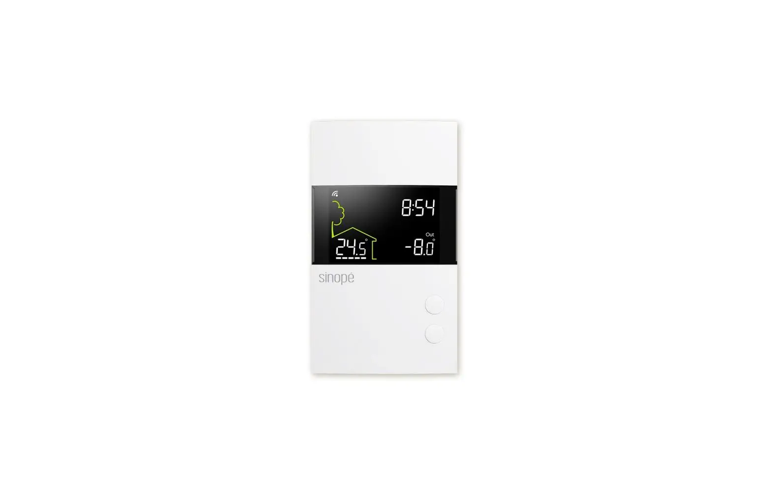
sinope TH1400ZB Smart Low voltage Thermostat Installation Guide
INSTALL YOUR THERMOSTAT
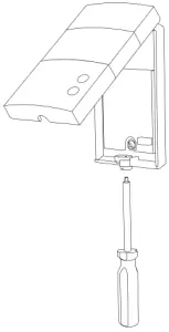
- Unlock and lift the thermostat cover.
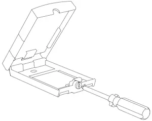
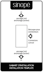
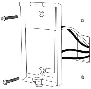
- If necessary, mark and drill the appropriate fastening holes, using the installation template. If needed, use the wall anchors included.
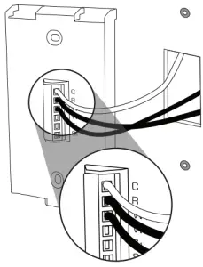
- Depending on the heating system, insert each wire into its terminal and screw firmly. (See connection layouts outlined in the following pages.)
- Use the provided screws and wall anchors to fix the thermostat base on the wall.
- Replace back and lock the thermostat cover.
- Power up the thermostat.

AUXILIARY OUTPUT
The thermostat provides an auxiliary heating output that can act as a second stage of heating when controlling ambient temperature.
If the room temperature is too far from the set point or the main stage of heating has difficulties raising the temperature, the auxiliary output activates the secondary heating source to reach the set temperature.
Both outputs can control different types of heating load and can be configured in the user setting.
Electric floor heating with electric baseboard on the 2nd heating stage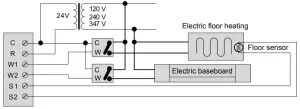
WIRING LAYOUT
- Electric baseboard
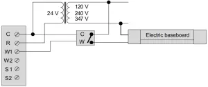
- Hot water valve
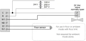
CONNECTION OF THE FLOOR SENSOR (OPTIONAL)
Only for control applications in floor (F) mode or with floor limit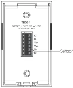
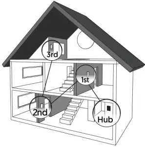
CONNECT YOUR THERMOSTAT TO A ZIGBEE COMPATIBLE SYSTEM
- Initiate the connectivity session of your Zigbee compatible hub by referring to the device’s user guide.
- Connect your thermostat to the network by pressing once the
 and
and  buttons at the same time.
On the thermostat display:
Flashes = Connecting
Remains lit = Connected
If the connectivity fails, the symbol will disappear from the display. Refer to our Website to troubleshoot the unit.
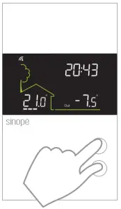
- Connect all your wireless thermostats the same way, by going to the next closest thermostat.
- When all the thermostats are connected, close the connectivity session of your Zigbee compatible hub.
USER SETTINGS
All of the thermostat’s parameters can be set through your compatible Zigbee hub. However, if you have not connected your wireless network and wish to change the temperature format or the control cycle, you need to:
Lower the set point to its minimum and hold the ![]() button for 10 seconds to access the menu.
button for 10 seconds to access the menu.
Press the ![]() or
or ![]() the button to change the setting.
the button to change the setting.
Press the ![]() and
and ![]() the buttons simultaneously to save and go to the next parameter. Continue to press until the end of the list to exit the menu.
the buttons simultaneously to save and go to the next parameter. Continue to press until the end of the list to exit the menu.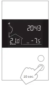
The thermostat features two temperature regulation modes:
Mode Air: Regulation of ambient temperature with the possibility to limit floor temperature through an external temperature sensor.
Mode Flr: Regulation of floor temperature through an external temperature sensor with the possibility to limit ambient temperature.
PARAMETERS THAT CAN BE CONTROLLED FROM THE DEVICE:
# | Name | Parameters & settings | Display |
1 | Temp | Temperature format °C or °F – (Default: °C) |
|
2 | Control | Control mode of thermostat A (Air), F (Floor) – (Default: A) |  |
| 3 | Max Air | Maximum ambient temperature limit 5 °C to 36 °C – (Default OFF) |
|
4 | Max Floor | Maximum floor temperature limit 7 °C to 36 °C – (Default: OFF) (4) |
|
| 5 | Min Floor | Minimum floor temperature limit 5 °C to 36 °C – (Default OFF) |
|
6 | Cyc | Cycle lenght / Main output 15 sec, 5 min, 10 min, 15 min, 20 min, 25 min, 30 min – (Default: 15 min) (1) |  |
| 7 | Aux Cyc | Cycle lenght / Auxiliary output OFF, 15 sec, 5 min, 10 min, 15 min, 20 min, 25 min, 30 min – (Default: OFF) (1) |
|
8 | Sens | Floor sensor 10K or 12K – (Default: 10K) |  |
| 9 | PE | Circulator pump’s anti-seizure ON or OFF (Default: OFF) (5) |
|
PARAMETERS THAT CAN BE CONTROLLED FROM THE DEVICE (CONTINUED):
Maximum floor temperature limit (Mode Air)
The thermostat limits floor heating to the set temperature to ensure it does not exceed the selected limit. This parameter is ideal for protecting engineered wood floors. (Verify with your flooring manufacturer to determine heat limit.)
This parameter is only usable when a floor sensor is connected to the thermostat.
Main and auxiliary output cycle length
The thermostat has a main and an auxiliary output. Select the appropriate cycle length based on your heating system. The selection of an inappropriate cycle length may damage your unit.
Minimum cycle length | 0.15 | 5 | 10 | 15 | 20 | 25 | 30 |
Convector or baseboard heater activated by electronic relay (SSR) | X | ||||||
| Fan-forced convector activated by electronic relay (SSR) | X | X | |||||
Fan-forced convector or baseboard heater activated by mechanical relay | X | X | |||||
| Hydronic heating pump system | X | X | X | X | |||
Furnace | X | X | X | X |
Circulator pump’s anti-seizure
When the thermostat is not heating for an extended period, this parameter will activate the main output during 1 minute every 24 hours to ensure the hydronic system pump does not seize.
DISCONNECT YOUR THERMOSTAT FROM A ZIGBEE COMPATIBLE SYSTEM
To disconnect your thermostat from the Zigbee compatible hub, press the ![]() and
and ![]() buttons simultaneously for 10 seconds. The
buttons simultaneously for 10 seconds. The ![]() symbol will disappear from the display.
symbol will disappear from the display.
TECHNICAL SPECIFICATIONS
- Operating voltage: 24 Vac
- Maximum load: 1 Amp
- Set point range: 5 ˚C to 36 ˚C (41 ˚F to 96 ˚F)
- Display range: 0 ˚C to 70 ˚C (32 ˚F to 99 ˚F)
- Resolution: ± 0,5 ˚C (± 1 ˚F)
- Storage: -20 ˚C to 50 ˚C (-4 ˚F to 122 ˚F)
- Zigbee profile 3.0
- Frequency: 2.4 GHz
- Transmission power: +20 dBm
- Receiver sensitivity: -108 dBm
Compatible with
- Baseboard heater activated by electronic relay (SSR)
- Baseboard heater activated by mechanical relay
- Fan-forced convector
- Electric floor heating (activated by a relay)
- Hydronic floor heating
- Hydronic heating system
- Furnace (without fan control)
Transmitter Module IC : 22394-ZBM1501 / FCC ID:2AK2T-ZBM1501
This device complies with Industry Canada license exempt RSS standard(s).
Operation is subject to the following two conditions:
- this device does not cause interference, and
- this device must accept any interference, including interference that may cause undesired operation of the device.
This equipment has been tested and found to comply with the limits for a Class B digital device, pursuant to part 15 of the FCC Rules. These limits are designed to provide reasonable protection against harmful interference in a residential installation. This equipment generates, uses and can radiate radio frequency energy, and if not installed and used in accordance with the instructions, may cause harmful interference to radio communications. However, there is no guarantee that interference will not occur in a particular installation. If this equipment does cause harmful interference to radio or television reception, which can be determined by turning the equipment OFF and ON, the user is encouraged to try to correct the interference by one or more of the following measures:
- Reorient or relocate the receiving antenna.
- Increase the separation between the equipment and receiver.
- Connect the equipment into an outlet on a circuit different from that to which the receiver is connected.
- Consult the dealer or an experienced radio/TV technician for help.
3-year limited warranty
SINOPE TECHNOLOGIES INC. warrants the components of their products against defects in material and workmanship for a 3-year period from the date of purchase, under normal use and service, when proof of purchase of such is provided to the manufacturer. This warranty does not cover any transportation costs that may be incurred by the consumer. Nor does it cover a product that has been improperly installed, misused or accidentally damaged.
The obligation of SINOPÉ TECHNOLOGIES INC., under the terms of this warranty, will be to supply a new unit and this releases the manufacturer from paying the installation costs or other secondary charges linked to replacing the unit or the components.
 For more information, visit our Website: www.sinopetech.com


 Smart Thermostat For Electric Heating Instruction Manual")


 Instruction Manual")


