Braukmann BA295S
Keep instructions for later use!
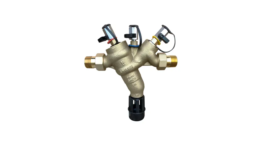
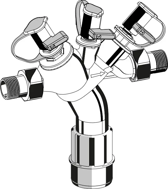
Backflow Preventer
Safety Guidelines
- Follow the installation instructions.
 The factory-set position of the ball valves may not be altered. Non-compliance with this instruction will make any warranty claims null and void.
 - Use the appliance
• according to its intended use
• in good condition
• with due regard to safety and risk of danger. - Note that the appliance is exclusively for use in the applications detailed in these installation instructions. Any other use will not be considered to comply with requirements and would invalidate the warranty.
- Please take note that any assembly, commissioning, servicing and adjustment work may only be carried out by authorized persons. Immediately rectify any malfunctions which may influence safety.
Description of function
BA-type backflow preventers are divided into three pressure zones. The pressure in the zone 1 is higher than in the zone, which in turn is higher than in the zone 3. A discharge valve is connected to a zone 2 which opens at the latest when the differential pressure between zones 1 and 2 drops to 0.14 bar. The water from the zone discharges to the atmosphere, both check valves close and therefore separate zone 2 from zone 1 and 3. In this way, the danger of backpressure or back-siphonage into the supply network is prevented. The pipework connection is interrupted and the drinking water network is protected.
Application
| Medium | Water |
| Maximum inlet pressure | 10.0 bar |
| Minimum inlet pressure | 1.5 bar |
Technical data
Installation position Horizontal with discharge valve downwards
| Max. operating temperature | 65 °C (WRAS 60 °C) |
| Discharge pipe connection | DN50 for connection sizes 1/2″ – 11/4″ DN70 for connection sizes 11/2″ – 2″ |
| Connection size | 1/2″ – 2″ |
Scope of delivery
The backflow preventer consists of:
- Housing
- Integrated strainer, mesh size approx. 0.2 mm
- Valve cartridge with integrated check valve and discharge valve
- Outlet check valve
- Three ball valves for the connection of a differential pressure gauge
- Connection fittings
- Discharge connection
Options
BA295S-… A = Standard version acc. EN12729 with threaded connections 1/2″ – 2″
BA295S-1B = Special version with threaded connections 1″
BA295S-… AGB = Standard version acc. EN12729, all materials acc. WRAS, with threaded connections 1/2″ – 2″
Assembly
Installations Guidelines
- Install shutoff valves before and after the backflow preventer
- Install in horizontal pipework with thedischarge valve downwards
- Ensure good access
- Simplifies maintenance and inspection
- If a fine filter is not installed in the drinking water system, the installation of a filter with a mesh width of 100µ m is recommended in front of the backflow preventer.
- In the case of fluctuating pre-pressure or an input pressure over 10 bar, we recommend the insertion of a pressure regulator in front of the backflow preventer.
- Do not install in places where flooding can occur
- The installation environment should be protected against frost and ventilated well. Do not install in polluted atmosphere, for example, toxic vapor, aerosol, gas or dust
- Install discharge pipework that has adequate capacity
 Use and type of installation according to EN 1717
Assembly instructions
- Thoroughly flush pipework
- Install backflow preventer
• Install in horizontal pipework with discharge connection directed downwards
• Note flow direction (indicated by arrow)
• Install without tension or bending stresses
• Provide a straight section of pipework of at least five times the nominal valve size after the backflow preventer - Attach drain pipe to discharge connection (plastic pipe HT 50, HT 70)
- The appliance is ready for use
Maintenance
![]() We recommend a planned maintenance contract with an installation company
We recommend a planned maintenance contract with an installation company
![]() Maintenance of the backflow preventer must be carried out by authorized personnel!
Maintenance of the backflow preventer must be carried out by authorized personnel!
Inspection – acc. EN806-5
![]()
- Frequency: every 6 months (depending on local operating conditions)
- To be carried out by an installation company
- Inspection with a test control unit and maintenance set (see accessories)
- Testing discharge valveTest with a test kit
1. Procedure according to local requirements Quick test for the discharge valve:
• Lower the inlet pressure
– if the discharge valve opens (it drops), the function is o.k. - Testing outlet check valve Test with the test kit
1. Procedure according to local requirements
Maintenance
![]() We recommend a planned maintenance contract with an installation company
We recommend a planned maintenance contract with an installation company
In accordance with EN 806-5 a regular maintenance must be taken.![]() Frequency: every 1-3 years (depending on local operating conditions)
Frequency: every 1-3 years (depending on local operating conditions)
To be carried out by an installation company
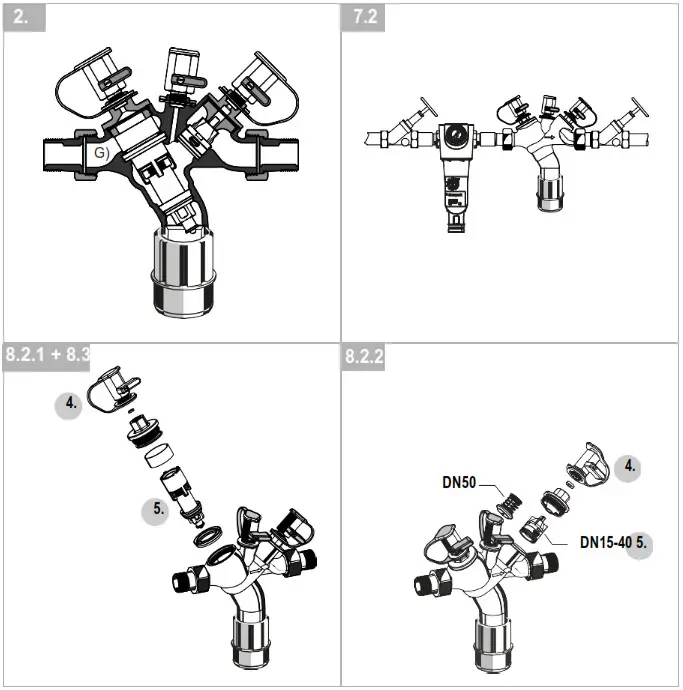
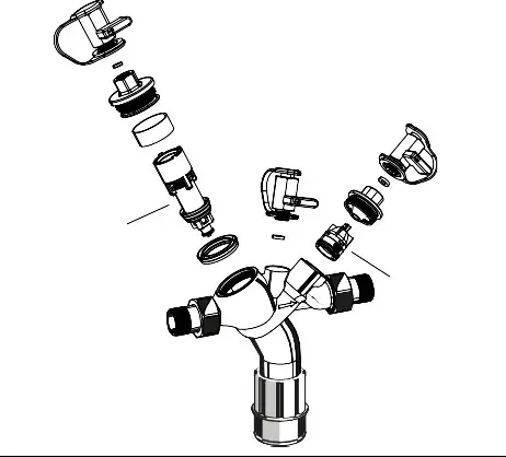
- Cartridge insert
1. Close shutoff valve on the inlet
2. Release pressure on the outlet side (e.g. through water tap)
3. Close shutoff valve on the outlet
4. Remove cover
5. Replace cartridge insert and lip seal • Don’t disassemble cartridge insert to individual parts!
6. Reassemble in reverse order · push down the cartridge insert till it snaps in
7. Test function (see chapter inspection) - Check valve
1. Close shutoff valve on the inlet
2. Release pressure on the outlet side (e.g. through water tap)
3. Close shutoff valve on the outlet
Caution DN50 is under spring tension.
The unsnapping of the lid can cause physical injuries.
4. Remove cover
5. Exchange check valve
6. Reassemble in reverse order
7. Test function (see chapter inspection)
Cleaning
![]()
- To be carried out by an installation company
- To be carried out by the operator
If necessary, the cartridge insert can be cleaned. Do not use any cleaners that contain solvents and/or alcohol for cleaning the plastic parts, because this can cause damage to the plastic components – water damage could result. Detergents must not be allowed to enter the environment or the sewerage system!
- A close shutoff valve on the inlet
- Release pressure on the outlet side (e.g. through water tap)
- A close shutoff valve on the outlet
- Remove cover
- Clean or replace cartridge insert and lip seal
• Don’t disassemble cartridge insert to individual parts! - Reassemble in reverse order · push down the cartridge insert till it snaps in
- Test function (see chapter inspection)
Disposal
- DZR brass housing
- Valve cartridge in high-grade synthetic material
- An outlet check valve in high-grade synthetic material for connection size 1/2″ – 1 1/2″, an outlet check valve in dezincification resistant brass for connection size 2″
- Brass ball valves
- Sealing elements made of elastomer materials suitable for drinking water
- Discharge connection in high-grade synthetic material Observes the local requirements regarding correct waste recycling/disposal!
Troubleshooting
| Disturbance | Cause | Remedy |
| The discharge valve opens without apparent reason | Pressure strokes in the water supply system | Install a pressure reducing valve upstream the backflow preventer |
| Fluctuating inlet pressure | Install a pressure reducing valve upstream the backflow preventer | |
| Cartridge insert is contaminated | Remove cartridge insert and exchange it | |
| The discharge valve doesn’t close | Deposits on the valve seat | Remove cartridge insert and clean or exchange it |
| Damaged ’ring | Remove cartridge insert and exchange it | |
| Leaky discharge valve | Remove cartridge insert and clean or exchange it | |
| The discharge valve doesn’t close | The inlet strainer is blocked | Remove strainer and clean it |
Spare Parts
| No. | Description | Dimension | Part No. |
| 1 | Cartridge insert complete | ½”, ¾”, 1″ B-Version1″ A-Version, 1¼” 1½”, 2″ | 904141 0904142 0904143 |
| 2 | Check valve | ½”, ¾”, 1″ B-Version 1″ A-Version 1¼” 1½” 2″ | 0904144 0904145 0904146 0904147 0904148 |
Accessories
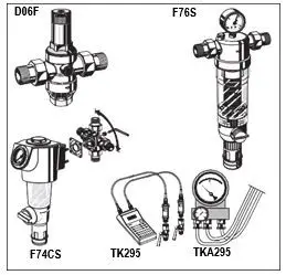
| D06F | Pressure reducing valve Noise protected pressure reducing valve with setting scale. Maximum inlet pressure 16 bar, with brass filter bowl 25 bar, outlet pressure range 1.5 – 6.0 bar A = With clear filter bowl up to 40 °C / 16 bar B = With brass filter bowl up to 70 °C / 25 bar |
| TK295 | Test kit Electronic pressure measuring device with digital indicator, battery-operated. With case and accessories, ideal for inspection and maintenance of backflow preventer type BA. |
| TKA295 Test kit | Analog pressure measuring device with differential pressure display. With case and accessories, ideal for inspection and maintenance of backflow preventer type BA. |
| F76S | Fine filter, reverse rinsable AA= With clear filter bowl AAM = With red bronze filter bowl |
| F74CS | Fine filter Reverse rinsable fine filter with a rotatable connection piece |
www.resideo.com | Ademco 1 GmbH Hardhofweg 40 74821 Mosbach Phone: +49 1801 466 388 [email protected] homecomfort.resideo.com | @2020 Resideo Technologies, Inc. All rights reserved. This product is manufactured by Resideo Technologies, Inc and its affiliates. |


