![]() 2A8 KCPE 900 Wifi Bridge
2A8 KCPE 900 Wifi Bridge
User Guide
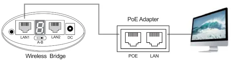
Hardware Connection
Take the 5.8G1000M as an example
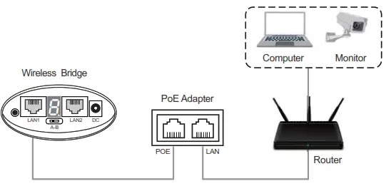
Description of keys and interfaces
| Keys/Interfaces | Description |
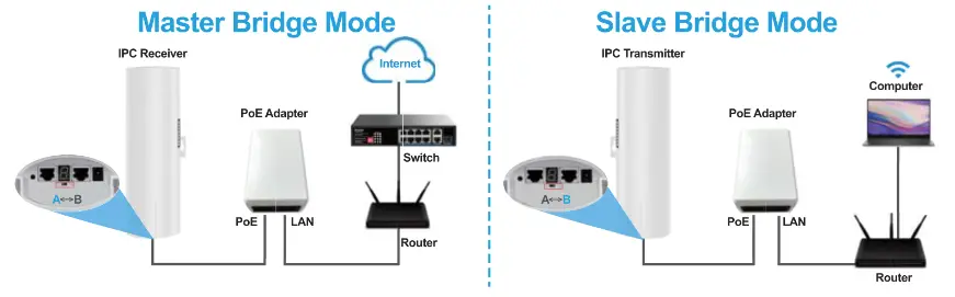
| A<->B | Working mode A: Master Mode B: Slave Mode |
| DC | DC power supply interface. The device supports 12V/1A DC power supply access. |
| Digital switch/ Reset switch | Press briefly during power-up to add one to the digital tube value (the digital tube configuration takes approximately 3 seconds to take effect). Press and hold for 15 seconds during power-up, the device will return to the original factory settings. |
| 2.4G 300M Wireless Bridge | |
| LAN | Data transmission and power supply port, the network port acts as a LAN port in bridge mode, connect POE power adapter POE port. |
| 5.8G 300M Wireless Bridge | |
| LAN1 | Data transmission and power supply port, the network port acts as a LAN port in bridge mode, connect POE power adapter POE port. |
| LAN2 | Data transmission and power supply port, the network port acts as LAN port in bridge mode, connect POE power adapter POE port |
| 5.8G 1000M Wireless Bridge | |
| LAN1 | LAN data transmission port, port rate 10/100M adaptive, can be connected to computers, cameras, switches and other devices |
| LAN2 | Data transmission and power supply port, port rate 10/100/1000M adaptive, bridge mode network port acts as LAN port function, connect POE power adapter POE port |
Digital bridge pairing settings
3.1 Pairing settings
- A B mode is set via the A-B dip switch, the led appears and flashes L. When the L disappears the configuration remains successful.
- The led digital display is set via the RESET button, pressed once to activate the configuration state and pressed again to increase it automatically. It can be increased continuously.
For example, to configure a pair of bridges with the number “1”, set up the bridge as follows.
- After setting A to “1”, set B to “1”. The LED will blink first, please wait patiently.
- After the L blinks into the number “1”, “1” will continue to blink until the LED shows “1” is always on and no longer blinks, at this time A-B has been successfully networked.
3.2 Digital switch for quick pairing
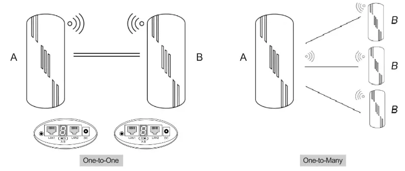
One-to-one matching method
- Dial one bridge to “A” and the other bridge to “B”.
- Short press the digital on/off/reset button, each press will add one to the digital tube value.
- Set the paired bridge to the same value for successful pairing.
One-to-many pairing method (up to 1 pair of 8)
- Dial one bridge to “A” and the others to “B”.
- Short press the “digital switch/reset” button, each press adds one to the value of the digital tube.
- Set the paired bridge to the same value for successful pairing.
3.3 Bridge setup via browser
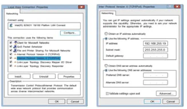
Computer Settings
- Right click “Local Area Connection” and select “Properties”.
- In the Properties dialog box double click on “Internet Protocol Version 4(TCP/IPv4)”.
- Select “Use the following IP address”. Set the IP address to 192.168.255.X (X is any number from 2-253) and the Subnet mask to 255.255.255.0. Then click “OK”.
Advanced Settings – Custom Settings
- Turn off the digital display and set the mode and pairing network ID via the web page.
- The computer settings are attempted as follows.

- Configure the IP address of the PC, the IP address configured for the PC is 192.168.255.X.
- Open Google Chrome and type the IP address of the bridge into the IE address bar. IP address please refer to Appendix I: Comparison table of pairing settings.
- Enter the following login management interface operation:
- The device is in bridge mode by default, open the computer browser, (when the dip switch is in A, the digital display shows the number “5” for example), set the IP address 192.168.255.105.
- In the device management platform, User name/Password is “admin”, then click “login”.
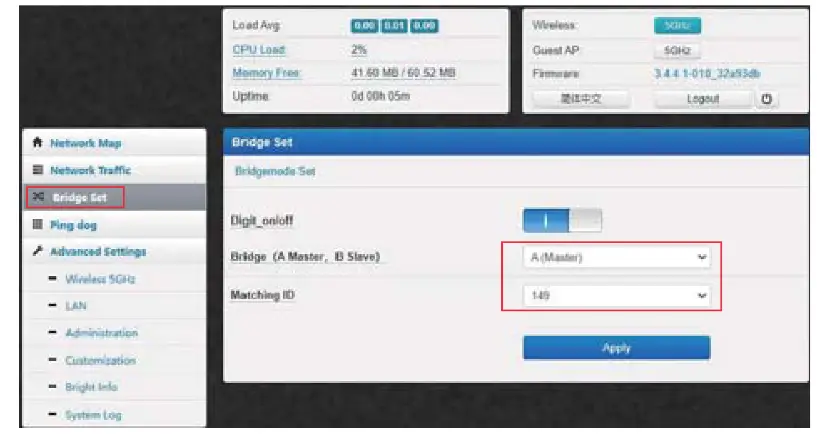
- In the [Bridge Set] screen, you can turn off the digital display function.
- Master bridge configuration method:
- Click “Bridge Set”.
- Set the bridge mode to A mode.
- Set the ID number.
- Click “Apply” and the configuration will take effect.

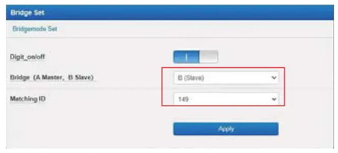
- Slave bridge configuration method
- Click “Bridge Set”.
- Set the bridge mode to B mode.
- Set the ID number(The ID number should match the ID number of the paired A device).
- Click “Apply” and the configuration will take effect.
Appendix I: Comparison table of pairing settings
| Digital display | Corresponding ID | Management IP of A | Management IP of B |
| 0 | 0 | 192.168.255.100 | 192.168.255.200 |
| 1 | 165 | 192.168.255.101 | 192.168.255.201 |
| 2 | 161 | 192.168.255.102 | 192.168.255.202 |
| 3 | 157 | 192.168.255.103 | 192.168.255.203 |
| 4 | 153 | 192.168.255.104 | 192.168.255.204 |
| 5 | 149 | 192.168.255.105 | 192.168255.105 |
| 6 | 48 | 192.168.255.106 | 192.168.255.206 |
| 7 | 44 | 192.168.255.107 | 192.168.255.207 |
| 8 | 40 | 192.168.255.108 | 192.168.255.208 |
| 9 | 36 | 192.168.255.109 | 192.168.255.209 |
| A | 140 | 192.168.255.110 | 192.168.255.210 |
| B | 132 | 192.168.255.111 | 192.168.255.211 |
| C | 124 | 192.168.255.112 | 192.168.255.212 |
| D | 116 | 192.168.255.113 | 192.168.255.213 |
| E | 108 | 192.168.255.114 | 192.168.255.214 |
| F | 100 | 192.168.255.115 | 192.168.255.215 |
Appendix II: Product Parameter
| Model | CPE-S300 |
| Main Chipset | AR9344 |
| Flash | 8MB |
| Memory | 64MByte DDR2 |
| Interface | 2 x 10/100Mbps Adaptive RJ45 network interface(support 24V PoE) |
| Wireless Technology | 5G:450M 802.11a/n/ac 1T1R technology |
| Power consumption | 24V 0.5A Passive PoE DC 12V 1A,<10W |
| Antenna | Built-in high gain 14dBi directional panel antenna (horizontal wave half-angle 60°, vertical wave half-angle 60°) |
| Frequency range | ISM band: 4.900GHz — 5.850GHz |
| Channel Distribution | 5G:36、40、44、48、52、56、60、64、100、104、108、112、116、120、124、 128、132、136、140、149、153、157、161、165 |
| Output power | 11a @54M:20±2dB,@6M:23±2D; 11n 20MHz:@MCS9:20±2dB,@MCS0:23±2dB; 11n 40MHz: @MCS9:20±2dB,@MCS0:23±2dB;11ac 40MHz @MCS9:20±2dB,@MCS9:20±2dB;11ac 80MHz @MCS9:20±2dB,@MCS0:23±2Db |
| Reception Sensitivity | 11a: <-72dbm@54Mbps,<-89dbm@6Mbps;11n 20MHz: <-89dbm@MCS0;1ac 40MHz:<-66dbm@MCS9,<-84dbm@MCS0;11ac 80MHz: <-63dBm@MCS9,<-81dBm@MCS0 |
| EVM | 802.11n: 5 -28 dB,802.11a: 5 -25 dB |
| PPM | <±20ppm |
| Throughput | 300Mbps |
| Bridge Configuration | Wireless mode: Bridge Access Point, Bridge Client Switching Bridge Access Point: Bridge SSID, encryption method (WPA2-PSK, WPA-PSK, no encryption), bridge password, wireless protocol, wireless bandwidth, wireless channel, wireless power (100%, 75%, 50%, 25%, 10%, 5%) Bridge client: Bridge SSID, encryption method (WPA2-PSK, WPA-PSK, no encryption), bridge password, MAC address lock at the other end, wireless channel, wireless power (100%, 75%, 50%, 25%, 10%, 5%) |
| Working mode | Master AP (bridge access point), slave AP (bridge client), switchable via dip switches |
| Environment | Operating Temperature: -30-55 °C; Storage Temperature: -40-70 °C; Operating Humidity: 10%-90% non-condensing; Storage Humidity: 5%-95% non-condensing |
| Model | CPE-S900 |
| Main Chipset | MTK7620A+7621 E+ IP1001 M 900Mbps |
| Flash | 8MB |
| Memory | 64MByte DDR2 |
| Interface | WAN:1*10/100/1000 Mbps Adaptive RJ45 Network Interface LAN:1*10/100Mbps Adaptive RJ45 Network Interface |
| Wireless Technology | 5G:900M 802.11a/n/ac MIMO technology |
| Power Consumption | 24V 0.5A Passive PoE DC 12V 1A,<10W |
| Antenna | Built-in high gain 14dBi directional panel antenna (horizontal wave half-angle 60°, vertical wave half-angle 60°) |
| Frequency Range | ISM band: 4.900GHz – 5.850GHz |
| Channel Distribution | 5G:36、40、44、48、52、56、60、64、149、153、157、161 |
| Output Power | 11a @54M:20±2dB, @6M:23±2Db 11n 20MHz: @MCS7:23±2dB, @MCS0:23±2dB 11 n 40MHz: @MCS7:20±2dB, @MCS0:23±2dB 11 ac 40MHz @MCS7:20±2dB, @MCS0:23±2dB 11a c 80MHz @MCS7:20±2dB, @MCS0:23±2Db |
| Reception Sensitivity | 11a: -65dbm@54Mbps, -81dbm@6Mbps 11n 20MHz: -64dbm@MCS7, -82dbm@MCSO 11ac 40MHz: -61dbm@MCS7, -79dbm@MCSO 11ac 80MHz: -58dBm@MCS7 -76dBm@MCSO |
| EVM | 802.11n: 5 -28 dB 802.11a: 5 -25 dB |
| PPM | <±20ppm |
| Throughput | 300Mbps |
| Network | Bridge: Static IP/Dynamic Acquisition Gateway: Static IP/Dynamic Acquisition/PPPoE |
| Working Mode | Master AP, Slave AP (dial switch) |
| Environment | Operating Temperature: -30~55 °C; Storage Temperature: -40~70 °C; Operating Humidity: 10%~90% non-condensing; Storage Humidity: 5%~95% non-condensing |
FCC Warning Statement
Changes or modifications not expressly approved by the party responsible for compliance could void the user s authority to operate the equipment. This equipment has been tested and found to comply with the limits for a Class B digital device, pursuant to Part 15 of the FCC Rules. These limits are designed to provide reasonable protection against harmful interference in a residential installation. This equipment generates uses and can radiate radio frequency energy and, if not installed and used in accordance with the instructions, may cause harmful interference to radio communications. However, there is no guarantee that interference will not occur in a particular installation. If this equipment does cause harmful interference to radio or television reception, which can be determined by turning the equipment off and on, the user is encouraged to try to correct the interference by one or more of the following measures:
- Reorient or relocate the receiving antenna.
- Increase the separation between the equipment and receiver.
- Connect the equipment into an outlet on a circuit different from that to which the receiver is connected.
- Consult the dealer or an experienced radio/TV technician for help.
This device complies with part 15 of the FCC Rules. Operation is sub ect to the following two conditions:
- This device may not cause harmful interference, and
- this device must accept any interference received, including interference that may cause undesired operation.
RF Exposure Statement
To maintain compliance with FCC s RF Exposure guidelines, This equipment should be installed and operated with minimum distance of 20cm the radiator your body. This device and its antenna(s) must not be co-located or operation in con unction with any other antenna or transmitter.
![]() Shenzhen Lixunlian Technology Co., Ltd.
Shenzhen Lixunlian Technology Co., Ltd.
729, 7th Floor, Tianhe Building, Dongguan 1st Road, Faking Community,
Longhua Street, Longhua District, Shenzhen, Guangdong, China
[email protected]


