RUIJIE RG-EST350 Series Wireless Bridges User Guide

Copyright statement
Ruijie Networks©2021
Ruijie Networks reserves all copyrights of this document. Any reproduction, excerption, backup, modification, transmission, translation or commercial use of this document or any portion of this document, in any form or by any means, without the prior written consent of Ruijie Networks is prohibited.
Exemption statement
This document is provided “as is”. The contents of this document are subject to change without any notice. Please obtain the latest information through the Ruijie Networks website. Ruijie Networks endeavors to ensure content accuracy and will not shoulder any responsibility for losses and damages caused due to content omissions, inaccuracies or errors.
Preface
Thank you for using our products. This manual will guide you through the installation of the device.
Scope
It is intended for the users who have some experience in installing and maintaining network hardware. At the same time, it is assumed that the users are already familiar with the related terms and concepts.
Obtaining Technical Assistance
Ruijie Networks Website: https://www.ruijienetworks.com/
Technical Support Website: https://ruijienetworks.com/support
Case Portal: https://caseportal.ruijienetworks.com
Community: https://community.ruijienetworks.com
Technical Support Email: [email protected]
Skype: [email protected]
| Documents | Description |
| Configuration Guide | Describes network protocols and related mechanisms that supported by the product, with configuration examples. |
| Command Reference | Describes the related configuration commands, including command modes, parameter descriptions, usage guides, and related examples. |
Documentation Conventions
The symbols used in this document are described as below This symbol brings your attention to some helpful suggestions and references.
![]() This symbol means that you must be extremely careful not to do some things that may damage the device or cause data loss.
This symbol means that you must be extremely careful not to do some things that may damage the device or cause data loss.
1 Product Overview
RG-EST350 is an 802.11ac wireless bridge designed for video postback scenario. Its 5GHz radio delivers an access rate of 866Mbps.
The IP65 design adapts to inclement outdoor environments such as the cold and humidity. This substantially simplifies installation and maintenance.
1.1 Technical Specifications
Table 1-1 RG-EST350 Technical Specifications
| Model | RG-EST350 |
| Chip | QCA9563+QCA9886 |
| Memory/Flash | 512MB/8MB |
| RF Design | Single-band Dual-stream 2×2 |
| Transmission Protocol | 802.11ac wave2 |
| Bands | 802.11a/n/ac: 5G (Country-specific) |
| Antenna | Directional antenna, horizontal 31°, vertical 14° |
| Bridging Distance | 5km |
| Spatial Streams | 2 streams |
| Max Throughput | 5GHz: 866Mbps |
| Modulation | OFDM: BPSK@6/9Mbps, QPSK@12/18Mbps, 16-QAM@24Mbps, 64-QAM@48/54Mbps OFDM: BPSK, QPSK, 16QAM, 64QAM, 254QAM |
| Receive Sensitivity | 11a: -89dBm (6Mbps), -80dBm (24Mbps), -76dBm (36Mbps), -71dBm (54Mbps) 11n: -83dBm@MCS0, -65dBm@MCS7, -83dBm@MCS8, -65dBm@MCS15 11ac: -86dBm@MCS0, -63dBm@MCS9 |
| Transmit Power | ≤320mw (adjustable) |
| Adjustable Power | 1dBm |
| Dimensions (W x D x H) | 230 mm ×132 mm× 60.87 mm (without brackets, 9.05 in. x 5.19 in. x 2.39 in.) |
| Weight | 0.6 kg |
| Fixed Port | Two 10/100/1000Base-T Ethernet ports, supporting 24 V PoE |
| Button | One reset button |
| Status LED | One system status LED, two LAN status LEDs and three RSSI LEDs |
| Power Supply | 24 V PoE (24 V PoE adapter) |
| Power Consumption | < 9W |
| Temperature | Working Temperature: -30°C to 65°C (-22°F to 149°F) |
| Storage Temperature: -40°C to 85°C (-40°F to 185°F) | |
| Humidity | Working Humidity: 5% to 95% (non-condensing) |
| Storage Humidity: 5% to 95% (non-condensing) | |
| Mounting | Wall/pole mounting |
| Protection Class | IP65 |
| Flammability | HB |
| UV Protection | F2 |
| Safety Compliance | GB4943, EN60601-1-2, UL/CSA 60950-1, EN/IEC 60950-1, EN/IEC 60950-22 |
| EMC | GB9254-2008, EN301 489, EN55022, FCC Part15, RSS-210 |
| Radio Frequency Certification | China Radio Transmission Equipment Type Approval Certificate EN300 328 EN301 893 |
Table 1-2 LED
| LED | State | Meaning |
|
System Status | Solid green | The device is working properly. |
| Fast blinking green | The system is being upgraded or reset. | |
| Blinking green at a frequency of 1Hz | The device is being booted. | |
| LAN Port Status | Solid green | The LAN port is not receiving or transmitting data. |
| Blinking | The LAN port is receiving or transmitting data. | |
|
RSSI (3 LEDs in total) | STR1 blinking/on | The device is bridged. |
| STR1 on | RSSI > -75 dBm | |
| STR1 on + STR2 blinking | RSSI > -73 dBm | |
| STR1 on + STR2 on | RSSI > -71 dBm | |
| STR1 on + STR2 on + STR3 blinking | RSSI > -68 dBm | |
| STR1 on + STR2 on + STR3 on | RSSI > -64 dBm |
Table 1-3 Button
| Button | Function | Operation |
|
Reset | Reboot | Press the button for less than 2 seconds, and the device will be rebooted. |
| Reset | Press the button for over 5 seconds until the LED starts to blink. Release the button, and the device will be reset. |
1.3 Product Image
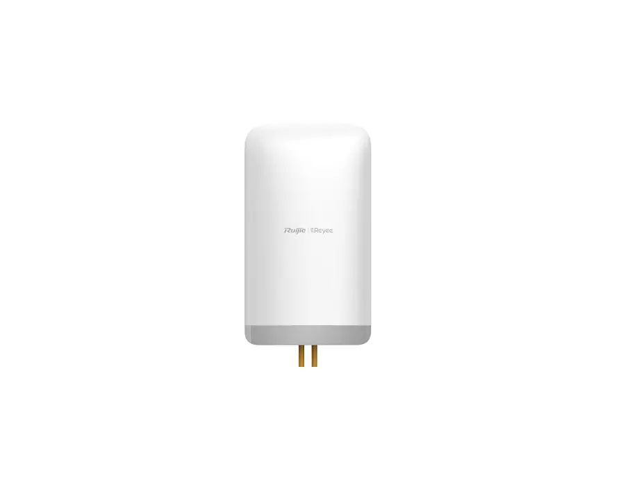
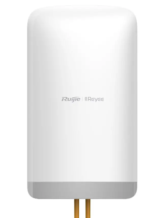
RG-EST350 provides 2 LAN ports (RJ-45 ports) and a 12 V DC port.
Figure 1-1 Top View of RG-EST350
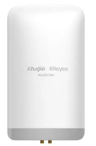
Figure 1-2 Bottom View of RG-EST350
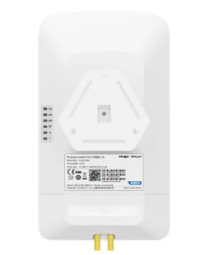
Ports
Figure 1-3 Ports
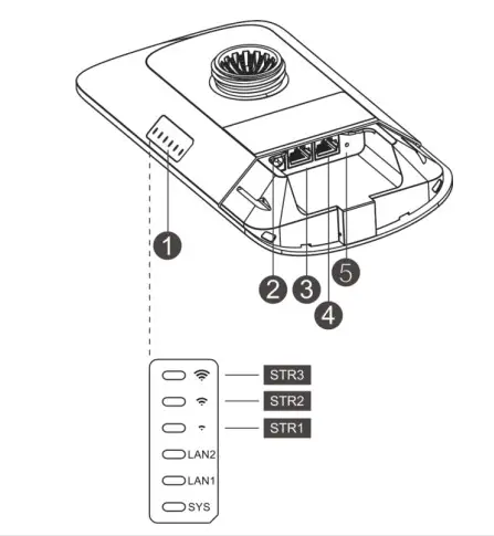
Note 1. LEDs
a. SYS LED
b. LAN1/LAN2 LED
c. Signal LED (STR1/STR2/STR3)
2. 12 V DC Port
3. LAN2 Port
4. LAN1/PoE Port
5. Reset Button
Power Supply
RG-EST350 adopts 24 V PoE or 12 V DC power supply (standard accessory: 24 V/0.5A PoE adapter).
Note Please do not use a PoE adapter or switch of another model. The device may be damaged.
2 Preparing for Installation
To prevent device damage and physical injury, please read the safety recommendations carefully as described in this chapter.Suggestions do not cover all possible hazardous situations
2.1 Lightning Protection
- When the connection cable between the main grounding conductor and local equipotential earthing terminal board (LEB) on each floor is shorter than 2 meters, use a stranded copper wire with a sectional area not less than 1.318 mm2 (16 AWG) for the connection cable.
- Use a shielded network cable if possible, ensure that devices connected to both ends of the shielded network cable are reliably grounded, and make sure that the sheath of the shielded network cable is also grounded if possible. If no shielded network cable is available, wire the network cable through a steel pipe and bury the steel pipe for lead-in, and properly ground both ends of the steel pipe.
- No additional lightning protector is required as a high-profile lightning protector is built in the RG-EST350 and the antenna port and power port support 4kV lightning protection. If a lightning protector of a higher profile is available, configure the lightning protector optionally. Before the configuration, connect the lightning protector to the ground cable.
2.2 Installation Site
- Do not expose the device to high temperature, dust, or harmful gases.
- Do not install the device in an area prone to fire or explosions.
- Keep the device away from EMI sources such as large radar stations, radio stations, and substations.
- Do not subject the device to unstable voltage, vibration, and noises.
- Keep the device at least 500 meters away from the ocean and do not face it towards the sea breeze.
- The installation site should be protected from water and flooding, seepage, dripping, or condensation.
- The installation site should be selected according to network planning, communications equipment features and considerations such as climate, hydrology, geology, earthquake, electric power, and transportation.
2.2.1 Temperature and Humidity
To ensure the normal operation and equipment service life, maintain appropriate temperature and humidity levels in the equipment room. See Table 2-1.
Table 2-1 Temperature and Humidity Requirement
| Working Temperature | -30°C to 65°C (-22°F to 149°F) |
| Working Humidity | 5% to 95% (non-condensing) |
2.2.2 Outdoor Installation
RG-EST350 supports wall mounting and pole mounting.
2.2.3 EMI
Various interference sources, from either outside or inside the device or application system, affect the system in the
conductive ways such as capacitive coupling, inductive coupling, and electromagnetic radiation. There are two types of electromagnetic interferences: radiated interference and conducted interference, depending on the type of the propagation path. When the energy, often RF energy, from a component arrives at a sensitive component via the space, the energy is known as radiated interference. The interference source can be either a part of the interfered system or a completely electrically isolated unit. Conducted interference results from the electromagnetic wire or signal cable connection between the source and the sensor. Interference along the cable the interference is transmitted from one unit to another. Conducted interference often affects the power supply of the device, but can be controlled by a filter. Radiated interference may affect any signal path in the device, and is difficult to shield.
- Effective measures should be taken for the power system to prevent electric grid interference.
- The working ground of the routers should be properly separated and kept as far as possible from the grounding device of the power device or the anti-lightning grounding device.
- Keep the device away from high-power radio transmitter, radar transmitting station, and high-frequency largecurrent device.
- Take electrostatic shielding measures.
2.3 Installation Tool
Table 2-2 Installation Tools
Tools.
Marker, Phillips (crosshead) screwdriver, slotted screwdriver, drill, paper knife, crimping pliers, diagonal pliers, wire stripper, network cable tester, related power and fiber cables, wrench, hammer, hose clamp, ESD tools, multimeter
2.4 Unpacking and Checking
Please check your goods carefully against the parts list. If you have any questions or there are any errors, please contact your distributor
3 Installing the Device
Before installing the device, make sure you have carefully read the requirements described in Chapter 2.
3.1 Installation Flowchart
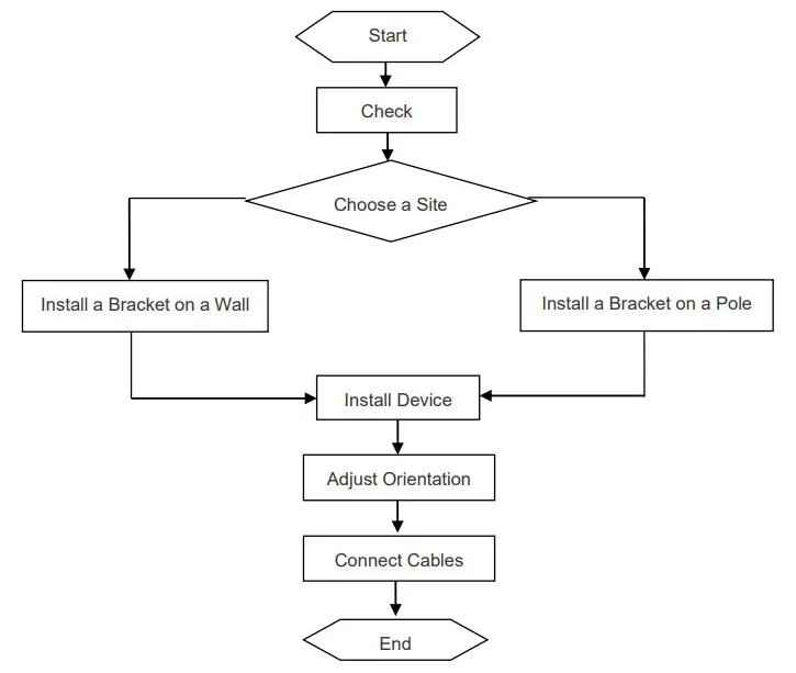
3.2 Before You Begin
Before you install the device, verify that all the parts in the parts list are there and make sure that:
- The installation site meets temperature and humidity requirements.
- The installation site is equipped with a proper power supply.
- Network cables are in place.
3.3 Precautions
The device can be mounted on a wall and a pole (diameter: 35 mm to 89 mm). If the diameter of the pole is out of the range, the hose clamp is customer-supplied. In this case, we strongly recommend you to use a hose clamp with thickness of 2.5mm at least. Otherwise, the device could fall down and cause injuries. When multiple bridges are installed at close range, in order to avoid interference between bridges, the horizontal distance between two bridges should be 2m and the vertical distance be 0.5m, or the horizontal angle of the two bridges should be greater than 120 degrees. The installation
site can vary due to on-the-spot surveys conducted by technical personnel.
Please make full preparations as described in Chapter 2 and observe the following precautions before installing the device.
- Before connecting the power supply, please use the PoE adapter shipped with the device or use a PoE adapter with the same specification.
- Before connecting the power cord, make sure the power switch is in the OFF position.
- Make sure the power supply is properly connected.
3.4 Installing Device
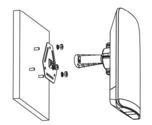
- Wall Mounting (connect the cable in advance)
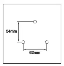
1. Secure the mounting bracket on the wall.
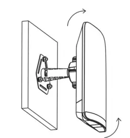
2. Install the device to the mounting bracket.
Figure 3-1 Wall Mounting
Drill holes into the marked positions and insert wall anchors. The head of the wall anchor should be at least 10 mm above the wall
Assemble the mounting kit.
Adjust the orientation. - Pole Mounting
- Secure the mounting bracket to the pole by threading a clamp through the mounting
- Install the device to the mounting
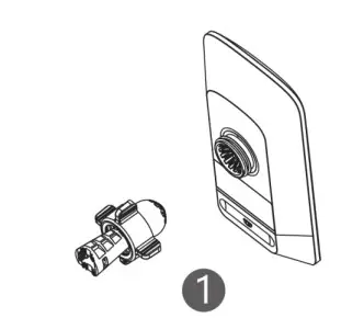
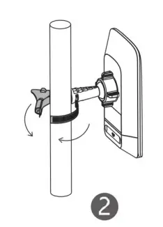
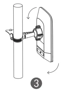
Figure 3-2 Pole Mounting
Assemble the mounting kit.
Secure the device on a pole by using a hose clamp
Adjust the orientation.
3.5 Connecting Cables
- Select a cable according to the distance between the wireless bridge and the PSE.
- Plug one end of the cable into the PoE port of the PoE adaptor, and plug the other end into the LAN1/PoE port of the device. Connect the LAN port of the PoE adaptor to the server or camera.
Figure 3-3 Recorder End Connection
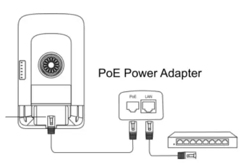
![]() Please install the rear cover for waterproof and dustproof purpose.
Please install the rear cover for waterproof and dustproof purpose.![]() Please do not use a PoE adapter or switch of another model. The device may be damaged.
Please do not use a PoE adapter or switch of another model. The device may be damaged.
Appendix A Connectors and Media
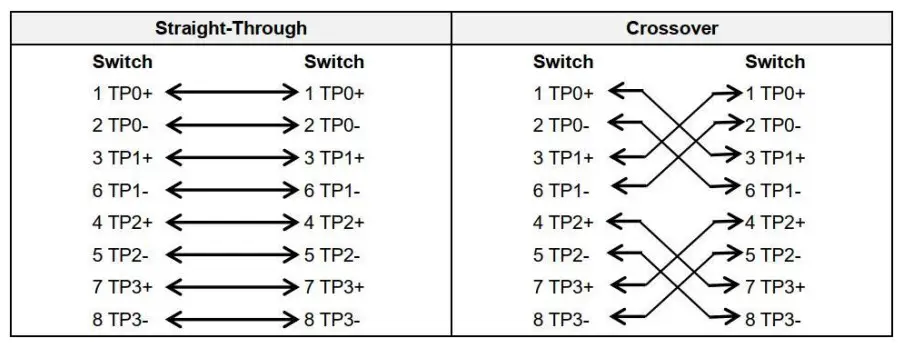
1000BASE-T/100BASE-TX/10BASE-T
The 1000BASE-T/100BASE-TX/10BASE-T is a 10/100/1000 Mbps auto-negotiation port that supports auto MDI/MDIX.
Compliant with IEEE 802.3ab, 1000BASE-T requires Category 5e 100-ohm UTP or STP (STP is recommended) with a maximum distance of 100 meters (328 feet).
1000BASE-T requires all four pairs of wires be connected for data transmission, as shown in Figure A-1.
Figure A-1 1000BASE-T Connection
10BASE-T uses Category 3, 4, 5 100-ohm UTP/STP and 1000BASE-T uses Category 5 100-ohm UTP/STP for connections. Both support a maximum length of 100 meters. Table A-1 shows 100BASE-TX/10BASE-T pin assignments.
Table A-2 100BASE-TX/10BASE-T Pin Assignments
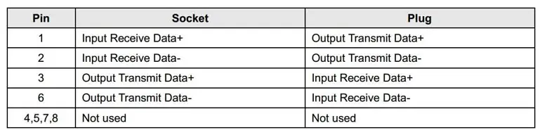
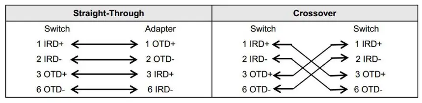
Figure A-3 shows wiring of straight-through and crossover cables for 100BASE-TX/10BASE-T.
Figure A-3 100BASE-TX/10BASE-T Connection
Appendix B Parts List
Table B-1 RG-EST350 Parts List
| No. | Part Description | Qty |
| 1 | RG-EST350 Recorder | 1 |
| 2 | RG-EST350 Camera | 1 |
| 3 | 24V/0.5A PoE Power Adapters | 2 |
| 4 | RG-EST350 Product Manual | 1 |
| 5 | Phillips Pan Head Screws | 8 |
| 6 | Wall Anchors | 6 |
| 7 | Universal Joint Assemblies | 2 |
| 8 | Mounting Brackets | 2 |
| 9 | Hose Clamps | 2 |
| 10 | Universal Joint Nuts | 2 |


