
HYLINTECH HLM5934 Series Gateway Module User Manual
Overview
HLMx93x series modules are developed based on the digital baseband chip SX1302 with a mechanical definition of the Mini PCIe interface and provide SPI interface.
HLMx93x series modules are developed based on the digital baseband chip SX1302 with a mechanical definition of the Mini PCIe interface and provide SPI interface.
Key Features
- Supportsmultiplebands
- SPI Interface
- (G)FSK demodulator
- High precision TCXO clock source
Typical Specification
- operating range from -40 to +85° C
- Power supply voltage range: 3.0V-3.6V
- Antenna interface: IPEX-1
Usage
- LoRa/LoRaWAN Gateway
- LoRa Network Analysis Tool
Model Information
| *Model | Tx Band | Max Power | Rx Band | LBT | MOQ |
| HLM7931 | 490-510MHz | 22dBm | 470-510MHz | Not Support | 3000 |
| HLM7932 | 470-510MHz | 22dBm | 470-510MHz | Support | 1000 |
| HLM9931 | 863-928MHz | 27dBm | 863-928MHz | Support | EOL |
| HLM9932 | 863-928MHz | 27dBm | 863-928MHz | Support | 1000 |
| HLM9933 | 902-928MHz | 28dBm | 902-928MHz | Support | 1000 |
| HLM8934 | 863-870MHz | 27dBm | 863-870MHz | Support | 1000 |
| HLM5934 | 902-928MHz | 27dBm | 902-928MHz | Support | 1000 |
| HLM9934 | TBD | 27dBm | TBD | Support | – |
| HLM8834 | TBD | 21dBm | TBD | Support | – |
| HLM5834 | TBD | 21dBm | TBD | Support | – |
| HLM9834 | TBD | 21dBm | TBD | Support | – |
| HLM9953 | TBD | 27dBm | TBD | Support | – |
*The full model number will contain the “-xxx” suffix to distinguish the packaging method, screen printing information, etc., such as HLM5934-P01.
Specifications
Table 2-1 Absolute Minimum and Maximum Ratings
| Name | Value | Description | ||
| Min | Max | Unit | ||
| Power Supply | -0.5 | +3.9 | V | |
| Storage temperature | -40 | +125 | ℃ | |
| Peak reflow temperature | – | 260 | ℃ | |
Table 2-2 Electrical Specifications
| Name | Value | Description | ||||
| Min | Typ | Max | Unit | |||
| Power Supply | 3.0 | 3.3 | 3.6 | V | The transmitting power decreases when the supply voltage is below 3.0V | |
| Operating temperature | -40 | – | 85 | ℃ | ||
| Frequency Stability | 2 | ppm | 25℃ | |||
| Tx Power* | HLM7931 | 20 | 21 | 22 | dBm | @490MHz~510MHz |
| HLM7932 | 20 | 21 | 22 | dBm | @470MHz~510MHz | |
| HLM9932 | 25 | 26 | 27 | dBm | @863MHz~928MHz | |
| HLM9933 | 20 | 24 | 28 | dBm | @902MHz~928MHz | |
| HLM8934 | 25 | 26 | 27 | dBm | @863MHz~870MHz | |
| HLM5934 | 23 | 25 | 27 | dBm | @902MHz~928MHz | |
| HLM9934 | dBm | TBD | ||||
| HLM8834 | dBm | TBD | ||||
| HLM5834 | dBm | TBD | ||||
| HLM9834 | dBm | TBD | ||||
| HLM9953 | dBm | TBD | ||||
| Rx Sensitivity** | HLM7931 | -127 | dBm | SF7BW125CR4/5@470MHz~510MHz | ||
| HLM7932 | -127 | dBm | SF7BW125CR4/5@470MHz~510MHz | |||
| HLM9932 | -127 | dBm | SF7BW125CR4/5@863MHz~928MHz | |||
| HLM9933 | -127 | dBm | SF7BW125CR4/5@863MHz~928MHz | |||
| HLM8934 | -125 | dBm | SF7BW125CR4/5@863MHz~870MHz | |||
| HLM5934 | -126 | dBm | SF7BW125CR4/5@902MHz~928MHz | |||
| HLM9934 | dBm | TBD | ||||
| HLM8834 | dBm | TBD | ||||
| HLM5834 | dBm | TBD | ||||
| HLM9834 | dBm | TBD | ||||
| HLM9953 | dBm | TBD | ||||
| Interface Packaging | Mini PCIe | |||||
| Digital Interface | SPI | – | ||||
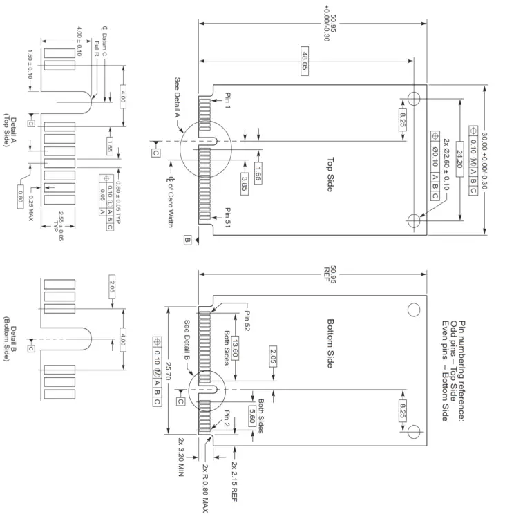
| Dimension (mm) | 30×50.95×3 | |||||
| CDimensional accuracy l W Test under nomina | temperatureGB/T1804-C conditions. and voltage | |||||
Package and Pin Connections
Package
Pin Connections
| Pin Number | Pin Name | Description | |
| 1 | NC | NC | |
| 2 | NC/5V | NC | |
| 3 | NC | NC | |
| 4 | GND | ||
| 5 | NC | NC | |
| 6 | GPIO[9] | SX1302’s GPIO[9] Pin | |
| 7 | NC | NC | |
| 8 | NC | NC | |
| 9 | GND | ||
| 10 | NC | NC | |
| 11 | NC | NC | |
| 12 | NC | NC | |
| 13 | NC | NC | |
| 14 | NC | NC | |
| 15 | GND | ||
| 16 | NC/Power_EN | HLM7931 | NC |
| Others | Power Enable Pin | ||
| 17 | SCK | SX1302 and SX126x’s SCK Pin | |
| 18 | GND | ||
| 19 | MISO | SX1302 and SX126x’s MISO Pin | |
| 20 | NC | NC | |
| 21 | GND | ||
| 22 | RESET | SX1302’s RESET Pin, High level reset | |
| 23 | MOSI | HLM7931 SX1302 and SX126x’s MOSI Pin | |
| 24 | NC/LBT_BUSY | NC | |
| Others | SX126x ‘s BUSY Pin | ||
| 25 | CSN | SX1302’s CSN Pin | |
| 26 | GND | ||
| 27 | GND | ||
| 28 | NC/LBT_DIO2 | HLM7931 | NC |
| Others | SX126x’s DIO2 Pin | ||
| 29 | GND | ||
| 30 | SCL | Temperature Sensor ,SSTS751 | |
| 31 | PPS | SX1302’s PPS Pin | |
| 32 | SDA | Temperature Sensor ,SSTS751 | |
| 33 | NC | NC | |
| 34 | GND | ||
| 35 | GND | ||
| 36 | NC | NC | |
| 37 | GND | ||
| 38 | NC | NC | |
| 39 | VCC | 3.3V Power | |
| 40 | GND | ||
| 41 | VCC | 3.3V Power | |
| 42 | NC | NC | |
| 43 | GND | ||
| 44 | NC/LBT_NSS | HLM7931 | NC |
| Others | SX126x’s NSS Pin | ||
| 45 | NC | HLM7931 NC NC | |
| 46 | NC/LBT_DIO1 | ||
| Others | SX126x’s DIO1 Pin | ||
| 47 | NC | HLM7931 NC NC | |
| 48 | NC/LBT_RST | ||
| Others | SX126x’s NRESET Pin, Low level reset | ||
| 49 | NC | NC | |
| 50 | GND | ||
| 51 | GPIO[4] | HLM7931 SX1302’s GPIO[4] Pin | |
| 52 | NC/VCC | NC | |
| Others | 3.3V Power | ||
Basic Usage
Application Circuit
When using this module, the main attention is paid to the handling of power ripple.HLM7 932,HLM9931, HLM9932, HLM9933, HLM5934, HLM8934’s Pin2 is NC.
Layout
- Try to give this module a separate power supply and ensure that the power ripple is as small as possible.
- If you use IPEX to connect to an external antenna, take care to consider the lightning protection design of the external antenna.
- Stay away from high voltage circuits, high frequency switching circuits.
SPI Timings
Users communicate with SX1302, the main chip of this module, through SPI interface, and achieve control and access to SX1302 by accessing SX1302 registers. For specific usage, you can refer to the SX1302 information released by SEMTECH official website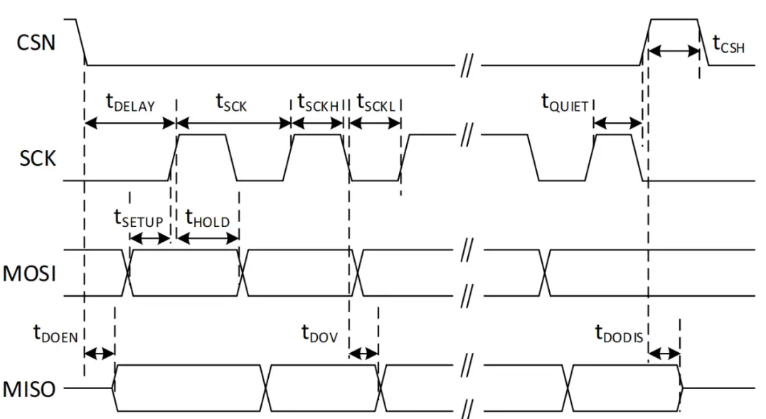
Revisions
| Version | Date | Author | Description |
| 1.0 | 2021-06-18 | Hylintech | Initial Version |
| 1.01 | 2021-07-13 | Hylintech | Modify interface |
| 1.11 | 2021-09-08 | Hylintech | Modify interface |
| 1.2 | 2021-10-24 | Hylintech | Modify interface |
| 1.21 | 2021-11-03 | Hylintech | Add reset Pin description |
| 1.22 | 2021-11-16 | Hylintech | HLM9931 EOL |
| 1.3 | 2022-01-06 | Hylintech | Adding new models |
FCC Statement
Any Changes or modifications not expressly approved by the party responsible for compliance could void the user’ s authority to operate the equipment.
This device complies with part 15 of the FCC Rules. Operation is subject to the following two conditions:
- This device may not cause harmful interference, and
- This device must accept any interference received, including interference that may cause undesired operation.
Note: This equipment has been tested and found to comply with the limits for a Class B digital device, pursuant to part 15 of the FCC Rules. These limits are designed to provide reasonable protection against harmful interference in a residential installation. This equipment generates, uses and can radiate radio frequency energy and, if not installed and used in accordance with the instructions, may cause harmful interference to radio communications. However, there is no guarantee that interference will not occur in a particular installation. If this equipment does cause harmful interference to radio or television reception, which can be determined by turning the equipment off and on, the user is encouraged to try to correct the interference by one or more of the following measures:
- Reorient or relocate the receiving antenna.
- Increase the separation between the equipment and receiver.
- Connect the equipment into an outlet on a circuit different from that to which the receiver is connected.
- Consult the dealer or an experienced radio/TV technician for help
RF Exposure Statement
This equipment complies with FCC radiation exposure limits set forth for an uncontrolled environment. This equipment should be installed and operated with minimum distance 20cm between the radiator and your body.
FCC Label Instructions
If using a permanently affixed label, the modular transmitter must be labeled with its own FCC identification number, and, if the FCC identification number is not visible when the module is installed inside another device, then the outside of the device into which the module is installed must also display a label referring to the enclosed module. This exterior label can use wording such as the following:
“Contains FCC ID: 2A4G5-HLM5934”.
Any similar wording that expresses the same meaning may be used. The Grantee may either provide such a label, an example of which must be included in the application for equipment authorization, or, must provide adequate instructions along with the module which explain this requirement.
OEM Guidance
- Applicable FCC rules
OEM Guidance This device complies with part 15.247 of the FCC Rules. - The specific operational use conditions This module can be used in IoT devices. The input voltage to the module is nominally 3.3 V DC. The operational ambient temperature of the module is -40 °C ~ 85 °C. the external antenna is allowed, such as monopole antenna.
- Limited module procedures
N/A - Trace antenna design
N/A - RF exposure considerations
The equipment complies with FCC radiation exposure limits set forth for an uncontrolled environment. This equipment should be installed and operated with minimum distance 20cm between the radiator and your body. If the equipment built into a host as a portable usage, the additional RF exposure evaluation may be required as specified by 2.1093. - Antenna
Antenna type: Monopole antenna; Peak antenna gain: 2 dBi - Label and compliance information
An exterior label on OEM’s end product can use wording such as the following: “Contains Transmitter Module FCC ID: 2A4G5 HLM5934” or “Contains FCC ID: 2A4G5-HLM5934” - Information on test modes and additional testing requirements
The modular transmitter has been fully tested by the module grantee on the required number of channels,modulation types, and modes, it should not be necessary for the host installer to re-test all the available transmitter modes or settings. It is recommended that the host product manufacturer, installing the modular transmitter,perform some investigative measurements to confirm that the resulting composite system does not exceed the spurious emissions limits or band edge limits (e.g., where a different antenna may be causing additional emissions).
The testing should check for emissions that may occur due to the intermixing of emissions with the other transmitters, digital circuitry, or due to physical properties of the host product (enclosure). This investigation is especially important when integrating multiple modular transmitters where the certification is based on testing each of them in a standalone configuration. It is important to note that host product manufacturers should not assume that because the modular transmitter is certified that they do not have any responsibility for final product compliance.
If the investigation indicates a compliance concern the host product manufacturer is obligated to mitigate the issue. Host products using a modular transmitter are subject to all the applicable individual technical rules as well as to the general conditions of operation in Sections 15.5, 15.15, and 15.29 to not cause interference. The operator of the host product will be obligated to stop operating the device until the interference have been corrected. - Additional testing, Part 15 Sub part B disclaimer The final host / module combination need to be evaluated against the FCC Part 15B criteria for unintentional radiators in orderto be properly authorized for operation as a Part 15 digital device.
The host integrator installing this module into their product must ensure that the final composite product complies with the FCC requirements by a technical assessment or evaluation to the FCC rules, including the transmitter operation and should refer to guidance in KDB 996369. For host products with certified modular transmitter, the frequency range of investigation of the composite system is specified by rule in Sections 15.33(a)(1) through (a)(3), or the range applicable to the digital device, as shown in Section 15.33(b)(1), whichever is the higher frequency range of investigation When testing the host product, all the transmitters must be operating. The transmitters can be enabled by using publicly-available drivers and turned on, so the transmitters are active. In certain conditions it might be appropriate to use a technology specific call box (test set) where accessory 50 devices or drivers are not available. When testing for emissions from the unintentional radiator, the transmitter shall be placed in the receive mode or idle mode, if possible. If receive mode only is not possible then, the radio shall be passive (preferred) and/or active scanning. In these cases, this would need to enable activity on the communication BUS (i.e., PCIe, SDIO, USB) to ensure the unintentional radiator circuitry is enabled. Testing laboratories may need to add attenuation or filters depending on the signal strength of any active beacons (if applicable) from the enabled radio(s). See ANSI C63.4, ANSI C63.10 and ANSI C63.26 for further general testing details. The product under test is set into a link/association with a partnering device, as per the normal intended use of the product. To ease testing, the product under test is set to transmit at a high duty cycle, such as by sending a file or streaming some media content.