PAD-GCADMH Desk Grommet Mount
Desk Grommet Mount
with Non-Security Universal Holder
PAD-GCADMH
INSTRUCTION – MANUAL
Package Contents:
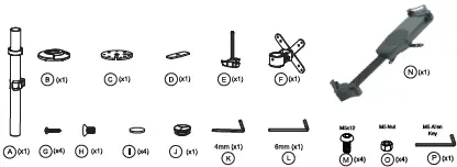
Instructions:
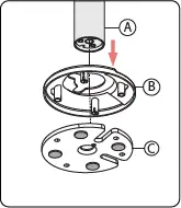
1. Setting Components for Mounting
![]()
1A. Take the body pole endcap (J) and place it on the top end of the
body pole (A) as illustrated above.
1B. Take the top half of the grommet clamp (C) and place on the (4)
pads (I) underneath as shown. Peel off the sticker backing, and with
the adhesive side facing the clamp, place it on securely.
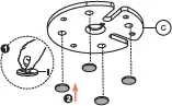
2. Setting Up Grommet Clamp Mount Installation
2A. Align the bottom end of the body pole
(A) with the canopy (B) and with the top
piece of the clamp (C).
2B. Using a power drill tool (not included), drill a 10mm diameter hole through the surface you wish to mount into. Take the knob screw component (E) and the bottom piece of the clamp (D) from below and align with the top side components from step 2A. Then rotate the knob with bottom piece until securely tightened.
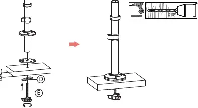
3. Setting Up Direct Grommet Mount Installation
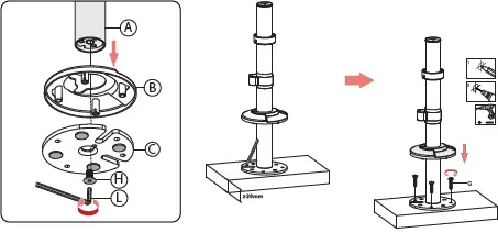
3A. Align the bottom end of the body pole (A) with the canopy (B) and with the top piece of the clamp (C). Then rotate in screw (H) from below using provided tool (L) until securely tightened as illustrated above.
![]()
 3B.Take the assembled body commination and place it on the surface top. Lift up the canopy to see drill holes. Then drill in (4) screws in the screw holes until securely tightened with screwdriver or power drill. (Both not provided). Slide canopy back down over the top clamp piece.
4. Placing VESA Mount on Pole
4A. Using the provided tool (K), loosen the
stopper component on the body pole to raise or
lower until desired height. This will prevent any
other components from sliding down. Once
desired height is set, tighten stopper component
with tool until securely fastened.
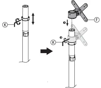 4B. Take VESA mount pole
mount (F) and slide it from
above onto the body pole
(A). Slide it down until it
rests on the stopper. Take
the provided tool (K) and
tighten as illustrated until
securely fastened.
5. Connect VESA w/ Non-Security Holder
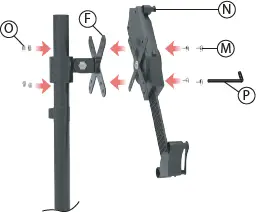
5A. Align clamp mount VESA plate (F) with the VESA plate of the
tablet holder (N). Then using the provided tool (P), rotate in
screws (M) from the front while holding the hex nuts (O) from
behind with your hand. Do this for all (4) screws until securely
tightened.
6. Adjusting VESA Joint for Tilt, Swivel & Orientation Adjustability
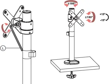
6A. Align clamp mount VESA plate (F) with the VESA plate of the tablet holder (N). Then using the provided tool (P), rotate in screws (M) from the front while holding the hex nuts (O) from behind with your hand. Do this for all (4) screws until securely tightened.
7. Cable Routing & Tool Management
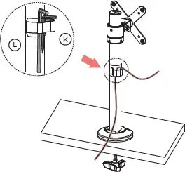
7A.Identify cable management clip / tool organizer on the body pole
(A). When fishing your wire from the tablet/device towards the power
source, hook onto the clip to aid in neatly routing the cable. Also on
the side of the clip, you can find two tool holders to help put away
provided tools (L, K) as illustrated above. When angle adjustments
are needed and joints need to be loosened, it provides quick access
to the needed tools.


