nilfisk food S Booster MP44 Topax Hygiene System User Guide

1. Preface
The S Booster is designed for the boosting and transfer of clean water to cleaning equipment within the food industry.
It is important that your operational staff reads these directions for use prior to the installation and start of operation. Operation as laid down in these directions for use will ensure an optimum level of hygiene in your factory and a minimum level of maintenance and repair work.
1.0 Application
The S Booster is made of corrosion resistant materials, mainly stainless steel, and is therefore, especially suitable for application within the food industry. If you need
information on further applications, please contact Ecolab.
1.1 Warnings
The special warnings CAUTION, ATTENTION and NOTE used in this Technical
Manual have the following meanings:
CAUTION: This term is used to highlight the fact that complete or even partial failure to properly adhere to operating instructions, working instructions, specified working sequences and similar can cause
personal injuries or accidents.
ATTENTION: This term is used to highlight the fact that complete or even partialfailure to properly adhere to operating instructions, working instructions, specified working sequences and similar can cause damage to the equipment.
NOTE: This term is used to draw attention to a particular feature.
1.2 Safety Instructions
A) Repairs are only to be carried out when the unit is switched off.
 Warning!
 Warning!
The unit is only to be used for purposes as described in this user guide.
Dry running for even a very short period of time can cause dry running not detected by our dry running security. In any case a stable and sufficient water supply is ALWAYS required.
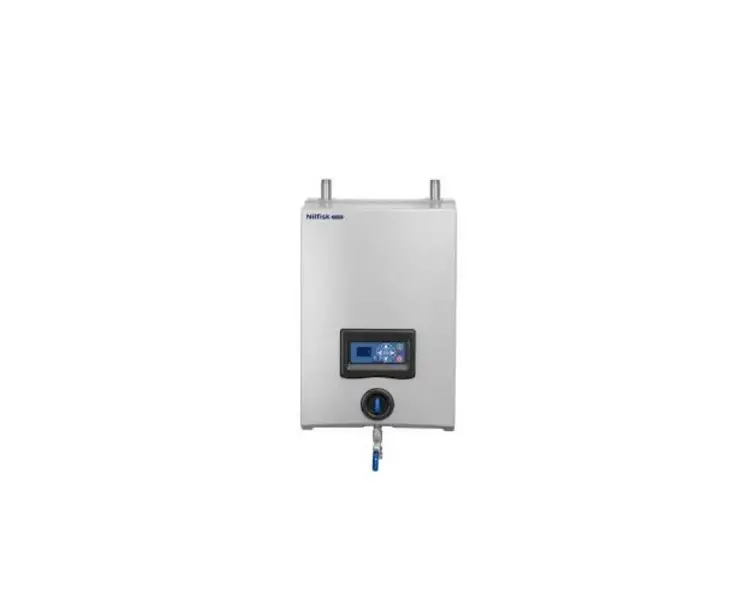
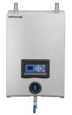
2. Standard Unit
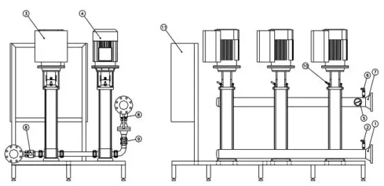
The Booster consists of two pumps mounted on a floor frame, non-return valves, manifold (inlet) with flow switch, manifold (outlet) and Booster controller unit.
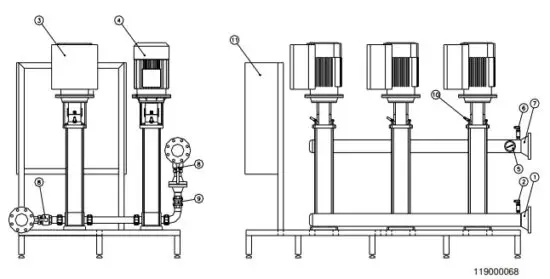
- Inlet 6. Manifold
- Manifold 7. Outlet
- CRIE Pump 8. Ball valve
- SF Pump 9. Non return valve
- Pressure transmitter 10. Temperature sensor
- MPC-E controller
3. Description of Function
3.0 Flow Chart
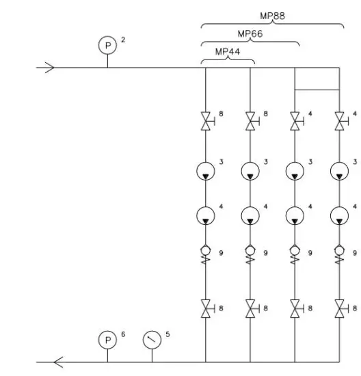
- Pressure transmitter
- Pressure transmitter
- CRIE Pump
- Ball valve
- SF Pump
- Non return valve
- Pressure gauge
4. Installation
4.0 General
The Booster unit must be installed and all electric connections must be performed in accordance with local regulations.
4.1 Mounting
The Booster unit must be placed in a well ventilated room, in order to secure adequate air supply for cooling of the pump engines. This also applies when the motors are in operation.
The clearance in front of and on either side of the pumps must be at least 75cm.
4.2 Pipe Work
When installing the piping take care to avoid air traps.
CAUTION
Before the booster unit is connected to the water supply, the supply line should be rinsed through carefully in order to remove coarse impurities and metal shavings.
The pipes are connected to the manifolds of the Booster set. Either end can be used.
The set must be tightened up before start-up.
4.3 Priming
Do not start the pumps until filled with water!
4.4 Electric connection
Electrical connections must be carried out in accordance with local regulations and must only be carried out by authorised engineers.
The motors are started directly on line (Star delta, optional).
The motors are fitted with built in thermal switches.
As additional protection, fault voltage relays, earthing or neutralising can be used instead.
The wiring diagram is placed on the inside of the S Booster control unit. The diagrams state values required for the electricity supply.
 NOTICE
 NOTICE
Check direction of rotation.
The correct direction of rotation is shown by arrows on the pump head and on the motor fan cover
5. Function
5.0 Operational Instructions
5.1 Operation of Booster controller
Please see MPC User guide
6. Technical Data
| Data | MP44 | MP66 | MP88 |
| Siehe | Siehe | Siehe | |
| Supply voltage | Typenschilder auf | Typenschilder auf | Typenschilder auf |
| Motoren | Motoren | Motoren | |
| Isolation class | IP54 | IP54 | IP54 |
| Max. Leistungsverbrauch | 60 kW | 90 kW | 120 kW |
| Control voltage | 24 VAC | 24 VAC | 24 VAC |
| Capacity | 0-44m3/h | 0-66m3/h | 0-88m3/h |
| Water inlet pressure | 2-4 bar | 2-4 bar | 2-4 bar |
| Water inlet volume | Min. 44 m3/h | Min. 66 m3/h | Min. 88 m3/h |
| Water inlet temperature | Max. 70°C | Max. 70°C | Max 70°C |
| Temperature | 5-40°C | 5-40°C | 5-40°C |
| Capacity: | |||
| The figures show the max | |||
| m3/h (l/min) the pumps | |||
| can deliver at an inlet | |||
| pressure of 2 bar and | |||
| following end pressures | |||
| 30 bar: 35 bar: 40 bar | 44,8 (753) 39,6 (660) 33,0 (550) | 67,2 (1130) 59,4 (990) 49,5 (825) | 89,6 (1506) 79,2 (1320) 66,0 (1100) |
| Approvals: | CE | CE | CE |
| Weight: | 1400 kg | 1750 kg | 2800 kg |
| Dimensions (H x B x T): | 2000 x 1500 x 1800 | 2000 x 1500 x 2500 | 2000 x 1500 x 3200 |
| mm | mm | mm |
7. Maintenance
7.0 Instructions
Depending on usage, maintenance should be undertaken by an authorised service engineer at least once a year in order to prevent defects and failure of operation.
Authorised engineers are persons who, due to their skills and experience, have sufficient knowledge of low pressure cleaning systems or similar and are confident with the state work safety regulations, accident preventive regulations, guidelines and generally acknowledged technical regulations such as DIN-norms and VDE-provisions.
For your safety, this cleaning system has been manufactured according to all relevant regulations valid within the EU and it has, therefore, been supplied with the CE-mark.
For further information, please contact the service department of Ecolab..
7.1 Trouble shooting and Remedy
Please see user guide for MPC.
8. Components
8.0 Exploded Drawing Booster MP Unit with Spare Spart List
| Pos. no. | Article no. | Description | Number |
| 1 | Inlet | 1 | |
| 2 | 313800 | Pressure transmitter | 1 |
| 3 | 0604221 | CRIE 15-17 Pump | 2 (3) (4) |
| 4 | 852900 | CRN 15-16SF Pump | 2 (3) (4) |
| 5 | 659000 | Manometer 0-60 Bar | 1 |
| 6 | 313800 | Pressure transmitter | 1 |
| 7 | Outlet | 1 | |
| 8 | 334604 | Ball valve | 4 (6) (8) |
| 9 | 359944 | Non return valve | 2 (3) (4) |
| 10 | 0601444 | Temperature sensor | 4 (6) (8) |
| 11 | 110001327 | Controller | 1 |
9. Warranty
Attention!
Our guarantee is given for a period of 12 months from delivery on all parts which have provable become unfit for use due to material, construction or manufacturing defects as well as inadequate work. The guarantee compensation will occur in the shape of either reimbursement, replacement or repair of the defective or damaged part at our works.
Installation and freight costs are always on the purchaser’s account. Any defective parts are to be placed at our disposal. Claims that may otherwise be raised for any legal reason will not be acknowledged. No liability will be accepted for damage occurred indirectly. The purchaser has no right to let any third party repair possible defects on our account.
All hoses, rubber parts or synthetic materials, natural wear and tear as well as damage caused by careless and inappropriate handling, including transport damage are not covered by the guarantee. Further, the guarantee does not apply if the system has been subjected to frost. The obligation of guarantee compensation also ceases if changes or repairs are made by non-authorised persons. Claims under the guarantee will only be acknowledged when they are placed immediately after the defect has been noticed. The guarantee ceases in case of change of ownership.
The dealer cannot be held responsible for personal injury, damage to equipment, working deficits, including production loss, loss of profits, loss of stock or the like which may occur by imperfect and delayed delivery of the sold product, regardless of the reason. Further, see our standard terms of sale and delivery..
CE Declaration of Conformity
Nilfisk-ALTO Food Division declares that the machine:
No.: 119000149
Name: Booster MP44
Type: Booster, MP
– is manufactured in conformity with the following standards:
Directive 2006/42/CE of the European Parliament and of the Council of 22 June 1998 on the approximation of the laws of the Member States relating to machinery.
EN 60335-2-79 Household and similar electrical appliances – Safety
Particular requirements for high pressure cleaners and steam cleaners EN 60335-2-34Household and similar electrical appliances – Safety
Particular requirements for motor-compressors
Council Directive 2004/108/CE of 3 May 1989 on the approximation of the laws of the Member States relating to Electromagnetic Compatibility.
Member States relating to Electromagnetic Compatibility.
EN 55014-1 Electromagnetic compatibility
EN 55014-2 Electromagnetic compatibility
EN 61000-2-3 Electromagnetic compatibility
EN 61000-3-3 Electromagnetic compatibility


