C12200 Mueller Streamline Installation Guide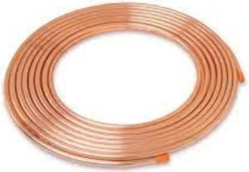
Product Description
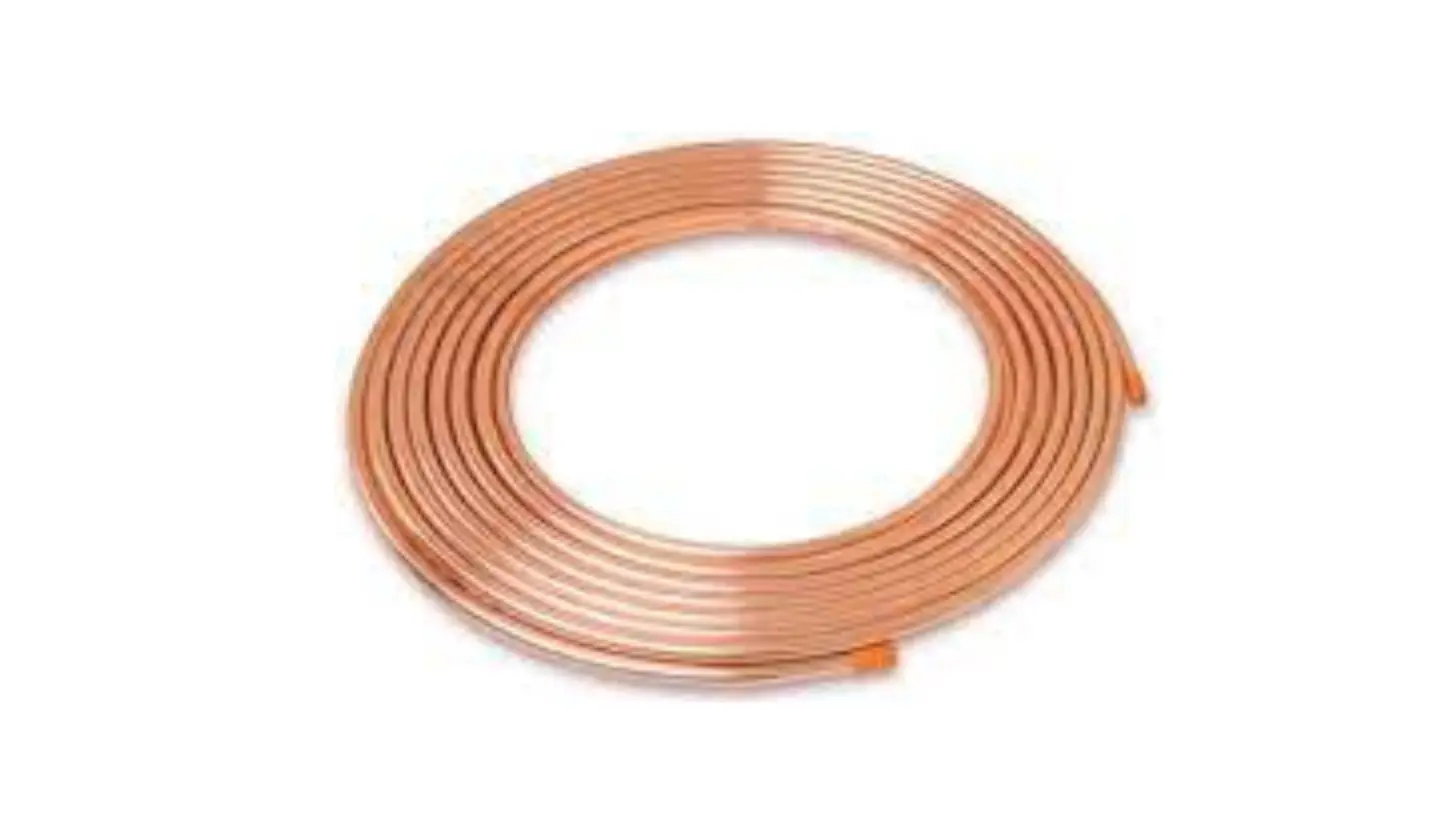
Streamline® Copper Tube for use in plumbing and mechanical applications. Available sizes (Type K, L, M, & DWV) ranging from ¼” to 8” in diameter. All tube shall be manufactured in the United States.
Material
Streamline® Copper Tube is manufactured from UNS C12200 grade of copper.
Key Specifications
Streamline® Copper Tube (Type K, L, M) shall conform to thev NSF/ANSI/CAN 61 Annex G requirements and is manufactured to meet ASTM B88. Copper drainage tube (DWV) is made to meet ASTM B306. Copper refrigeration coils, ACR/Nitrogenized straight lengths and line sets are made to meet the chemical, mechanical, cleanness and eddy current testing requirements of the applicable specifications of ASTM B280. Coils are manufactured to 060 temper, and straight lengths are manufactured to H58 temper.
Installation
Installations shall comply with the latest applicable building codes for the local jurisdiction. For detailed installation instructions, consult the Copper Developement Association at copper.org
References
C12200 99.9% Pure Copper (can be used for potable water)
NSF/ANSI/CAN 61 Annex G Safe Drinking Water Act (third party certification)
ASTM BBB Seamless Copper Water and Gas Tube (Type K, L, M)
ASTM B306 Seamless Copper Tube for Air Conditioning and Refrigerants
ASTM B306 Seamless Drainage Tube Code (DWV)
NSF/ANSI/372 Safe Drinking Water (Lead Content)
Copper [tube or fitting] UNS C12000 has been evaluated by NSF International to NSF/ANSI/CAN 61 for use in drinking water supplies of pH 6.5 and above. Drinking water supplies that are less than pH 6.5 may require corrosion control to limit leaching of copper into the drinking water.
COPPER TUBE DATA
Streamline® Copper Tube sets the standard for quality, consistency and service in the plumbing industries. With a full line of copper tube products to support most all plumbing supply and DWV applications, Streamline® Copper Tube is available in all common types including Type K, Type L, Type M and DWV. Each piece of tube is incised marked and color coded for easy, long lasting identity. Manufactured in accordance with applicable standards, our ongoing commitment to quality continues to make Streamline® Copper Tube the preferred and specified brand of industry professionals.
| TYPE K | RATED WORKING PRESSURE (PSIG) NOM. DIA. WT/FT FT/BNDL 150°F 200°F | |||||
| NOM. DIA. | WT/FT | FT/BNDL | 150°F | 200°F | 300°F | 400°F |
| 1/4 | 0.145 | 500 | 913 | 860 | 842 | 537 |
| 3/8 | 0.269 | 500 | 960 | 904 | 885 | 565 |
| 1/2 | 0.344 | 500 | 758 | 713 | 698 | 446 |
| 5/8 | 0.418 | 200 | 626 | 589 | 577 | 368 |
| 3/4 | 0.641 | 200 | 724 | 682 | 668 | 426 |
| 1 | 0.839 | 100 | 557 | 524 | 513 | 327 |
| 1 1/4 | 1.04 | 100 | 452 | 425 | 416 | 266 |
| 1 1/2 | 1.36 | 100 | 420 | 396 | 387 | 247 |
| 2 | 2.06 | – | 370 | 348 | 341 | 217 |
| 2 1/2 | 2.93 | – | 338 | 319 | 312 | 199 |
| 3 | 4.00 | – | 328 | 308 | 302 | 193 |
| 3 1/2 | 5.12 | – | 311 | 293 | 286 | 183 |
| 4 | 6.51 | – | 306 | 288 | 282 | 180 |
| 5 | 9.67 | – | 293 | 276 | 270 | 172 |
| 6 | 13.90 | – | 295 | 277 | 271 | 173 |
| 8 | 25.90 | – | 314 | 295 | 289 | 184 |
TYPE L
| 1/4 | 0.126 | 500 | 775 | 729 | 714 | 456 |
| 3/8 | 0.198 | 500 | 662 | 623 | 610 | 389 |
| 1/2 | 0.285 | 500 | 613 | 577 | 565 | 361 |
| 5/8 | 0.362 | 200 | 537 | 505 | 495 | 316 |
| 3/4 | 0.455 | 200 | 495 | 466 | 456 | 291 |
| 1 | 0.655 | 100 | 420 | 395 | 387 | 247 |
| 1 1/4 | 0.884 | 100 | 373 | 351 | 344 | 219 |
| 1 1/2 | 1.14 | 100 | 347 | 327 | 320 | 204 |
| 2 | 1.75 | – | 309 | 291 | 285 | 182 |
| 2 1/2 | 2.48 | – | 285 | 269 | 263 | 168 |
| 3 | 3.33 | – | 270 | 254 | 248 | 159 |
| 3 1/2 | 4.29 | – | 258 | 243 | 238 | 152 |
| 4 | 5.38 | – | 249 | 235 | 230 | 147 |
| 5 | 7.61 | – | 229 | 215 | 211 | 135 |
| 6 | 10.2 | – | 213 | 201 | 196 | 125 |
| 8 | 19.3 | – | 230 | 216 | 212 | 135 |
Tables give computed allowable stress for annealed copper tube at indicated temperature to provide worst case scenario. System designer should account for fitting and joining methodology to determine actual system ratings.
| TYPE M | RATED WORKING PRESSURE (PSIG) NOM. DIA. WT/FT FT/BNDL 150°F 200°F | |||||
| NOM. DIA. | WT/FT | FT/BNDL | 150°F | 200°F | 300°F | 400°F |
| 3/8 | 0.145 | 500 | 485 | 456 | 447 | 285 |
| 1/2 | 0.204 | 500 | 420 | 395 | 387 | 247 |
| 3/4 | 0.328 | 200 | 346 | 326 | 319 | 204 |
| 1 | 0.465 | 100 | 286 | 270 | 264 | 169 |
| 1 1/4 | 0.682 | 100 | 287 | 271 | 265 | 169 |
| 1 1/2 | 0.94 | 100 | 282 | 265 | 259 | 166 |
| 2 | 1.46 | – | 254 | 239 | 234 | 149 |
| 2 1/2 | 2.03 | – | 233 | 219 | 215 | 137 |
| 3 | 2.68 | – | 215 | 203 | 199 | 127 |
| 3 1/2 | 3.58 | – | 214 | 202 | 197 | 126 |
| 4 | 4.66 | – | 213 | 201 | 197 | 126 |
| 5 | 6.66 | – | 198 | 186 | 182 | 116 |
| 6 | 8.92 | – | 186 | 175 | 171 | 109 |
| 8 | 16.5 | – | 195 | 183 | 180 | 115 |
TYPE DWV
| NOM. DIA | WT/FT | FT/BNDL | 150°F | 200°F | 300°F | 400°F |
| 1 1/4 | 0.65 | 100 | 280 | 269 | 258 | 165 |
| 1 1/2 | 0.809 | 100 | 249 | 240 | 230 | 147 |
| 2 | 1.07 | – | 185 | 178 | 170 | 109 |
| 3 | 1.69 | – | 135 | 130 | 125 | 80 |
| 4 | 2.87 | – | 127 | 122 | 117 | 75 |
| 5 | 4.43 | – | 129 | 124 | 119 | 76 |
| 6 | 6.1 | – | 126 | 121 | 116 | 74 |
| 8 | 10.6 | – | 124 | 119 | 114 | 73 |
Table give computed allowable stress for annealed copper tube at indicated temperature to provide designers for worst case scenario. System designer should account for fitting and joining methodology to determine actual system ratings.
TECHNICAL DATA
Values of allowable internal working pressure for copper tube in service are based on the formula from ANSI B31, Standard Code for Pressure Piping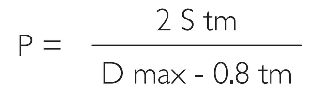
P = Allowable Pressure @150ºF S = 5100 PSIG annealed
S = Allowable stress @ 200°F S= 4800PSIG annealed
T = Wall thickness @ 300°F S= 4700 PSIG annealed
D Max = Outside Diameter @ 400°F S= 3000 PSIG annealed
All ratings listed for types K, L, M, DWV and refrigeration service tube in the preceding charts are calculated for tube in the annealed condition. These values should be used when soldering, brazing or welding is employed for joining components in a system. While the ratings for hard drawn tube are substantially higher, they should only be used for systems using properly designed flare or compression mechanical joints, since joining by any heating process might anneal (soften) the tube.
COPPER TUBE AND SOLDER TYPE FITTINGS
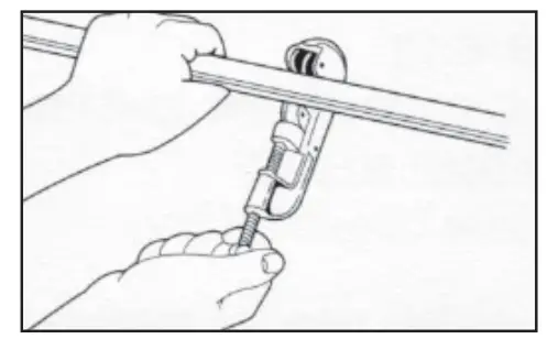
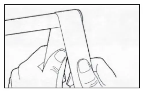
- Cut tube square with the cutter or fine hack saw (32 tooth blade is recommended). Remove Burr
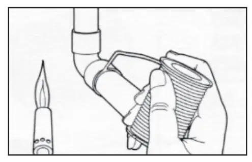
- Clean outside end of copper tube thoroughly with sand cloth or sandpaper equal depth of fitting. Leave no dark spots
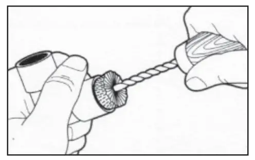
- Clean inside of fitting carefully to tube stop with wire brush. Note: Sand cloth or sandpaper may also be used.
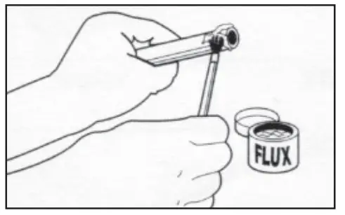
- Using a brush, apply light uniform coat of soldering flux to the outside of the tube and inside of the fitting.
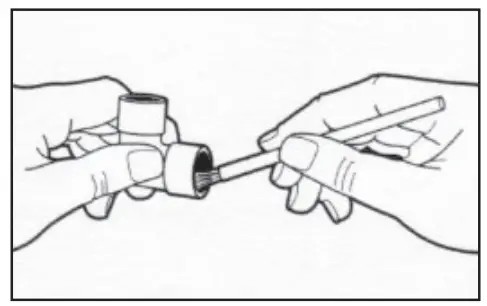
- Slip tube into fitting to tube stop. Turn tube back and forth once or twice to distribute flux evenly
- Apply heat uniformly around the fitting with torch. When solder melts upon contact with heated fitting, the proper soldering temperature has been reached. Remove flame and feed solder slightly off center at the bottom of the joint. Proceed across the bottom of the fitting and up to the top center position. Return to the starting point, and then proceed up the incomplete side to the top, again, overlapping the solder metal. Wipe off surplus solder with a piece of cloth.
CAUTION: No not overheat the joint or direct the flame into the face of the fitting cup. Overheating could burn the flux, which will destroy its effectiveness and the solder will not enter the joint properly
- Cut tube to length & remove burr with file or scrap

- Clean outside of tube with sandpaper or sand cloth.

- Clean inside of fitting with wire brush, sand cloth or sandpaper

- Apply flux thoroughly to inside of fitting

- Apply flux thoroughly to outside of tube – assemble tube and fitting

- Apply heat with torch. When solder melts upon contact with heated fitting, the proper temp for soldering has been reached. Remove flame & feed solder to the joint at one or two points until a ring of solder appears at the end of the fitting.

Job Name
Job Location
Engineer
Contractor
Wholesaler
Streamline® Rep
Distributed by Mueller Streamline Co.
150 Schilling Blvd., Suite 201, Collierville, TN 38017
800-348-8464
www.muellerstreamline.com
April 2022
![]() A BRAND OF MUELLER INDUSTRIES
A BRAND OF MUELLER INDUSTRIES
MADE IN USA