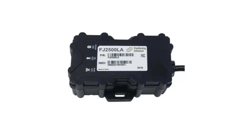
![]() FJ2500LA-12D Professional Grade Sealed Asset Monitor
FJ2500LA-12D Professional Grade Sealed Asset Monitor
Instruction Manual
Overview
The FJ2500 is a professional grade sealed asset monitoring product with an environmentally sealed enclosure able to withstand extreme conditions. The FJ2500 withstands high-pressure sprays, has a wide voltage and temperature operating range, ultra-low sleep power modes, hosts robust input and output capabilities, a rechargeable 1-year battery and vehicle Control Area Network (CAN) interfaces. Along with a Bluetooth radio, the FJ2500 creates a leading set of capabilities for even the most advanced applications.
The target applications for the platform include:
- Semi-Trailer Tracking
- Outdoor generators
- Single axle single purpose trailers
- Heavy duty construction equipment tracking
Installation
The installation of the FJ2500 could have a major impact on device performance. Care should be given to physical placement of the device as well as the connections made during installation. This guide covers the standard installation using an in-cab location with a J1939 connection to the vehicle data link.![]() The FJ2500LA-12D and FJ2500MG-12D currently support SAE J1939 and SAE J1708 heavy duty protocols, as well as SAE J1979 OBDII light duty protocol.
The FJ2500LA-12D and FJ2500MG-12D currently support SAE J1939 and SAE J1708 heavy duty protocols, as well as SAE J1979 OBDII light duty protocol.
Plan the installation:
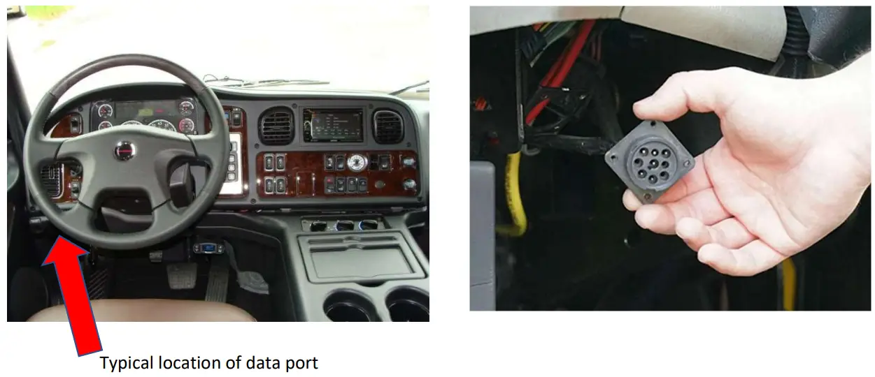
Locate the vehicle data link connector location used to interface with the ECU for your vehicle. If needed, ensure you have the correct adapter cable for your vehicle to connect to the native Deutsch harness that comes standard with the device.![]() The FJ2500LA-12D and FJ2500MG-12D come standard with a Deutsch DTM06-12sa harness, which will plug into the Deutsch DTM04-12p housing. Adapters for J1939, OBDII, or other Deutsch variants are available upon request.
The FJ2500LA-12D and FJ2500MG-12D come standard with a Deutsch DTM06-12sa harness, which will plug into the Deutsch DTM04-12p housing. Adapters for J1939, OBDII, or other Deutsch variants are available upon request.
The vehicle data link, or the J1939 connector is often found under the dashboard to the left of the steering column as indicated here:
Connect Device to Vehicle Diagnostics Port:
When installed with a J1939 adapter harness, the device will obtain power and ground from the vehicle’s diagnostic connector and provide a clandestine installation in the vehicle.
- Disconnect the OEM J1939 connector from the vehicle, firmly secure the large 9-pin connection to the vehicle’s diagnostics port and use the open J1939 connector on the harness to replace the OEM diagnostics port in the vehicle. Ensure that the replacement OEM connector is secured firmly to the vehicle.
- Secure wiring in such a fashion as to not interfere with normal operation of the vehicle.
- Connect the 9-pin adapter harness to the FJ2500LA-12D Deutsch connector.
- Secure any excess wiring from the harness in such a manner that does not interfere with normal operation of the vehicle.
- When using a J1939 harness, there should be no need to cut or solder any wiring on the vehicle.
Verify:
After all connections have been made to the device and the vehicle, the device will power up and run through its boot-up sequence.
Successful device operation can be verified by observing the LED indicators near the wiring harness on the top of the device.![]() Devices can be received for installation in three different states:
Devices can be received for installation in three different states:
- Internal device battery is depleted
- Internal device battery is charged (>3.8VDC)
- device is in Power-Protect mode (internal battery <3.8VDC)
- When a device is powered up using vehicle power, but has a depleted internal battery, the device LEDs will indicate the following behavior:
Sequential Light Pattern for Device Installation with Depleted Internal Battery:Light Pattern Meaning 1. Yellow light slow flash (1/sec) Cell modem initializing 2. Yellow light rapid flash (3/sec) Cell modem establishing connection 3. Green light slow flash (2/sec) GPS modem initializing 4. Yellow light solid Cell connection established 5. Green light should turn solid after ~ 1 minute.
If not, try turning ignition on for another min.GPS connection established If the AMBER LED or GREEN LED does not turn solid after 2 or 3 minutes, turn the vehicle ignition on and monitor LEDs. The BLUE LED is not used in this application and can be ignored.
- When a device is powered up using vehicle power, and has a charged internal battery, it will boot up from sleep mode. The device may also wake up during installation due to vibration detection.
Sequential Light Pattern for Device Installation with Charged Internal Battery:Light Pattern Meaning 1. Yellow light rapid flash (3/sec) Cell modem establishing connection 2. Green light slow flash (2/sec) GPS modem initializing 3. Yellow light solid Cell connection established 4. Green light solid GPS connection established  If external vehicle power is not applied to the device, the device will return to sleep mode and display a slow blinking AMBER LED while sleeping. Consistent vibration or the application of external power will wake the device and then show the LED pattern described above.
 - If the device is powered up using vehicle power while in Power-Protect mode due to extremely depleted battery, the device will initialize and behave like a cold boot:
Sequential Light Pattern for Device Installation when in Power-Protect Mode:Light Pattern Meaning 1. Yellow light slow flash (1/sec) Cell modem initializing 2. Yellow light rapid flash (3/sec) Cell modem establishing connection 3. Green light slow flash (2/sec) GPS modem initializing 4. Yellow light solid Cell connection established 5. Green light should turn solid after ~ 1 minute.
If not, try turning ignition on for another min.GPS connection established If the AMBER LED or GREEN LED does not turn solid after 2 or 3 minutes, turn the vehicle ignition on and monitor LEDs. The BLUE LED is not used in this application and can be ignored.
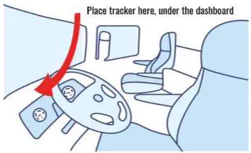
Place the FJ2500 in or on the vehicle:
Once proper device operation has been verified by the LED light pattern, you can secure the device inside the vehicle dashboard.
The device needs to be placed inside or on the vehicle with the bottom label facing away from the sky.
Ideal device location is to mount the unit horizontally, high under the dashboard, close to the front windshield or in any place that provides a clear view of the sky.![]() It is important to ensure that there are no metallic obstructions above the device to provide the best possible view of the sky. This will offer the most accurate location reporting and consistent tracking.
It is important to ensure that there are no metallic obstructions above the device to provide the best possible view of the sky. This will offer the most accurate location reporting and consistent tracking.
Harness Diagram
The wiring terminates at a 12-pin Deutsch DTM06-12sa connector. There are several accessory harness options available upon request to support any installation requirement.
| PIN | SIGNAL | DESCRIPTION | COLOR |
| 1 | CAN2+ | CAN/J1939 2 High | White/Red |
| 2 | CAN2- | CAN/J1939 2 Low | White/Black |
| 3 | Rx | RS232 Serial Rx | Yellow |
| 4 | IN1 | Switched 12V/24V (Ignition Detection) | Purple |
| 5 | Tx | RS232 Serial Tx | Brown |
| 6 | GND | Ground Signal | Black |
| 7 | +VDC | +12VDC to +24VDC Power In | Red |
| 8 | In3 | Fixed Bias High Input 3 | White |
| 9 | ADC1 | Analog ADC1 | Blue |
| 10 | Out1 | Digital Output for Relay Driver | Green |
| 11 | CAN1+ | CAN/J1939 1 High | Grey |
| 12 | CAN1- | CAN/J1939 1 Low | Orange |
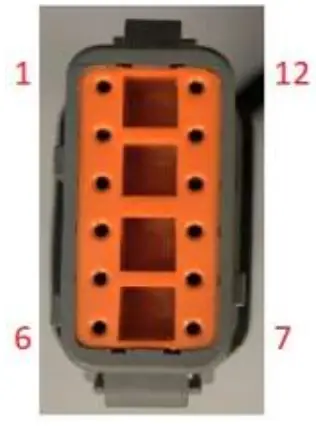 DTM06-12sa Harness native to FJ2500LA-12D and FJ2500MG-12D.
Troubleshooting Tips
- If the device LEDs do not operate as expected, or as described above, turn the vehicle on and allow several more minutes for the device to initiate.
- If a device is installed on a non-powered asset and the internal battery is low or depleted, it will not come out of sleep mode until an external power source is applied to the device.
- The device may not be able to obtain a GPS fix if the vehicle is indoors. This will lead to the GREEN LED never going solid.
- Cellular coverage is not guaranteed, if you are having problems with AMBER LEDs never turning solid, you can try to drive the vehicle to a different location to check if cellular coverage is a problem at the installation location.
- Ensure all connections to the J1939 connections on both the vehicle and the device wiring harness and 12-pin Deutsch connectors are fastened securely.
Specifications
Cellular Technology
| FJ2500LA-12D (LE910-NA1) | LTE Cat 1 – 4G | Bands 2, 4, 5, 12, 13 |
| Cat 1 – 3G | Bands 2, 5 | |
| FJ2500MG-12D (ME910G1-WW) | LTE Cat M – 4G | Bands 1, 2, 3, 4, 5, 8, 12, 13, 18, 19, 20, 25, 26, 27, 28, 66, 71, 85 |
| Cat M – 2G | Bands 2, 3, 5, 8 |
GPS Technology
| Location Technology | 56 channel GPS (with SBAS) |
| Tracking Sensitivity | -162 dBm |
| Location Accuracy | +/- 2.5m (CEP) |
| Cold Start Acquisition | 29 seconds |
| Hot Start Acquisition | 1 second |
Bluetooth/ WiFi/ NFC
| Bluetooth | V4.2/5.0 BLE with internal antenna (optional) |
Accelerometer
16G MEMS 3-axis accelerometer
Vehicle Interface
ISO-15765 Standard CAN, J1939 CAN Protocol, CANopen option
Physical Dimensions
| Dimensions | 83.0mm x 122.6mm x 39.0mm |
| Includes top and bottom mounting flanges | |
| Excluded cable and connector | |
| Weight | 272g |
Environment
| Storage Temp | -45c to 90c |
| Operating Temp | -40c to 85c while connected to main power |
| Relative Humidity | Up to 100% non-condensing |
| IP Rating | IP66K/IP67 |
| Vehicle Transient Surges | ISO 7637 – 12/24 VDC |
| Drop Test | 1.2 meter, 6 sides |
| ESD | 1 second pulses +- 4kV, +- 8kV indirect |
| Vehicle Vibration | SAE J1455 |
| Mechanical Shock | EN 60068-2-6, 27, 29 |
| Temperature and Humidity | EN 60068-2-14, 30 |
Power
| Internal Battery | 5200 mAh Rechargeable Li-Ion battery |
| Input Power Range | 6-90 VDC (12/24/48/72V vehicles) |
| Tracking Mode | <70mA average @12VDC |
| Idle Mode | <14mA average @12VDC |
| Sleep Mode | <2mA average @12VDC* |
| Deep Sleep Mode | <250µA average @12VDC* |
*Note: Sleep mode power draw may vary depending on device sleep settings.
FCC Statement
This device complies with part 15 of the FCC Rules. Operation is subject to the following two conditions:
- This device may not cause harmful interference, and
- This device must accept any interference received, including interference that may cause undesired operation.
This equipment has been tested and found to comply with the limits for a Class B digital device, pursuant to part 15 of the FCC Rules. These limits are designed to provide reasonable protection against harmful interference in a residential installation. This equipment generates, uses and can radiate radio frequency energy and, if not installed and used in accordance with the instructions, may cause harmful interference to radio communications. However, there is no guarantee that interference will not occur in a particular installation. If this equipment does cause harmful interference to radio or television reception, which can be determined by turning the equipment off and on, the user is encouraged to try to correct the interference by one or more of the following measures:
- Reorient or relocate the receiving antenna.
- Increase the separation between the equipment and receiver.
- Connect the equipment into an outlet on a circuit different from that to which the receiver is connected.
- Consult the dealer or an experienced radio/ TV technician for help.
Changes or modifications not expressly approved by the manufacturer could void the user’s authority to operate the equipment.
FCC RF Radiation Exposure Statement
This equipment complies with FCC radiation exposure limits set forth for an uncontrolled environment. To comply with FCC RF Exposure compliance requirements, this grant is applicable to only Mobile Configurations. The antennas used for the transmitter must be installed to provide a separation distance of at least 20cm from all persons and must not be co‐located or operating in conjunction with any other antenna or transmitter.
ISED Warning statements
This device complies with Canada’s licence-exempt RSSs. Operation is subject to the following two conditions:
- This device may not cause interference; and
- This device must accept any interference, including interference that may cause undesired operation of the device.
This equipment complies with IC RSS-102 radiation exposure limits set forth for an uncontrolled environment. This equipment should be installed and operated with a minimum distance of 20cm between the radiator and any part of your body.
This Class B digital apparatus complies with Canadian ICES-003.
![]() V.1.2 MAR 2023
V.1.2 MAR 2023


