FS M6200 Series Multi-Service WDM Optical Transport Platform
Product Information
M6200 Series WDM Network
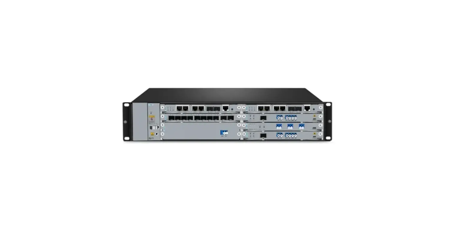
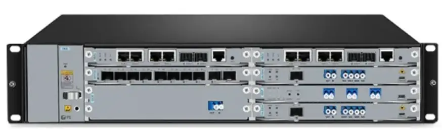
The FS M6200 Series Platform is a managed, flexible, and scalable architecture for fiber networks. It can support EDFA, OEO, OLP, DCM, and other M6200 Series Infrastructure Modules to construct a multi-service optical transmission network platform.
- The M6200 Series Infrastructure Modules are designed as 1-slot card type or 2-slot card type to match the managed chassis. The 1-slot module includes OEO, DWDM EDFA, OLP, DWDM Red/Blue Filter, DCM(40km), OSC, NMU, etc. The 2-slot module includes MUX, DEMUX, and DCM(80km).
- The M6200 Series Managed Chassis is available in two types: M6200-CH2U and M6200-CH5U. The M6200-CH2U has seven chassis slots, and the M6200-CH5U has 15 chassis slots.
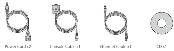
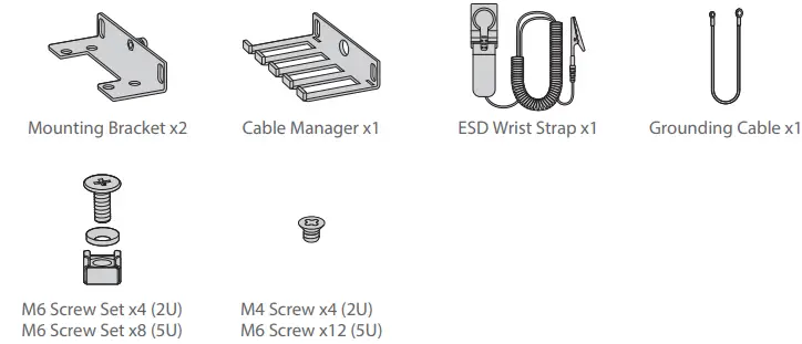
- The product comes with accessories including power cords, console cables, Ethernet cables, mounting brackets, cable managers, ESD wrist straps, grounding cables, and M6 screw sets.
Product Usage Instructions
- Before powering on the M6200 Series WDM Network, ensure that all cables are properly connected and the modules are installed correctly in the chassis.
- Connect the power cords to the M6200 Series Managed Chassis and plug them into a power outlet.
- Connect a console cable and an Ethernet cable to the M6200 Series Managed Chassis to configure the device.
- Use the NMU (Network Management Unit) to manage and monitor the M6200 Series WDM Network.
- The M6200 Series Infrastructure Modules can be used to construct a multi-service optical transmission network platform. Refer to the product manual for specific usage instructions on each module.
- If any alarm appears on the device, consult the product manual to troubleshoot the issue.
- If the fan unit needs to be replaced, follow the instructions in the product manual and finish the operation within two minutes to avoid overheating.
For more detailed information on the installation, configuration, and usage of the M6200 Series WDM Network, refer to the product user manual.
Introduction
- FS M6200 Series Platform provides a managed, flexible and scalable architecture for fiber networks. It can support EDFA, OEO, OLP, DCM and other M6200 Series
- Infrastructure Modules to construct a multi-service optical transmission network platform.

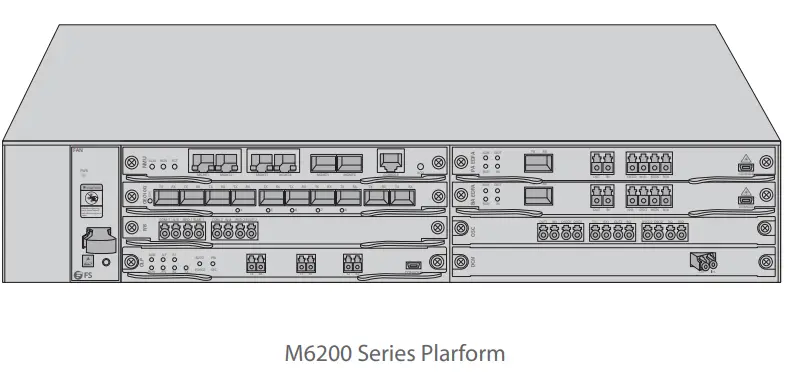
M6200 Series Platform Overview
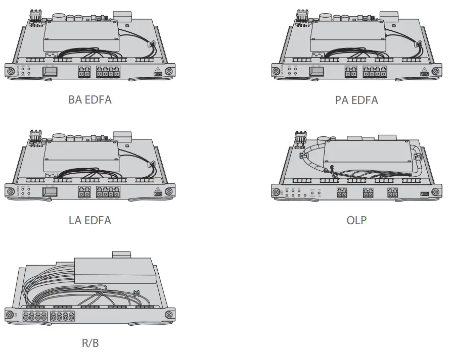
M6200 Series Infrastructure Modules
- Slot Card Type


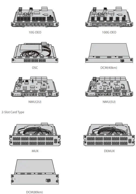
NOTE:
- M6200 series modules are designed as 1-slot card type or 2-slot card type to match the managed chassis.
- 1-slot module: OEO, DWDM EDFA, OLP, DWDM Red/Blue Filter, DCM(40km), OSC, NMU, etc.
- 2-slot module: MUX, DEMUX, DCM(80km).
M6200 Series Managed Chassis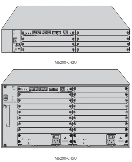
| Chassis Type | Chassis Slot |
| M6200-CH2U | 7pcs |
| M6200-CH5U | 15pcs |
Accessories

DWDM Mux Demux Module
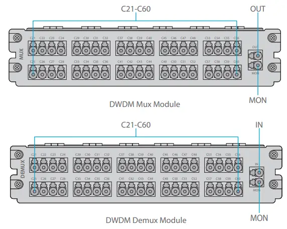
Front Panel Port
| Port | Port Type | Description |
| C21-C60 | LC/UPC | Mux/Demux Channel Port |
| OUT | Optical Singal Output Port | |
| IN | Optical Singal Input Port | |
| MON | Input/Output Optical Power Monitoring Port |
DWDM EDFA (Erbium Doped Fiber Amplifier)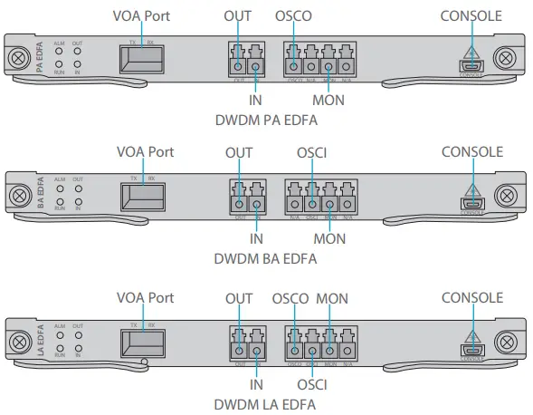
Front Panel Port
| Port | Port Type | Description |
| VOA Port | SFP | Optical Power Attenuation Adjusting Port for SFP VOA |
| OUT | LC/UPC | Optical Signal Output Port |
| IN | Optical Signal Input Port | |
| OSCO | Optical Supervisory Channel Output Port | |
| OSCI | Optical Supervisory Channel Input Port | |
| MON | Optical Signal Monitoring Port | |
| CONSOLE | Micro USB | Debugging & Upgrading Port |
Front Panel LED
| LED | Alarm State | Normal State | Description |
|
ALM | Always-ON: There is an alarm of the power supply, the fan, or the NMU module. | Light OFF | Module State Alarm |
| Quick Flash: The module type does not match. | |||
| RUN | Always OFF: The module is not normally enabled. | Slow Flash | Module Run |
| IN | Always Red: There is a LOS alarm at the port. | Always Green | Input Optical Power Alarm |
| OUT | Always OFF: The port is not enabled. |
10G OEO Transponder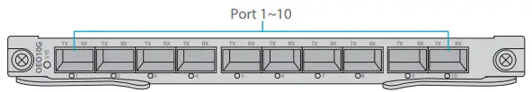
Front Panel Port
| Port | Port Type | Description |
| Port 1~10 | SFP/SFP+ | Optical Transceiver Signal Transmitting Port |
Front Panel LED
| LED | Status | Description |
| SYS | Slow Flash of Green Light | There is no alarm of the module. |
| Quick Flash of Red Light | The module type does not match. | |
| Slow Flash of Red Light | There is alarm of the module. | |
| Always Red | The module is enabling. | |
| 1~10 | Always Green | There is no LOS alarm of the port. |
| Always Red | There is LOS alarm of the port. | |
| Always OFF | The port is disabled. |
Signal Protocol
| Service | Type | Rate |
| STM-1 |
SDH Service | 155.52Mbit/s |
| STM-4 | 622.08Mbit/s | |
| STM-16 | 2.488Gbit/s | |
| STM-64 | 9.95Gbit/s | |
| ESCON | SAN Service | 200Mbit/s |
| FC100 | 1.06Gbit/s | |
| FC200 | 2.12Gbit/s | |
| DVB-ASI. SDL | Digital TV Service | 270Mbit/s |
| HD-SDI | HDTV Service | 1.485Gbit/s |
| GE |
Ethernet Service | 1.25Gbit/s |
| FE | 125Mbit/s | |
| CPRI Option1 | 0.6144Gbit/s | |
| CPRI Option2 | 1.2288Gbit/s | |
| CPRI Option3 | 2.4576Gbit/s | |
| 10GE LAN | 10.31Gbit/s | |
| 10GE WAN | 9.95Gbit/s | |
| OTU2 | OTN Service | 10.71Gbit/s |
| OTU2e | 11.1Gbit/s |
100G OEO Transponder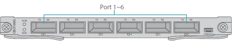
Front Panel Port
| Port | Port Type | Description |
| Port 1~6 | QSFP+/QSFP28 | 40/100Gbps Optical Transceiver Signal Transmitting Port |
Front Panel Port
| LED | Status | Description |
| ALM | Always Red | There is alarm of the Power, Fan and NMU module. |
| Quick Flash of Red Light | Ther module type does not match. | |
| Always OFF | There is no alarm of the module. | |
| RUN | Slow Flash of Green Light | The module is normal. |
| Always OFF | The module does not work. | |
|
1~6 | Always Green | There is no LOS alarm of the port. |
| Always Red | There is LOS alarm of the port. | |
| Quick Flash of Red Light | The transceiver does not match. | |
| Always OFF | The port is disabled. |
DCM (Dispersion Compensation Module)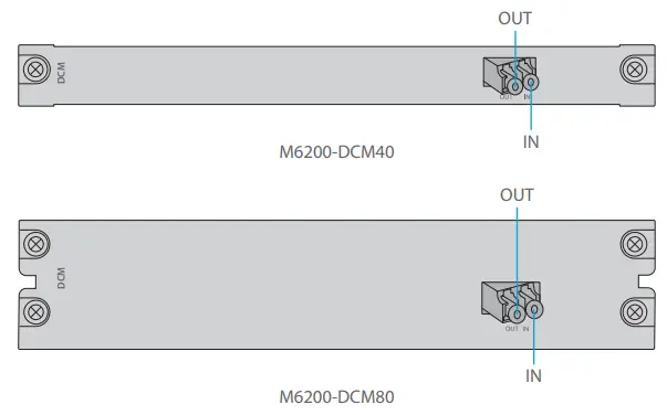
Front Panel Port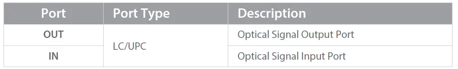
OSC Module (Optical Supervisory Channel Module)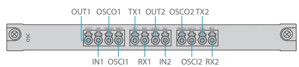
Front Panel Port
| Port | Port Type | Description |
| IN1/2 |
LC/UPC | Transmission Line Side Optical Singal Input Port |
| OUT1/2 | Transmission Line Side Optical Singal Output Port | |
| OSCI1/OSCI2 | Optical Supervisory Channel Input Port | |
| OSCO1/OSCO2 | Optical Supervisory Channel Output Port | |
| TX1/2 | WDM Demultiplexing Optical Singal Input Port | |
| RX1/2 | WDM Multiplexing Optical Singal Output Port |
1+1 OLP (Optical Line Protection)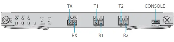
Front Panel Port
| Port | Port Type | Description |
| TX/RX | LC/UPC | Input/Output Port Connected to the Transmission Equipment |
| T1/R1 | Main Optical Signal Transmitting Port/Receiving Port | |
| T2/R2 | Backup Optical Signal Transmitting Port/Receiving Port | |
| CONSOLE | Micro USB | Debugging & Upgrading Port |
Panel Key Instruction
| Key | Function | Description |
| AUTO/FORCE | Press for switching auto mode or manual mode | Switching Working Mode |
| PRI/SEC | Press for switching work channel of primary/second state | Switching Working Channel |
Front Panel LED
| LED | Status | Description |
| ALM | Always ON | There is alarm of the sub-module. |
| Quick Flash | The module type does not match. | |
| Always OFF | The alarm does not exist. | |
| RUN | Slow Flash | The module works normally. |
| Always OFF | The module is not normally enabled. | |
| A/F | Always ON | The module is in automatic mode. |
| Always OFF | The module is in manual mode. | |
| P/S | Always ON | The line is in primary channel state. |
| Always OFF | The line is in secondary channel state. | |
| TX/R1/R2 | Always ON | The line power is normal. |
| Always OFF | The line power is lower than the threshold. |
Managed Chassis
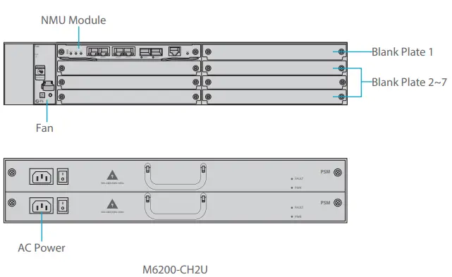
Front Panel Port
| Slots | Description |
| NMU Module | Network Management Unit(NMU), the main control module of chassis |
| Blank Plate 1 | Used for 1+1 NMU module backup or M6200 series business module |
| Blank Plate 2~7 | Used for 1-slot/2-slot M6200 series business module |
| Fan | Support field-replacedable and hot-swappable |
| AC Power | AC power supply, 90VAC~264VAC, 45Hz~65Hz, supports 1+1 backup |
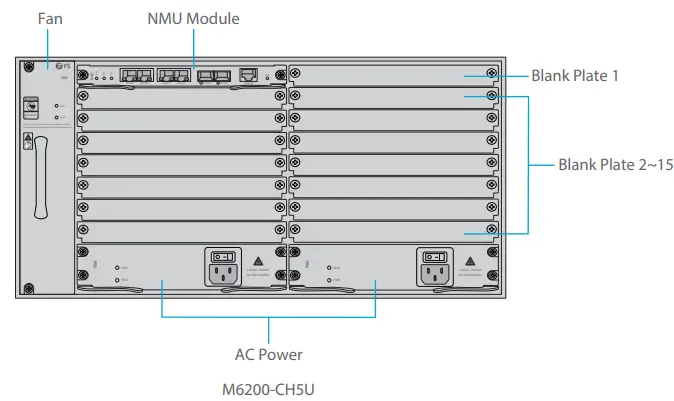
Front Panel Port
| Slots | Description |
| NMU Module | Network Management Unit(NMU), the main control module of chassis |
| Blank Plate 1 | Only used for 1+1 NMU module backup |
| Blank Plate 2~15 | Used for 1-slot/2-slot M6200 series business module |
| Fan | Support field-replacedable and hot-swappable |
| AC Power | AC power supply, 110VAC~260VAC, 45Hz~65Hz, supports 1+1 backup |
Networking Management Unit
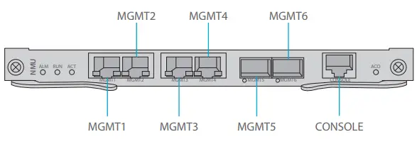
Front Panel Port
| Port | Port Type | Rate | Description |
| MGMT 1~4 | RJ45 ETH | 10/100M Auto-negotiate | 1 Connect to the local network management computer 2 Interface for NMS concatenation equipment |
| MGMT5~6 | SFP | 100M | Out of band OSC management |
| CONSOLE | RJ45 ETH | / | Debugging & Upgrading port |
Front Panel LED
| LED | Status | Description |
| ALM | Always ON | There is alarm on the power supply, the fan or the NMU Module. |
| Always OFF | There is no alarm. | |
| RUN | Quick Flash | The module works normally. |
| Always OFF | The module is not normally enabled. | |
| ACT | Always ON | The module is the primary module. |
| Always OFF | The module is the secondary module. |
Site Environment
- Keep the equipments indoors. If it is in rainy season or in humid environment, dehumidification measures must be taken.
- Ensure there is no water on the storage floor and no leakage to the packing box of the equipment.
- Avoid automatic fire fighting facilities, heating system and other places where leakage may occur.
Installing
Wearing ESD Wrist Strap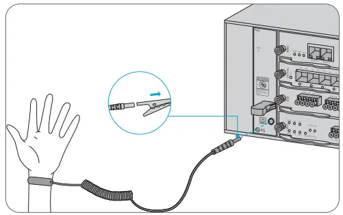
- Before touching any device or module, wear an ESD wrist strap or ESD gloves to protect sensitive components against electrostatic discharge from the human body.
- Connect other end of the ESD wrist strap to the PGND point on the chassis.
Installing Business Module
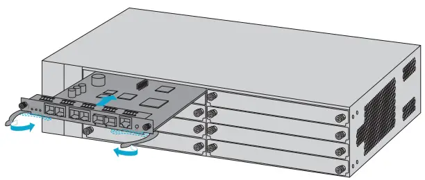
- Hold the ejector levers on the front panel of the module and raise them.
- Push the module gently along the guide rail until the module cannot go any further. Then lower the two ejector levers of the module.
Installing Mounting Brackets
- Secure the mounting brackets to the two sides of the M6200 series managed chassis with 8x M4 screws.
Rack Mounting
- Put the M6200 series managed chassis on the shelf in the cabinet.
- Install and tighten the panel with 4 sets of M6 screws.
- Cable manager can be installed together with mounting brackets to the cabinet.
Grounding the M6200 Series Managed Chassis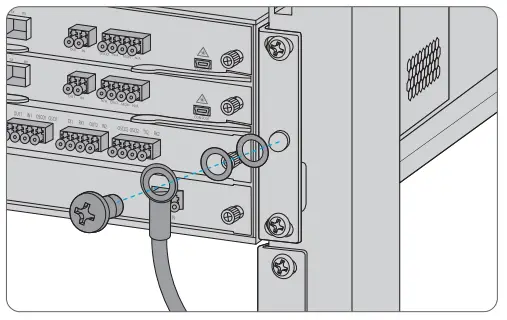
- Secure the grounding lug to the grounding point on the chassis front panel with the washers and screws.
- Connect the other end of the cable to a proper earth ground, such as the rack in which M6200 series is mounted.
CAUTION: The earth connection must not be removed unless all supply connections have been disconnectsd.
Connecting Power Cord
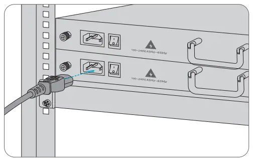
- Plug AC power cord into the power port on the front panel of AC power module.
- Connect the other end of the power cord to an AC power source.
WARNING: Do not install power cables while the power is on.
Connecting to the Management Ports
SFP Management Port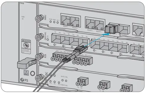
- Plug the compatible SFP transceiver into the SFP port on the front of NMU module.
- Connect a fiber optic cable to the transceiver. Then connect the other end of the cable to another fiber device, such as a switch.
RJ45 Management port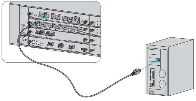
- Connect one end of the standard RJ45 Ethernet cable to the MGMT1&2 port on the front of NMU module.
- Connect the other end of cable to a computer.
NOTE:
- SFP management port is designed for long-haul management more than 100m.
- RJ45 management port is designed for short-haul management less than 100m.
- You can start your management by selecting one cf the above six management ports.
Configuring the M Series Platform
Configuring the M Series Platform Using the Web-based lnterface
- Step 1: Connect your computer with the network cable to any Ethernet MGMT port of the NMU module.
- Step 2: Get the NMS software from the CD of chassis accessories or download the file “NMS software” online, and then install it.

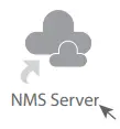
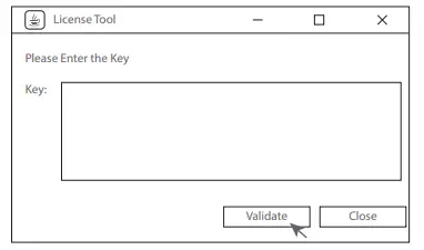
- Step 3: Double Click “NMS Server” icon on the desktop and the dialogue box of license validation will pop up. Enter the license key (included in the CD) to finish validation. (If you can’t find the license key, please contact FS sales manager for help.)

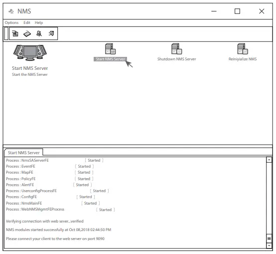
- Step 4: Then the NMS server interface pops up. Double click “Start NMS Server” to run the server, when it prompts “Please connect your client to the web server on port: 9090”, it means that you have successfully started the NMS server. And then you can close the NMS Server window, the server is still running in the background.

- Step 5: Open a browser window. (Recommend IE11.0 and above version or Google Chrome browser).
- If you log in from local NMS host, enter localhost:9090 in the address bar to open the login interface.
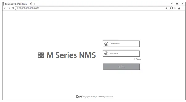
- If you log in from other remote host, enter the server IP address XXX.XXX.XXX.XXX:9090 (IP address of NMS server) to open the login interface.
- Step 6: Enter correct user name and password (For the administrator, the default login user name is “root”, and the default password is “public”), as shown in the figure below:

- Step 7: Click login, you are now ready to configure M series platform
NOTE: Refer to the M SERIES NETWORK MANAGEMENT USER MANUAL online for further information
Troubleshooting
Module LEDs Working Abnormally
- Check the power cable connections at the M6200 series managed chassis and the power source.
- Make sure that all cables are used correctly and comply with the power specifications.
- Make sure that business modules are in the right position in the M6200 series managed chassis.
Accessing the Web-based Configuration Page Unsuccessfully
- Check MGMT ports LED on the NMU module and make sure the Ethernet cable is connected properly.
- Try another port on the NMU module and make sure the Ethernet cable is suitable and works normally..
- Pow M6200 series managed chassis. After a while, power it on again.
- Make sure the IP address of your NMS server is correctly configured.
- usiness Module Cannot Be Added
Enter through CMD.
- Ping business module IP to check whether it can communicate.
- Check whether normal communication can be made between business module and NMU module.
- Change another business module.
Online Resources
- Download https://www.fs.com/download.html
- Help Center https://www.fs.com/service/help_center.html
- Contact Us https://www.fs.com/contact_us.html
Product Warranty
- FS ensures our customers that any damage or faulty items due to our workmanship, we will o er a free return within 30 Days from the day you receive your goods. This excludes any custom made items or tailored solutions.
- Warranty: M6200 series enjoy 2 years limited warranty against defect in materials or workmanship. For more details about warranty, please check at : https://www.fs.com/policies/warranty.html
- Return: If you want to return item(s), information on how to return can be found at: https://www.fs.com/policies/day_return_policy.html
FCC
Compliance Information
Note: This equipment has been tested and found to comply with the limits for a Class B digital device, pursuant to part 15 of the FCC Rules. These limits are designed to provide reasonable protection against harmful interference in a residential installation. This equipment generates, uses and can radiate radio frequency energy and, if not installed and used in accordance with the instructions, may cause harmful interference to radio communications. However, there is no guarantee that interference will not occur in a particular installation. If this equipment does cause harmful interference to radio or television reception, which can be determined by turning the equipment off and on, the user is encouraged to try to correct the interference by one or more of the following measures:
- Reorient or relocate the receiving antenna.
- Increase the separation between the equipment and receiver.
- Connect the equipment into an outlet on a circuit different from that to which the receiver is
connected. - Consult the dealer or an experienced radio/TV technician for help.
- This device complies with part 15 of the FCC Rules. Operation is subject to the following two conditions:
- this device may not cause harmful interference, and
- this device must accept any interference received, including interference that may cause undesired operation.
CAUTION:
- Any changes or modifications not expressly approved by the grantee of this device could void the user’s authority to operate the equipment.
- Responsible party (only for FCC matters)
- FS.COM Inc.
- 380 Centerpoint Blvd, New Castle, DE 19720, United States https://www.fs.com
- FS.COM GmbH hereby declares that this device complies with Directive 2014/30/EU. A copy of the EU Declaration of Conformity is available at
- www.fs.com/company/quality_control.html
- FS.COM LIMITED
- 24F, Infore Center, No.19, Haitian 2nd Rd, Binhai Community, Yuehai Street, Nanshan District, Shenzhen City
- FS.COM GmbH
- NOVA Gewerbepark Building 7, Am
- Gfild 7, 85375 Neufahrn bei Munich, Germany
- Copyright © 2021 FS.COM All Rights Reserved.
References
 FS.com - Data Center, Enterprise, Telecom
-
Quality Certification - FS.com
-
Ein weltweit führender Anbieter von Hochgeschwindigkeits-Konnektivitätsgeräten und -lösungen. - FS.com Deutschland
-
FS.com - Data Center, Enterprise, Telecom
-
Contact Us - FS.com
-
Kontakt - FS.com Deutschland
-
Technische Dokumente - FS.com Deutschland
-
Rückgaberecht - FS.com Deutschland
-
Ein weltweit führender Anbieter von Hochgeschwindigkeits-Konnektivitätsgeräten und -lösungen. - FS.com Deutschland
-
Hilfezentrum - FS.com Deutschland
-
Technical Documents - FS.com
-
Fournisseur leader de solutions et matériels de connectivité à haut débit - FS.com France
-
Comment Nous Contacter - FS.com France
-
Documents techniques - FS.com France
-
Politique de retour - FS.com France
-
Fournisseur leader de solutions et matériels de connectivité à haut débit - FS.com France
-
Centre d'aide - FS.com France
-
Return Policy - FS.com
-
Products Warranty - FS.com
-
Help Center - FS.com


