
SaltDogg TGS03 Cubic Foot Tailgate Spreader Installation Guide
Safety Precautions
![]() WARNING
WARNING
Observe the following Safety Precautions before, during and after operating this spreader. By following these precautions and common sense, possible injury to persons and potential damage to this machine may be avoided.
- Read this entire Installation Instruction before operating this spreader.
- Read all safety decals on the spreader before operating.
- Verify that all personnel are clear of the spreader spray area before starting or operating this spreader.
- Do not adjust, clean, lubricate or unclog material jams without first turning off the spreader.
- Make sure the spreader is securely fastened to the vehicle in accordance with this manual.
- Do not operate a spreader that is in need of maintenance or repairs.
- Always disconnect the battery before removing or replacing electrical components.
Spreader Assembly
Check contents of box against parts list to make sure all components are included. When ordering replacement or spare parts refer to parts list for part numbers.
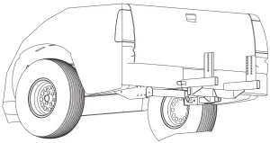
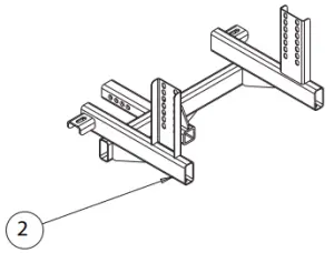
- Slide frame #3019400 into hitch receiver. Fig. 1.

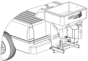
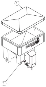
- Slide hopper assembly #3019372 between frame uprights with front portion rested on the truck’s bumper. Fig. 2.

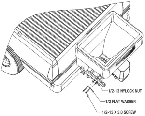
- Align holes in rear portion of the hopper with slots in frame uprights. Use slots which will position spreader with a slight upward tilt. Secure hopper assembly to frame using ½-13 x 3.0 screws, flat washers and nuts. Fig.3. Do not tighten fasteners at this time. Apply Antiseize on all stainless steel fasteners to avoid galling!

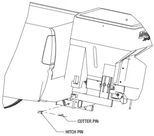
WARNING SPREADER CANNOT BE SUPPORTED BY FRAME ONLY! SPREADER HOPPER MUST REST ON BUMPER OR SIMILAR STRUCTURE ATTACHED TO TRUCK FRAME - Slide hopper and frame towards tailgate leaving about 3/8” to ½” space. Align closest holes in hitch receiver with holes in frame. Secure frame in hitch receiver using 5/8 hitch pin and cotter pin. Fig.4.

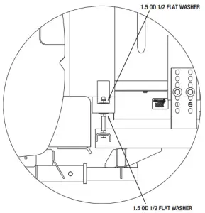
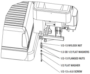
- Assembly ½-13 x 6.0 screws as shown in Fig.5. Make sure that nuts located between hopper flange and frame positioned exactly as shown. These nuts must not be in contact with hopper and frame at this time.

- Tighten nuts located in hopper pockets evenly on both sides of the spreader (10-15 ft-lb’s. torque). Then tighten bolts in frame uprights. Finally tighten nuts located between hopper and frame. They must look as shown in Fig.6. After this procedure spreader should be securely attached to trucks bumper and frame.
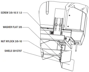
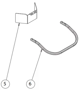
- Attach shield #3015707 to trough bracket as shown in Fig.7

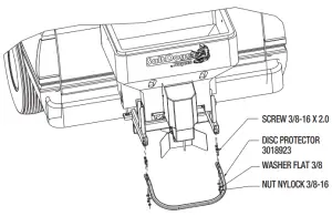
- Attach spinner protector #3018923 to spreader frame as shown in Fig.8.

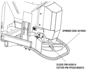
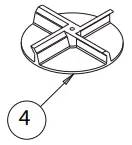
- Attach spinner disk to gear motor shaft as shown in Fig.9.Secure disk on shaft using clevis pin and cotter pin.

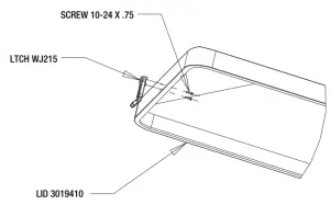
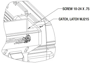
- Attach bracket and handle of draw latch to lid #3019410 using 2 10-24 screws as shown in Fig.10. Attach draw latch catcher to the hopper as shown in Fig.11.


THIS IS WIRE GROUND ELECTRICAL SYSTEM! NO CONNECTIONS TO TRUCK’S FRAME OR BODY ALLOWED!
NOTE: Always disconnect battery before attempting to install electrical components on your vehicle. Mount the controller in a convenient location in the truck cab. It is recommended not to mount the controller directly in front of heat vents. Allow ample air space around controller.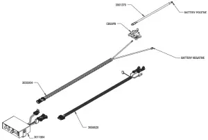
Installing Controller and Wiring
- Route both wire harnesses into truck cab through firewall (it maybe necessary to drill holes). Insulate hole to avoid water leaks.
- Insure no wires are nicked or damaged during installation.
- Connect the 4-pin connecter on the wire harness to the control box.
- Connect the 2-pin connector on the power cable to the control box.
- Lay out a path for the power cable to the battery, use quick ties to secure power cable.
DO NOT CONNECT TO BATTERY AT THIS TIME!
- Lay out path for wire harness to the rear of the vehicle. It is recommended to stay clear of the exhaust system. Excess heat can damage the wire harnesses. Use quick ties to secure harness to underbody.
- Connect the wire harness to the motor and vibrator.
- Connect the power and ground cables directly to the battery.
- Insure all functions of the controller are working properly.
- Note: direction of spinner may be changed by interchanging the motor leads.
Spreader Operation
- Due to the rate at which materials absorb moisture differently, some materials may not perform as desired. Therefore, the substitution of an alternative material may be necessary for optimum performance.
- When filling hopper use only screened material. Prevent large chunks of material and debris from getting into hopper and cause operational problem or damage.
- Material must never be left in the hopper for extended period of time. Material will absorb moisture, bind, harden and may prevent spreader from proper operation or may damage the spreader.
- To start spreader make sure that truck engine is running. Flip POWER switch in ON position. Switch will illuminate. Spreader motor will accelerate to full speed and then it will slow down to previously dialed speed.
- To adjust material flow rate and spreading distance, simply rotate speed knob to desired speed. Spreader can be put in full speed mode for short time by pressing and holding BLAST button.
- To activate and deactivate vibrator (optional) press VIBRATOR button, if equipped.
- Material flow and pattern can be adjusted by opening/ close adjustable discharge on the trough bottom. Be careful adjusting discharge opening. Closing this opening too much will created back pressure and stall gear motor.
Optional vibrator installation
To install optional vibrator, order kit #3020340. Drill 3/8 clearance holes thru hopper using bind holes as guides. Place plate inside hopper; align holes in plate with holes in hopper. Place vibrator on outer hopper wall and secure it to hopper using 4 carriage bolts 3/8-16 x 3.25 and 4 nylock nuts 3/8-16. Connect vibrator cable to mating connector on wire harness 3008620.
Check fasteners every 5-7 hours of operation. Retighten if necessary.
Controller Warnings
Check controller instruction sheet for latest controller updates, troubleshooting codes. Controller instruction sheet is inside controller shipping box.
IMPORTANT! INSTALLER, DO NOT DISCARD CONTROLLER INSTRUCTION SHEET. STAPLE SHEET TO SPREADER MANUAL AND GIVE TO END USER!
Maintenance Instructions
- Wash spreader after every use. Make sure no material left under auger and/or inside trough.
- Inspect and retighten fasteners after every 5-7 hours of operation.
- Lubricate bearing every 7-10 hours of operation using general automotive grease.
- Inspect terminals/ connectors every time you disconnect spreader from wire harness. Apply thin layer of dielectric grease on terminals. If any tarnish/corrosion found, clean terminals and apply dielectric grease.
End of Season Maintenance
- Wash spreader. Make sure no material or residue left in and outside hopper.
- Lubricate bearing using general automotive grease.
- Inspect wire harness, connectors for broken insulation, missing components. Replace if necessary.
- Apply dielectric grease on all electrical connectors.
- Store hopper indoors, in dry, cool place.
- Inspect, clean and repaint frame.
- Remove controller from truck. Store controller indoors, in dry, cool place.
TGS03 Tailgate Auger
Bill of Materials
| ITEM | PART NO. | QTY | DESCRIPTION |
| 1 | 3019372 | 1 | HOPPER ASSEMBLY |
| 3026555 | 1 | HOPPER ASSEMBLY, RED | |
| 3026557 | 1 | HOPPER ASSEMBLY, YELLOW | |
| 2 | 3019400 | 1 | FRAME TGS03 |
| 3 | 3019410 | 1 | LID TGS03 |
| 3026564 | 1 | LID TGS03, RED | |
| 3026565 | 1 | LID TGS03, YELLOW | |
| 4 | 3019561 | 1 | SPINNER, 12 IN TGS |
| 5 | 3015707 | 1 | SHIELD TGS07 |
| 6 | 3018923 | 1 | DISC PROTECTOR |
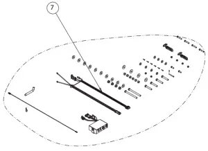
| 7 | 3019408 | 1 | HARDWARE BAG TGS03 |
TGS03 Hopper Assembly
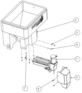
Bill of Materials
| ITEM | PART NO. | QTY | DESCRIPTION |
| 1 | 3015383 | 1 | TROUGH ASSEMBLY TGS07 |
| 2 | 3019471 | 1 | HOPPER POLY |
| 3026554 | 1 | HOPPER POLY, RED | |
| 3026556 | 1 | HOPPER POLY, YELLOW | |
| 3 | FWF031075006SS | 6 | WASHER, 5/16 SAE SST |
| 4 | 3006721 | 6 | SCREW, HEX HD, 5/16-18 X 3/4 GR5 SS |
| 5 | 3015694 | 1 | MOTOR COVER TGS07 |
| 6 | 3015925 | 4 | SCREW #14X1.25 SST |
| 7 | 3017984 | 1 | CAP ROUND 1.312 ID VINYL BLACK |
TGS03 Trough Assembly
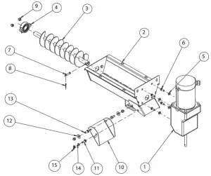
Bill of Materials
| ITEM | PART NO. | QTY | DESCRIPTION |
| 1 | 3015377 | 1 | GEAR MOTOR DUAL SHAFT .5 HP 12 VDC |
| 2 | 3015381 | 1 | TROUGH WELDMENT, TGS07 |
| 3 | 3015382 | 1 | AUGER TGS07 |
| 4 | 1411000 | 1 | BEARING, 2-HOLE FLANGED 1″ |
| 5 | FWF031075006SS | 4 | WASHER, 5/16 SAE SST |
| 6 | 3006721 | 4 | SCREW, HEX HD, 5/16-18 X 3/4 GR5 SS |
| 7 | FPY031000150 | 1 | PIN, CLEVIS, 5/16 X 1-1/2, W/ 5/32 PH, ZN |
| 8 | 3014994 | 1 | PIN,COTTER,1/8IN X 1IN SST |
| 9 | FNE038016044SS | 4 | NUT, NYLOCK 3/8-16 X 7/16 SST |
| 10 | 3019374 | 1 | DISCHARGE, ADJUSTABLE |
| 11 | 3012144 | 1 | BOLT, RHSQN,.25-20X.5 SST |
| 12 | FWF038100007SS | 2 | WASHER, FLAT 3/8 USS SST |
| 13 | FCS038016075SS | 2 | SCREW, HHC-3/8-16 X 3/4 SST |
| 14 | FWF025063007SS | 1 | WASHER, FLAT 1/4 SAE SS |
| 15 | 3016751 | 1 | NUT,WING 1/4-20 SST |
TGS03 Hardware Bag
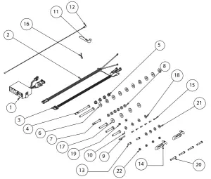
Bill of Materials
| ITEM | PART NO. | QTY. | DESCRIPTION |
| 1 | 3011864 | 1 | CONTROLLER TGS W/ VIBRATOR SWITCH |
| 2 | 3035934 | 1 | WIRE HARNESS, POWER TGS |
| 3 | 3008620 | 1 | WIRE HARNESS MAIN W/ VIBRATOR, TGS |
| 4 | 3017039 | 2 | SCREW, HEX HEAD CAP 1/2-13 X 6.00 SST FULL THREAD |
| 5 | 3001523 | 4 | NUT, HX FLNG-1/2-13 SST |
| 6 | 3000269 | 10 | WASHER, FLAT 1/2 USS, SST |
| 7 | 3001250 | 4 | SCREW, HHC-1/2-13 X 3 SST |
| 8 | FNE050013053SS | 6 | NUT, NYLOCK 1/2-13 SS |
| 9 | 1420014 | 1 | PIN CLEVIS, 1/4 X 2.5 |
| 10 | FPC007800075 | 1 | COTTER PIN, 5/64 X 3/4 |
| 11 | HP6253WC1 | 1 | PIN, 5/8 HITCH |
| 12 | 3001379 | 1 | BATTERY CABLE |
| 13 | FCS038016100SS | 2 | SCREW, HHC 3/8-16 X 1 304 SST |
| 14 | WJ215 | 2 | LATCH DRAW RUBBER |
| 15 | FBSH01002475SS | 6 | SCREW, BHC #10-24 X .75 SST |
| 16 | 1420016 | 1 | PIN, HAIR COTTER, CLEAR ZINC |
| 17 | 3017858 | 4 | WASHER FLAT .5 ID 1.5 OD SST |
| 18 | FWF038100007SS | 4 | WASHER, FLAT 3/8 USS SST |
| 19 | FNE038016044SS | 2 | NUT, NYLOCK 3/8-16 X 7/16 SST |
| 20 | FCS038016200 | 4 | SCREW, HHC 3/8-16 X 2 GR 5 ZP |
| 21 | FWF038100007 | 4 | WASHER, FLAT 3/8 USS ZINC |
| 22 | FNE038016044 | 4 | NUT, NYLOCK 3/8-16 X 7/16 ZINC |
| 3018421 | 1 | ANTI SEIZE LUBRICANT POUCH 5 GRAM | |
| CB50PB | 1 | CIRCUIT BREAKER |
SPREADER WARRANTY
This warranty replaces all previous warranties and no employee of this company is authorized to extend additional warranties, or agreements, or implications not explicitly covered herein. Buyers Products Company warrants all parts of the product to be free from defects in material and workmanship for a period of one (1) year. Parts must be properly installed and used under normal conditions. Normal wear is excluded.
Any part, which has been altered, including modifications, misuse, accident, or lack of maintenance will not be considered under this warranty.
The sole responsibility of Buyers Products Company under this warranty is limited to repairing or replacing any part(s), which are returned, prepaid, 30 days after such defect is discovered, and returned part(s) are found to be defective by Buyers Products Company.
Authorization from Buyers Products Company must be obtained before returning any part. The following information must accompany defective parts returned to Buyers Products Company: RMA #, spreader model, serial number, date installed, and distributor from whom purchased. Buyers Products Company shall not be liable for damage arising out of failure of any unit to operate properly, or failure, or delay in work, or for any consequential damages. No charges for transportation or labor performed on any part will be allowed under this warranty.


