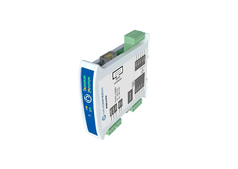
iSMACONTROLLI SFAR-S-ETH Modbus TCP-IP to Modbus RTU-ASCII Gateway Instructions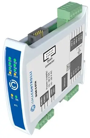
SPECIFICATION
| Power supply | Voltage | 10-38 V DC; 10-28 V AC |
| Power consumption | 7 W @ 24 V DC 9 VA @ 24 V AC | |
| Digital inputs | 4x, logical ‘0’: 0-3 V, logical ‘1’: 6-36 V | |
| Isolation 3650 Vrms | ||
| Relay outputs | 3x Relay outputs | |
| Resistive load AC1: 3 A @ 230 V AC or 3 A @ 30 V DC | ||
| Inductive load AC3. 75 VA @ 230V AC or 30 W @ 30 V DC | ||
| Contact material AgSnO2 | ||
| Interface | RS485, up to 128 devices on the bus | |
| Ethernet 10/100 Mbps | ||
| Baudrate | from 2400 to 115200 bps | |
| Ingress protection | IP40 – for indoor installation | |
| Temperature | Operating -10°C – +50°C; Storage – 40°C – +85°C | |
| Relative humidity | 5 to 95% RH (without condensation) | |
| Connectors | Max 2.5 mm2 | |
| Dimension | 119,1 mm x 101 mm x 22,6 mm | |
| Mounting | DIN rail mounting (DIN EN 50022) | |
| Housing material | Plastic, self-extinguishing PC/ABS | |
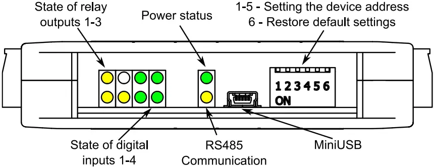
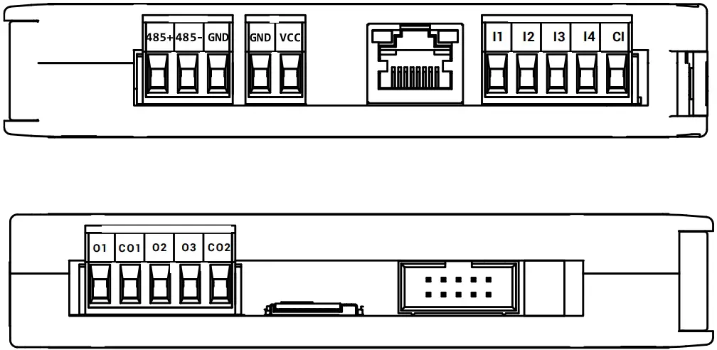
TOP PANEL
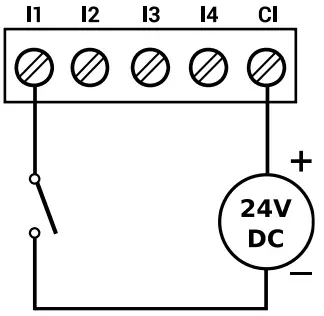
DIGITAL INPUTS
- Connection of input

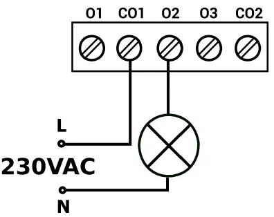
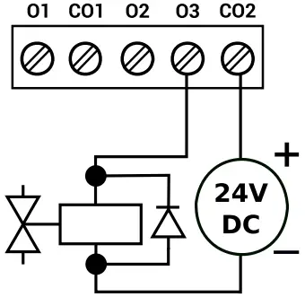
RELAY OUTPUTS
- Connection of resistive load

- Connection of electrovalve

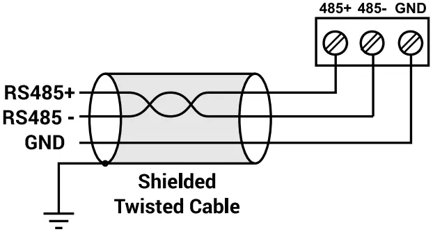
COMMUNICATION
- RS485 communication

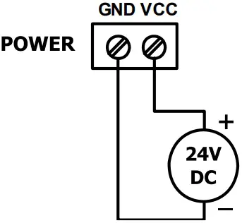
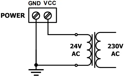
POWER SUPPLY
- DC Voltage

- AC Voltage

WARNING
- Note, an incorrect wiring of this product can damage it and lead to other hazards. Make sure the product has been correctly wired before turning the power ON.
- Before wiring, or removing/mounting the product, be sure to turn the power OFF. Failure to do so might cause electric shock.
- Do not touch electrically charged parts such as the power terminals. Doing so might cause electric shock.
- Do not disassemble the product. Doing so might cause electric shock or faulty operation.
- Use the product within the operating ranges recommended in the specification (temperature, humidity, voltage, shock, mounting direction, atmosphere etc.). Failure to do so might cause fire or faulty operation.
- Firmly tighten the wires to the terminal. Insufficient tightening of the wires to the terminal might cause fire
TERMINALS OF THE DEVICE
Registered access
| Modbus | Dec | Hex | Register Name | Access | Description |
| 30001 | 0 | 0x00 | Version/Type | Read | Version and Type of the device |
| 30002 | 1 | 0x01 | Address | Read | Module address SFAR-S-ETH |
| 40003 | 2 | 0x02 | Baud rate | Read & write | Transmission speed |
| 40004 | 3 | 0x03 | Stop bits | Read & write | Stop bits |
| 40005 | 4 | 0x04 | Parity | Read & write | Parity |
| 40007 | 6 | 0x06 | Modbus Mode | Read & write | Modbus protocol type |
| 40009 | 8 | 0x08 | Watchdog | Read & write | Function watchdog for outputs [ms] |
| 40013 | 12 | 0x0C | Default Outputs State | Read & write | Default state of outputslit bit → output active |
| 40014 | 13 | 0x0D | Operating mode | Read & write | Modbus mode TCP0 – Device Table; 1 – Gateway Modbus TCP |
| 40015 | 14 | 0x0E | Slow Rate | Read & write | Frequency of queries in Device Table mode [ms] |
| 40016 | 15 | 0x0F | Normal Rate | Read & write | Frequency of queries in Device Table mode [ms] |
| 40017 | 16 | 0x10 | Fast Rate | Read & write | Frequency of queries in Device Table mode [ms] |
| 40033 | 32 | 0x20 | Received packets LSR (Least Significant Reg.) | Read & write | The amount of received packets |
| 40034 | 33 | 0x21 | Received packets MSR (Most Significant Reg.) | Read & write | |
| 40035 | 34 | 0x22 | Incorrect packets LSR | Read & write | The amount of received incorrect packets |
| 40036 | 35 | 0x23 | Incorrect packets MSR | Read & write | |
| 40037 | 36 | 0x24 | Sent packets LSR | Read & write | The amount of sent packets |
| 40038 | 37 | 0x25 | Sent packets MSR | Read & write | |
| 30051 | 50 | 0x32 | Inputs | Read | Inputs status lit bit → input active |
| 40052 | 51 | 0x33 | Outputs | Read & write | Outputs status |
| 40053 | 52 | 0x34 | Counter 0 LSR | Read & write | 32-bits counter 0 |
| 40054 | 53 | 0x35 | Counter 0 MSR | Read & write | |
| 40055 | 54 | 0x36 | Counter 1 LSR | Read & write | 32-bits counter 1 |
| 40056 | 55 | 0x37 | Counter 1 MSR | Read & write | |
| 40057 | 56 | 0x38 | Counter 2 LSR | Read & write | 32-bits counter 2 |
| 40058 | 57 | 0x39 | Counter 2 MSR | Read & write | |
| 40059 | 58 | 0x3A | Counter 3 LSR | Read & write | 32-bits counter 3 |
| 40060 | 59 | 0x3B | Counter 3 MSR | Read & write | |
| 40061 | 60 | 0x3C | Reset counters | Read & write | Reset counter slit bit → counter reset |
INSTALLATION GUIDELINE

Please read the instruction before use or operating the device. In case of any questions after reading this document, please contact the iSMA CONTROLLI Support Team ([email protected]).
- Before wiring or removing/mounting the product, make sure to turn the power off. Failure to do so might cause an electric shock.
- Improper wiring of the product can damage it and lead to other hazards. Make sure that the product has been correctly wired before turning the power on.
- Do not touch electrically charged parts such as power terminals. Doing so might cause an electric shock.
- Do not disassemble the product. Doing so might cause an electric shock or faulty operation.
- Use the product only within the operating ranges recommended in the specification (temperature, humidity, voltage, shock, mounting direction, atmosphere, etc.). Failure to do so might cause a fire or faulty operation.
- Firmly tighten the wires to the terminal. Failure to do so might cause a fire.
- Avoid installing the product in close proximity to high-power electrical devices and cables, inductive loads, and switching devices. Proximity of such objects may cause an uncontrolled interference, resulting in an instable operation of the product.
- Proper arrangement of the power and signal cabling affects the operation of the entire control system. Avoid laying the power and signal wiring in parallel cable trays. It can cause interferences in monitored and control signals.
- It is recommended to power controllers/modules with AC/DC power suppliers. They provide better and more stable insulation for devices compared to AC/AC transformer systems, which transmit disturbances and transient phenomena like surges and bursts to devices. They also isolate products from inductive phenomena from other transformers and loads.
- Power supply systems for the product should be protected by external devices limiting overvoltage and effects of lightning discharges.
- Avoid powering the product and its controlled/monitored devices, especially high power and inductive loads, from a single power source. Powering devices from a single power source causes a risk of introducing disturbances from the loads to the control devices.
- If an AC/AC transformer is used to supply control devices, it is strongly recommended to use a maximum 100 VA Class 2 transformer to avoid unwanted inductive effects, which are dangerous for devices.
- Long monitoring and control lines may cause loops in connection with the shared power supply, causing disturbances in the operation of devices, including external communication. It is recommended to use galvanic separators.
- To protect signal and communication lines against external electromagnetic interferences, use properly grounded shielded cables and ferrite beads.
- Switching the digital output relays of large (exceeding specification) inductive loads can cause interference pulses to the electronics installed inside the product. Therefore, it is recommended to use external relays/contactors, etc. to switch such loads. The use of controllers with triac outputs also limits similar overvoltage phenomena.
- Many cases of disturbances and overvoltage in control systems are generated by switched, inductive loads supplied by alternating mains voltage (AC 120/230 V). If they do not have appropriate built-in noise reduction circuits, it is recommended to use external circuits such as snubbers, varistors, or protection diodes to limit these effects.

Electrical installation of this product must be done in accordance with national wiring codes and conform to local regulations.
Customer Service
 iSMA CONTROLLI S.p.A.
Via Carlo Levi 52, 16010 Sant’Olcese (GE) – Italy
[email protected]
www.ismacontrolli.com


