unicorecomm UM960L All Constellation Multi Frequency High Precision RTK Positioning Module User Manual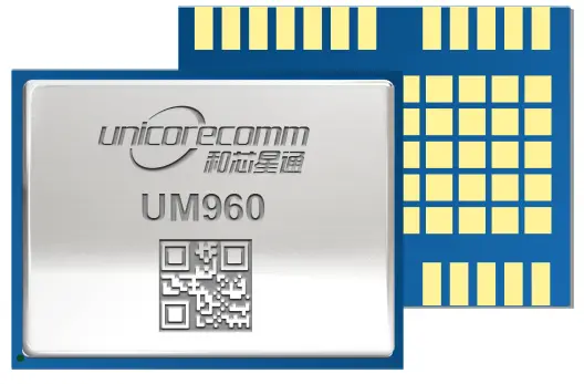
Revision History
| Version | Revision History | Date |
| R1.0 | First release | Aug., 2022 |
Legal Right Notice
This manual provides information and details on the products of Unicore Communication, Inc. (“Unicore”) referred to herein.
All rights, title and interest to this document and the information such as data, designs, layouts contained in this manual are fully reserved, including but not limited to the copyrights, patents, trademarks and other proprietary rights as relevant governing laws may grant, and such rights may evolve and be approved, registered or granted from the whole information aforesaid or any part(s) of it or any combination of those parts.
Unicore holds the trademarks of UNICORECOMM” and other trade name, trademark, icon, logo, brand name and/or service mark of Unicore products or their product serial referred to in this manual (collectively “Unicore Trademarks”).
This manual or any part of it, shall not be deemed as, either expressly, implied, by estoppel or any other form, the granting or transferring of Unicore rights and/or interests (including but not limited to the aforementioned trademark rights), in whole or in part.
Disclaimer
The information contained in this manual is provided “as is” and is believed to be true and correct at the time of its publication or revision. This manual does not represent, and in any case, shall not be construed as a commitments or warranty on the part of Unicore with respect to the fitness for a particular purpose/use, the accuracy, reliability and correctness of the information contained herein.
Information, such as product specifications, descriptions, features and user guide in this manual, are subject to change by Unicore at any time without prior notice, which may not be completely consistent with such information of the specific product you purchase.
Should you purchase our product and encounter any inconsistency, please contact us or our local authorized distributor for the most up-to-date version of this manual along with any addenda or corrigenda.
Foreword
This document describes the information of the hardware, package, specification and the use of Unicore UM960L modules.
Target Readers
This document applies to technicians who possess the expertise on GNSS receivers.
Introduction
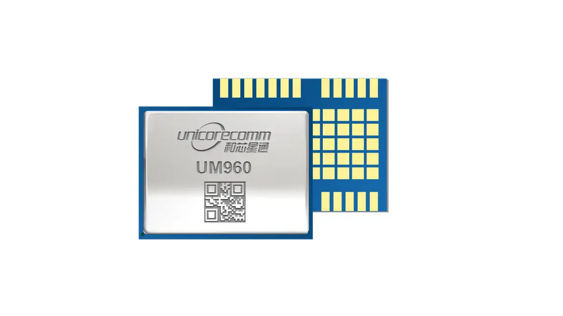
UM960L is a new generation of GNSS high precision positioning RTK module from
Unicore. It supports all constellations and multiple frequencies, and can simultaneously track GPS L1/L2/L5 + BDS B1I/B2I/B3I + GLONASS L1/L2+Galileo E1/E5a/E5b + QZSS L1/L2/L5. The module is mainly used in geological hazard monitoring, deformation monitoring, and high precision GIS.
UM960L is based on NebulasⅣTM, a GNSS SoC which integrates RF-baseband and high precision algorithms. Besides, the SoC integrates a 2 GHz dual CPU, a high speed floating point processor and a RTK co-processor with 22 nm low power design, and it supports 1408 super channels. All these above enable stronger signal processing.
UM960L features a compact size of 16.0 mm × 12.2 mm. It adopts SMT pads, supports standard pick-and-place, and supports fully automated integration of reflow soldering.
Furthermore, UM960L supports interfaces such as UART, I2C, which meets the customers’ needs in different applications.
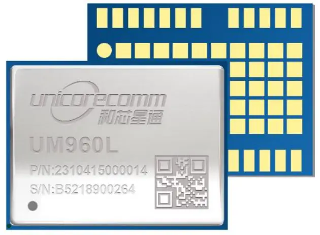
Figure 1-1 UM960L Module
Reserved interface, not supported currently.
Key Features
- High precision, compact size and low power consumption
- Based on the new generation GNSS SoC -NebulasIVTM, with RF-baseband and high precision algorithms integrated
- 16.0 mm × 12.2 mm × 2.4 mm, surface-mount device
- Supports all-constellation multi-frequency on-chip RTK positioning solution
- Supports GPS L1/L2/L5 + BDS B1I/B2I/B3I + GLONASS L1/L2 + Galileo E1/E5b/E5a + QZSS L1/L2/L5
- All constellations and multiple frequencies RTK engine, and advanced RTK processing technology
- Independent track of each frequency, and 60 dB narrowband anti-jamming
Key Specifications
Table 1-1 Technical Specifications
Basic Information
| Channels | 1408 channels, based on NebulasIVTM |
| Constellations | GPS/BDS/GLONASS/Galileo/QZSS |
| Frequency | GPS: L1C/A, L2P(W), L2C, L5 BDS: B1I, B2I, B3IGLONASS: L1C/A, L2C/AGalileo: E1, E5b, E5a QZSS: L1, L2, L5 |
Power
| Voltage | +3.0 V to +3.6 V DC |
| Power Consumption | 410 mW(Typical) |
Performance
| Positioning Accuracy | Single Point Positioning (RMS) | Horizontal: 1.5 m | ||
| Vertical: 2.5 m | ||||
| DGPS (RMS) | Horizontal: 0.4 m | |||
| Vertical: 0.8 m | ||||
| RTK (RMS) | Horizontal: 0.8 cm + 1 ppm | |||
| Vertical: 1.5 cm + 1 ppm | ||||
| Observation Accuracy(RMS) | BDS | GPS | GLONASS | Galileo |
| B1I/ L1C/A /G1/E1 Pseudorange | 10 cm | 10 cm | 10 cm | 10 cm |
| B1I/ L1C/A /G1/E1 Carrier Phase | 1 mm | 1 mm | 1 mm | 1 mm |
| B2I/L2P/G2/E5b Pseudorange | 10 cm | 10 cm | 10 cm | 10 cm |
| B2I/L2P/G2/E5b Carrier Phase | 1 mm | 1 mm | 1 mm | 1 mm |
| Time Accuracy (RMS) | 20 ns | |||
| Velocity Accuracy (RMS) | 0.03 m/s | |||
| Time to First Fix (TTFF) | Cold Start < 30 s | |||
| Initialization Time | < 5 s (Typical) | |||
| Initialization Reliability | > 99.9% | |||
| Data Update Rate | 5 Hz Positioning | |||
| Differential Data | RTCM 3.0, 3.2, 3.3 | |||
| Data Format | NMEA-0183; Unicore | |||
Physical Specifications
| Package | 24 pin LGA |
| Dimensions | 16.0 mm × 12.2 mm × 2.4 mm |
Environmental Specifications
| Operating Temperature | -40 ° C to +85 ° C |
| Storage Temperature | -55 ° C to +95 ° C |
| Humidity | 95% No condensation |
| Vibration | GJB150.16A-2009; MIL-STD-810F |
| Shock | GJB150.18A-2009; MIL-STD-810F |
Functional Ports
- UART x 3
- I2C x 1
Interfaces
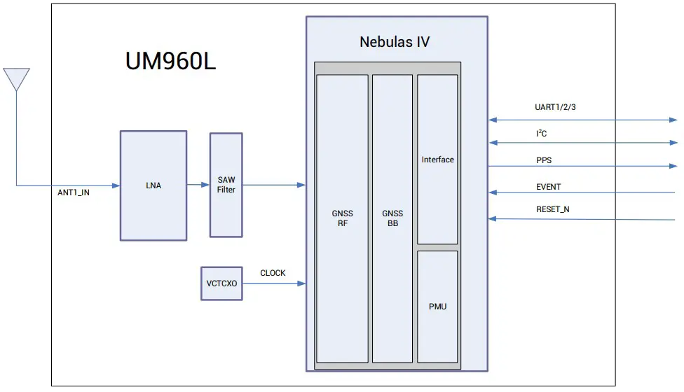
Figure 1-2 UM960L Block Diagram
- RF Part
The receiver gets filtered and enhanced GNSS signal from the antenna via a coaxial cable. The RF part converts the RF input signals into the IF signal, and converts IF analog signal into digital signals required for NebulasIVTM chip. - NebulasIVTM SoC
NebulasIVTM is UNICORECOMM’s new generation high precision GNSS SoC with 22 nm low power design, supporting all constellations, multiple frequencies and 1408 super channels. It integrates a 2 GHz dual CPU, a high speed floating point processor and an RTK co-processor, which can fulfill the high precision baseband processing and RTK positioning independently. - 1PPS
UM960L outputs 1 PPS with adjustable pulse width and polarity. - Event
UM960L provides 1 Event Mark Input with adjustable frequency and polarity. - Reset (RESET_N)
Active LOW, and the active time should be no less than 5 ms.
Hardware
Dimensions
Table 2-1 Dimensions
| Symbol | Min. (mm) | Typ. (mm) | Max. (mm) |
| A | 15.80 | 16.00 | 16.50 |
| B | 12.00 | 12.20 | 12.70 |
| C | 2.20 | 2.40 | 2.60 |
| D | 0.90 | 1.00 | 1.10 |
| E | 0.20 | 0.30 | 0.40 |
| F | 1.40 | 1.50 | 1.60 |
| G | 1.00 | 1.10 | 1.20 |
| H | 0.70 | 0.80 | 0.90 |
| N | 2.90 | 3.00 | 3.10 |
| P | 1.30 | 1.40 | 1.50 |
| R | 0.99 | 1.00 | 1.10 |
| X | 0.72 | 0.82 | 0.92 |
| φ | 0.99 | 1.00 | 1.10 |
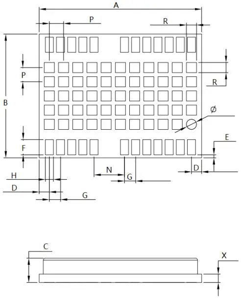
Figure 2-1 UM960L Mechanical Dimensions
Pin Definition
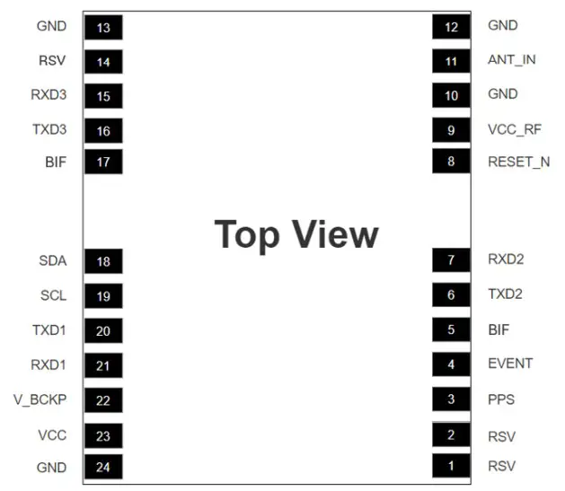
Figure 2-2 UM960L Pin Definition
Table 2-2 Pin Definition
| No. | Pin | I/O | Description |
| 1 | RSV | — | Reserved, must be floating; cannot connectground or power supply or peripheral I/O |
| 2 | RSV | — | Reserved, must be floating; cannot connectground or power supply or peripheral I/O |
| 3 | PPS | O | Pulse per second |
| 4 | EVENT | I | Event Mark |
| 5 | BIF | — | Built-in function; recommended to add a through-hole testing point and a 10 kΩ pull-up resistor; cannot connect ground or powersupply or peripheral I/O, but can be floating. |
| 6 | TXD2 | O | UART2 transmitting data |
| 7 | RXD2 | I | UART2 receiving data |
| 8 | RESET_N | I | System resetActive Low |
| 9 | VCC_RF1 | O | External LNA power supply |
| 10 | GND | — | Ground |
| 11 | ANT_IN | I | GNSS antenna signal input |
| 12 | GND | — | Ground |
| 13 | GND | — | Ground |
| 14 | RSV | — | Reserved, must be floating; cannot connectground or power supply or peripheral I/O |
| 15 | RXD3 | I | UART3 receiving data |
| 16 | TXD3 | O | UART3 transmitting data |
| 17 | BIF | — | Built-in function; recommended to add a through-hole testing point and a 10 kΩ pull-up resistor; cannot connect ground or powersupply or peripheral I/O, but can be floating. |
| 18 | SDA | I/O | I2C data |
| 19 | SCL | I/O | I2C clock |
| 20 | TXD1 | O | UART1 transmitting data |
| 21 | RXD1 | I | UART1 receiving data |
| 22 | V_BCKP2 | I | When the main power supply VCC is cut off, V_BCKP supplies power to RTC and relevant register. Level requirements: 2.0 V ~ 3.6 V, and the working current is less than 60 μA at25 °C. If you do not use the hot start function, connect V_BCKP to VCC. Do NOT connect it toground or leave it floating. |
| 23 | VCC | I | Supply voltage |
| 24 | GND | — | Ground |
- Not recommended to take VCC_RF as ANT_BIAS to feed the antenna See section 3.1 for more details.
- Not supported currently, and keep this pin floating.
Electrical Specifications
Absolute Maximum Ratings
Table 2-3 Absolute Maximum Ratings
| Parameter | Symbol | Min. | Max. | Unit |
| Power Supply (VCC) | VCC | -0.3 | 3.6 | V |
| Voltage Input | Vin | -0.3 | 3.6 | V |
| GNSS Antenna Signal Input | ANT_IN | -0.3 | 6 | V |
| RF Input PowerConsumption of Antenna | ANT_IN inputpower | +10 | dBm | |
| External LNA Power Supply | VCC_RF | -0.3 | 3.6 | V |
| VCC_RF Output Current | ICC_RF | 100 | mA | |
| Storage Temperature | Tstg | -55 | 95 | °C |
Operational Conditions
Table 2-4 Operational Conditions
| Parameter | Symbol | Min. | Typ. | Max. | Unit | Condition |
| Power Supply (VCC) | VCC | 3.0 | 3.3 | 3.6 | V | |
| Maximum Ripple Voltage | Vrpp | 0 | 50 | mV | ||
| Working Current3 | Iopr | 109 | 218 | mA | VCC = 3.3 V | |
| VCC_RF Output Voltage | VCC_RF | VCC-0.1 | V | |||
| VCC_RF Output Current | ICC_RF | 50 | mA | |||
| Operating Temperature | Topr | -40 | 85 | °C | ||
| Power Consumption | P | 410 | mW |
IO Threshold
Table 2-5 IO Threshold
| Parameter | Symbol | Min. | Typ. | Max. | Unit | Condition |
| Low Level InputVoltage | Vin_low | 0 | VCC × 0.2 | V | ||
| High Level InputVoltage | Vin_high | VCC × 0.7 | VCC + 0.2 | V | ||
| Low Level OutputVoltage | Vout_low | 0 | 0.45 | V | Iout= 4 mA | |
| High Level OutputVoltage | Vout_high | VCC – 0.45 | VCC | V | Iout =4 mA | |
Antenna Feature
Table 2-6 Antenna Feature
| Parameter | Symbol | Min. | Typ. | Max. | Unit | Condition |
| Optimum Input Gain | Gant | 18 | 30 | 36 | dB |
Since the product has capacitors inside, inrush current occurs during power-on. You should evaluate in the actual environment in order to check the effect of the supply voltage drop caused by inrush current in the system.
Hardware Design
Antenna Feed Design
UM960L just supports feeding the antennal from the outside of the module rather than the inside. It is recommended to use devices with high power and that can withstand high voltage. Gas discharge tube, varistor, TVS tube and other high-power protective devices may also be used in the power supply circuit to further protect the module from lighting strike and surge.
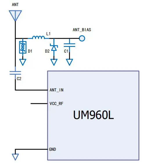
Figure 3-1 UM960L External Antenna Feed Reference Circuit
Remarks:
- L1: feed inductor, 68nH RF inductor in 0603 package is recommended;
- C1: decoupling capacitor, it is recommended to connect two capacitors of 100nF/100pF in parallel;
- C2: DC blocking capacitor, recommended 100pF capacitor;
- Not recommended to take VCC_RF as ANT_BIAS to feed the antenna (VCC_RF is not optimized for the anti-lighting strike and anti-surge due to the compact size of the module)
- D1: ESD diode, choose the ESD protection device that supports high frequency signals (above 2000 MHz)
- D2: TVS diode, choose the TVS diode with appropriate clamping specification according to the requirement of feed voltage and antenna voltage
Grounding and Heat Dissipation
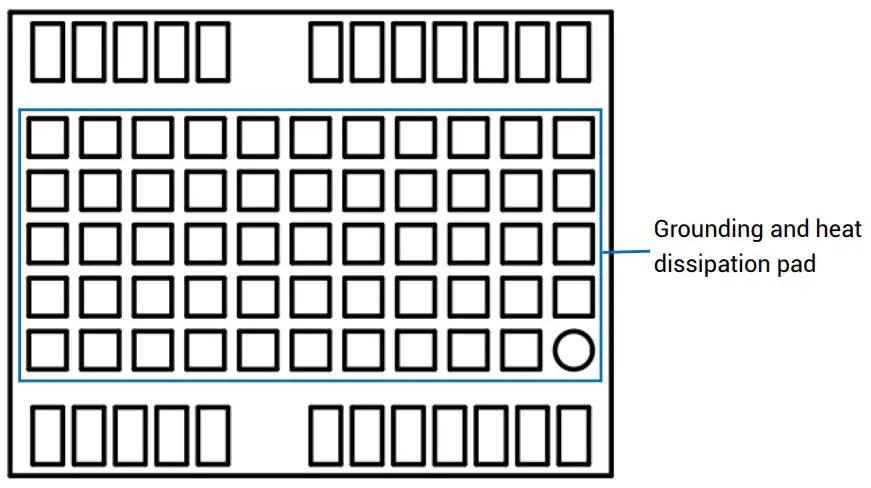
Figure 3-2 Grounding and Heat Dissipation Pad
The 55 pads in the rectangle in Figure 3-2 are for grounding and heat dissipation.
In the PCB design, they must connect to a large sized ground to strengthen the heat
dissipation.
Power-on and Power-off
VCC
- The VCC initial level when power-on is less than 0.4 V and it has good monotonicity. The voltages of undershoot and ringing are within 5% VCC.
- VCC power-on waveform: The time interval from 10% rising to 90% must be within 100 μs to 1 ms.
- Power-on time interval: The time interval between the VCC < 0.4 V (after power-off) to the next power-on must be larger than 500 ms.
V_BCKP
- The V_BCKP initial level when power-on is less than 0.4 V and it has good monotonicity. The voltages of undershoot and ringing are within 5% V_BCKP.
- V_BCKP power-on waveform: The time interval from 10% rising to 90% must be within 100 μs to 1 ms.
- Power-on time interval: The time interval between the V_BCKP < 0.4 V (after poweroff) to the next power-on must be larger than 500 ms.
Production Requirement
Recommended soldering temperature curve is as follows:
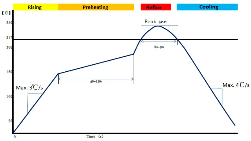
Figure 4-1 Soldering Temperature (Lead-free)
Temperature Rising Stage
- Rising slope: Max. 3 °C/s
- Rising temperature range: 50 °C to 150 °C
Preheating Stage
- Preheating time: 60 s to 120 s
- Preheating temperature range: 150 ° C to 180 °C
Reflux Stage
- Over melting temperature (217 °C) time: 40 s to 60 s
- Peak temperature for soldering: no higher than 245 ° C
Cooling Stage
- Cooling slope: Max. 4 °C/s
 In order to prevent falling off during soldering of the module, do not solder it on the back of the board during design, that is, better not go through soldering cycle twice.
- The setting of soldering temperature depends on many factors of the factory, such as board type, solder paste type, solder paste thickness, etc. Please also refer to the relevant IPC standards and indicators of solder paste.
- Since the lead soldering temperature is relatively low, if using this method, please give priority to other components on the board.
- The opening of the stencil needs to meet your design requirement and comply to the examine standards. The thickness of the stencil is recommended to be 0.15 mm.
Packaging
Label Description
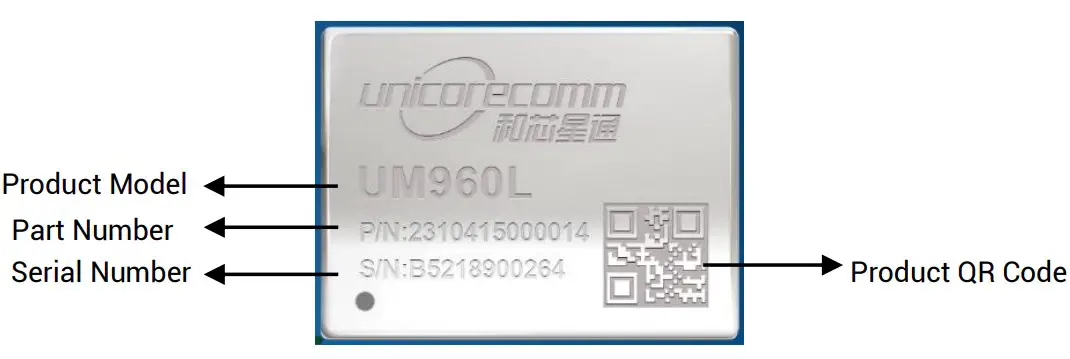
Figure 5-1 Label Description
Product Packaging
The UM960L module uses carrier tape and reel (suitable for mainstream surface mount devices), packaged in vacuum-sealed aluminum foil antistatic bags, with a desiccant inside to prevent moisture. When using reflow soldering process to solder modules, please strictly comply with IPC standard to conduct humidity control. As packaging materials such as the carrier tape can only withstand the temperature of 55 °C, modules shall be removed from the package during baking.
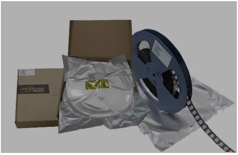
Figure 5-2 UM960L Package
Table 5-1 Package Description
| Item | Description |
| Module Number | 500 pieces/reel |
| Reel Size | Tray: 13″External diameter: 330 mm Internal diameter: 100 mm Width: 24 mmThickness: 2.0 mm |
| Carrier Tape | Space between (center-to-center distance): 20 mm |
The UM960L is rated at MSL level 3. Refer to the relevant IPC/JEDEC J-STD-033 standards for the package and operation requirements. You may access to the website www.jedec.org to get more information.
The shelf life of the UM960L module packaged in vacuum-sealed aluminum foil antistatic bags is one year.
 Unicore Communications, Inc.
F3, No.7, Fengxian East Road, Haidian, Beijing, P.R.China, 100094
www.unicorecomm.com
Phone: 86-10-69939800
Fax: 86-10-69939888
[email protected]


