![]() MADE IN THE USE
MADE IN THE USE
Quick Start Guide
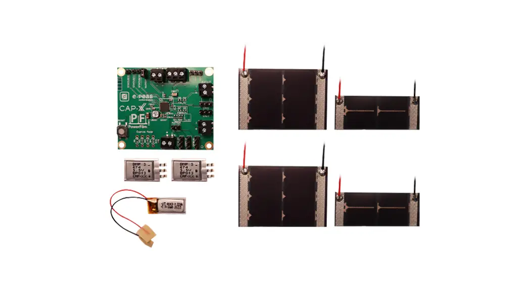
AEM10941 Solar Development Kit
Solar Development Kit with e-peas PMIC and CAP-XX Supercapacitors
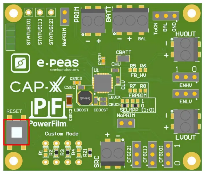
Step 1: AEM10941 Configuration
MPPT Ratio: Defined to 70%
Storage Element Voltages Protection: CFG2-CFG1-CFG0
| Configuration pins | Storage element threshold voltages I | LDOs output voltages I | Typical use | |||||
| 1 | 1 | 1 | 4.12 V | 3.67 V | 3.60 V | 3.3 V | 1.8 V | Li-ion battery |
| 1 | 1 | 0 | 4.12 V | 4.04 V | 3.60 V | 3.3 V | 1.8 V | Solid state battery |
| 1 | 0 | 1 | 4.12 V | 3.67 V | 3.01 V | 2.5 V | 1.8 V | Li-ion; NiMH battery |
| 1 | 0 | 0 | 2.70 V | 2.30 V | 2.20 V | 1.8 V | 1.2 V | Single-cell supercapacitor |
| 0 | 1 | 1 | ‘ 4.50 V | 3.67 V | 2.80 V | 2.5 V | 1.8 V | Dual-cell supercapacitor |
| 0 | 1 | 0 | 4.50 V | 3.92 V | 3.60 V | 3.3 V | 1.8 V | Dual-cell supercapacitor |
| 0 | 0 | 1 | 3.63 V | 3.10 V | 2.80 V | 2.5 V | 1.8 V | LiFePO4 battery |
| 0 | _ 0 | 0 | Custom mode – Programmable through R1 to R6 | 1.8 V | ||||
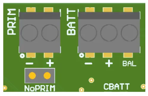
BAL Option: Select “CON” for dual-cells supercapacitor and “GND” for any other storage.
PRIM Option: Connect both jumpers “NoPRIM” or remove them if a primary battery is connected.
Define minimum voltage using R7 and R8.
- 100 kΩ RP < 500 kΩ

- R8=RP-R7
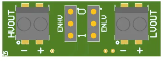
LDOs Output Voltages: ENHV [HVOUT] – ENLV [LVOUT]
| ENLV | ENHV | LV output | HV output |
| 1 | 1 | Enabled | Enabled |
| 1 | 0 | Enabled | Disabled |
| 0 | 1 | Disabled | Enabled |
| 0 | 0 | Disabled | Disabled |
Step 2: Connect the storage element or solder a CAP-XX supercapacitor on the bottom layer (refer to the table on the following page)
Step 3: Connect the Load(s) to HVOUT / LVOUT
Step 4: Connect the PowerFilm Photovoltaic module to SRC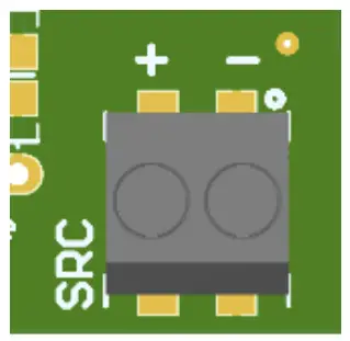 Step 5: Set up complete! See User Guide for additional details and advanced configurations.
| Package name | Footprint | Comment |
| DMF/DMT | 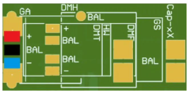 | Use Jumper to Connect “BAL”to “ToCN” |
| DMH | 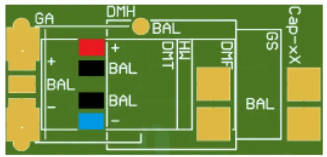 | Use Jumper to Connect “BAL” to “ToCN” This model is not delivered in this evaluation kit |
| A | 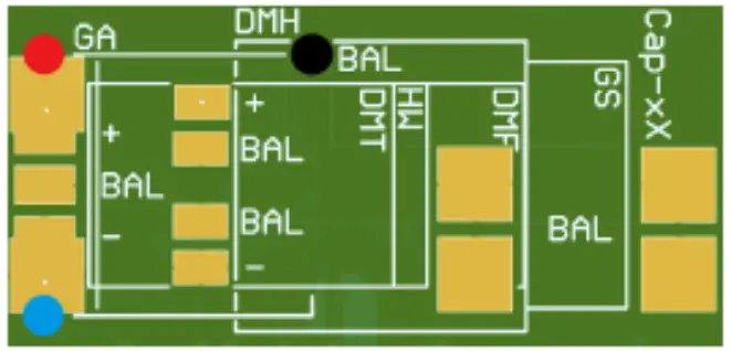 | Use Jumper to Connect “BAL” to “ToCN” This model is not delivered in this evaluation kit |
| Dual cell S/W | 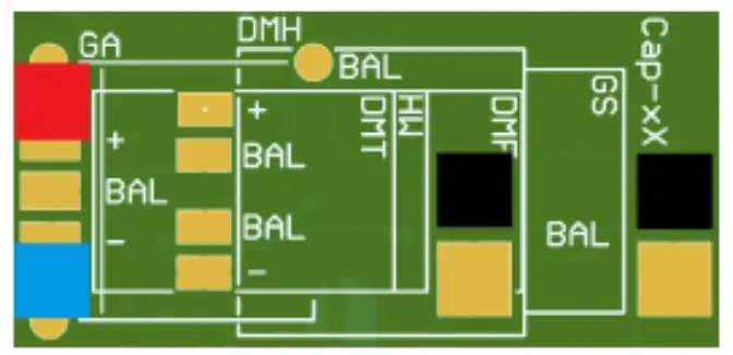 | Use Jumper to Connect “BAL” to “ToCN” This model is not delivered in this evaluation kit |
| Single cell S/W | 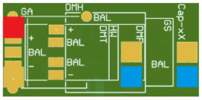 | Use Jumper to Connect “BAL” to “GND” To fit on the board, the supercapacitor must be flipped on its back This model is not delivered in this evaluation kit |
Table 7: Footprint description
This footprint is available on the inferior face of the PCB. The red colour represents the positive voltage, the blue is the ground and the black is to be connected to the balancing pin. Those three potentials are available on the screw terminal on the top side.
PowerFilm, Inc. • 1287 XE Place • Ames, IA 50014 USA • www.powerfilmsolar.com • 515-292-7606


