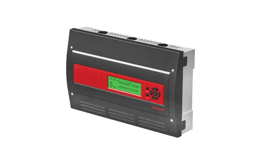
Honeywell AQ25244B Universal Injection / Mixing Boiler Reset Control Panel Installation Guide
System commissioning date: _________________________
Customer: _______________________________________
Building address: _________________________________
INSTRUCTIONS:
Fill in the details of the equipment connected to the control module and the zoning module:
- A Low voltage control module wiring
- B Line voltage Boiler pump, DHW pump, and AUX output
- C Low voltage zone thermostats
- D Low voltage zone valves with end switches
- E Review and set DIP switch settings – once DIP switches for the zoning module (AQ25744B) have been set, complete the “Installer Settings” diagram by filling in the circles to indicate the DIP switch position set during installation
File this with other installation records for equipment used on this installation.
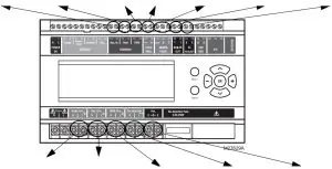
A Boiler Control Module – Low Voltage
| Terminal # | 11-12 | 13-14 | 15-16 | 17-18 | 19-21 | 22-23 | 24-25 |
| Terminal ID | Aux. In | Heat | DHW | + 10Vdc – | COM O C | Boiler | Aux. Out |
| Input/ Output Description | Input | Input | Input | Output | Output | Output | Output |
| Powered | Powered | Powered | Powered | Powered | Dry Contact | Dry Contact | |
| Warning: Do not apply power to these terminals | |||||||
| Function | Installer defined | Heat Demand | DHW Demand | Modulating Signal | Floating Valve Signal | Boiler Demand | Installer defined |
| Equipment | |||||||
| Manufacturer | |||||||
| Model # | |||||||
| Serial # | |||||||
| Date Code | |||||||
| Notes | |||||||

B Boiler pump, Secondary pump, DHW, and AUX Device
| Terminal ID | Boiler | Sec | DHW | Var. Injection | Aux |
| Input/ Output Description | Output | Output | Output | Output | Output |
| Powered | Powered | Powered | Powered | Dry Contact | |
| Function | Boiler loop control | Secondary loop control | DHW loop control | Injection pump control | Installer defined |
| Equipment | |||||
| Manufacturer | |||||
| Model # | |||||
| Amp Draw | |||||
| Date Code | |||||
| Notes |
C Zoning Thermostats
| Terminal # | 5-6 | 7-8 | 9-10 | 11-12 |
| Terminal ID | TH1 | TH2 | TH3 | TH4 |
| Function | Zone call for heat | |||
| Equipment | ||||
| Manufacturer | ||||
| Model # | ||||
| Date Code | ||||
| Notes | ||||
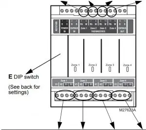
D Zoning Valves
| Terminal ID | Zone 1 | Zone 2 | Zone 3 | Zone 4 |
| Function | Zone control | |||
| Equipment | Valve | Valve | Valve | Valve |
| Manufacturer | ||||
| Model # | ||||
| Power draw VA | ||||
| Notes | ||||
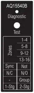
E Zoning Module DIP Switch Settings
M23720A
Factory Setting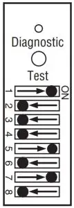
Installer Setting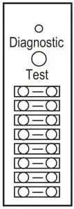
M23715
Fill in the circle to indicate position of DIP switch.
| DIP Number | Description |
| 1 | Zone Address Slide the DIP switch to the right-hand (ON) position to indicate which group of zones this is. The correct DIP switch settings for each zone module are: •Fourth Zone (13-16) Module: 4 = ON position; 1, 2, and 3 = OFF position |
| 2 | |
| 3 | |
| 4 | |
| 5 | • If set to SYNC, zone synchronization is enabled. •If set to NOT, zone synchronization is disabled. |
| 6 | •If zone valves are normally closed (N.C.), set the NC/NO DIP switch to the OFF position. •If zone valves are normally open (N.O.), set the NC/NO DIP switch to the ON position. |
| 7 | • If set to Group (ON position) the zone outputs are energized with the AUX pump. • If set to – (OFF position), the AUX Pump contacts are not affected by activity on these zones. |
| 8 | • If set to 2-Stg (ON position), then 2-stage operation is activated on thermostat inputs. The zoning module operates as two 2-stage zones or 3 zones (one 2-stage and two 1-stage). • If set to 1-Stg (OFF position), then operates as four 1- stage zones. |
NOTE: When wiring zone valves with end switches, note the transformer’s VA: If low voltage zone valves with end switches are used for zone control, make sure the selected zone valves do not draw more power (VA) than the 38 VA capacity of the AQ10X38 transformer supplied with the AQ252 Control Panel. This integral transformer has enough power to operate 4 motorized zone valves (such as Honeywell V8043E valves or 4 valves using lowamperage draw, heat motor actuators, such as Honeywell MV100 actuators), plus power the electronics of the AQ252’s Control Module and up to 16 AQ1000 thermostats. If zone valves with highamperage draw, heat motor actuators are used (such as Taco 500 series zone valves), additional 24 Vac transformer capacity will need to be wired to the Zoning Module to power the valves. Refer to theInstallation Instructions for AQ255/AQ257 Expansion Zoning Panels (Form No. 69-1981) for recommended wiring of additional low voltage VA capacity to AQ2000 Series Zoning Modules.
![]() CAUTION
CAUTION
Equipment Damage Hazard.
Can damage internal circuitry of Zoning Module. The ES1 and ES2 terminals of the AQ15740B Zoning Module are powered terminals and must only be connected to a set of dry contacts, such as a zone valve motor’s end switch. If power is applied to these contacts (for example, by running line voltage through the zone valves’ end switches to bring on a circulator feeding those valves), the internal circuitry of the Zoning Module will be damaged, in which case the warranty for this product will be voided.
EQUIPMENT SETTINGS
The Installer Menu is used to establish and modify the system’s equipment and option settings. These include equipment settings for boiler operation, DHW management, zoning, auxiliary input/output operation, and option settings such as pump/valve exercise, and freeze protection.
Use Table 1 to record the equipment settings for this installation.
To record the equipment and option settings:
- A Press the Home button to return to the Home Page display.
- B Press and hold the OK button for 3 seconds until the message, INSTALLER MODE – ARE YOU SURE?, displays.
- C Select YES, then press and release the OK button to display the Installer Menu.
- D Select the Equipment Setup sub-menu.
- E Record the configured settings in Table 1.
- F Exit Installer mode by selecting the Installer Exit menu option.
Table 1. Installer Menu – Equipment Setup Sub-menu.
| EQUIPMENT SETUP SUB-MENU | ||||
| Sub-Menu and Option | Range | Factory Default | Equipment Settings Used | |
| BOILER SETTINGS | ||||
| HIGH LIMIT | 120°F to 225°F (49°C to 107°C) | 190°F (88°C) | ||
| LOW LIMIT | 60°F to 180°F (15°C to 82°C) | 150°F | ||
| BOILER DIFF | 2°F to 41°F (1°C to 23°C) / AUTO | AUTO | ||
| W.W.S.D. | – – a 35°F to 100°F (2°C to 38°C) | 70°F (21°C) | ||
| RESET | OUTDOOR / LOAD / NONE | OUTDOOR | ||
| OUTDOOR LOW | -60°F to 32°F (-51°C to 0°C) | 10°F (-12°C) | ||
| BOILER DSGN | 80°F to 210°F (27°C to 99°C) | 180°F (82°C) | ||
| MIN. RETURN | – – / 80°F to 180°F (27°C to 82°C) | 140°F (60°C) | ||
| BOILER OPERATION | ||||
| CYCLES/HOUR | 2 to 6 | 4 | ||
| FIRE DELAY | 0 seconds to 3 minutes (in 5 second increments) | 10 (seconds) | ||
| PURGE TIME | OFF, 10 seconds to 30 minutes (in 10 second increments) | 30 (seconds) | ||
| EXERCISE | YES / NO | YES | ||
| FREEZE PROT | YES / NO | YES | ||
| 10V MOD. SELECT | ||||
| 10V MOD | 0-10V / 2-10V | 0-10V | ||
| USAGE | NONE / MIX. INJ. / BOILER | NONE | ||
| SECONDARY LOOP | ||||
| MIX HIGH | – – 80°F to 210°F (27°C to 99°C) | 140°F (60°C) | ||
| MIX LOW | – – 35°F to 150°F (2°C to 66°C) | – – (disabled) | ||
| MIX DESIGN | 70ºF to 210ºF (21ºC to 99ºC) | 120°F (49°C) | ||
| INJECT. | ENABLE / DISABLE | ENABLE | ||
| MIX.VLV | ENABLE / DISABLE | DISABLE | ||
| MIX.V.TTO | 5 to 230 seconds (in 5 second increments) | 160 (seconds) | ||
| MIX.V.ACT | DIRECT / REVRSE | DIRECT | ||
| MIX DEVICE | FLOAT / INJ / 10V | 10V | ||
| DOMEST.HOT WATER | ||||
| DHW | ENABLE / DISABLE | ENABLE | ||
| DHW PRIO | YES / NO | NO | ||
| PRIO.OVER. | YES / NO | YES | ||
| DHW DEVICE | PUMP / VALVE | PUMP | ||
| DHW VLV.OP | 0 – 230 seconds(in 5 second increments) | 15(seconds) | ||
| DHW PURGE | YES / NO | YES | ||
| DHW SENSOR | YES / NO | NO | ||
| DHW SETPOINT | – – 60°F to 160°F (16°C to 71°C) | 140°F (60°C) | ||
| DHW DIFF | – – 5°F to 40°F (2.5°C to 22°C) | 20°F (-7°C) | ||
| DHW VACANCY | – – [41°F + DHW DIFF] to 160°F ([5°C + DHW DIFF] to 71°C) | 45°F (7°C) | ||
| ZONING | ||||
| HEAT DMND | RESET / SETPT | RESET | ||
| HT DMND PRIO | YES / NO | NO | ||
| PRIO.OVER | YES / NO | NO | ||
| ZONING VALVES TIME TO OPEN | 5 – 230 (seconds) | 15 (seconds) | ||
| PRI/SEC | PRI / SEC | SEC | ||
| AUXILIARY I/O | ||||
| AUX.IN(optional) | SETBACK / VACANCY / EM. SHUT / NONE | SETBACK | ||
| AUX.OUT(optional) | BOILER / SETBACK / ZONE OP. / ALARM / AUX.IN / DHW IN / HEAT IN / HT DMND / COOL / NONE | BOILER | ||
| AUX.PUMP(optional) | BOILER / GROUP / OCC / BYPASS / FAN / NONE / AUX.IN / DHW IN /HEAT IN / HT DMND | BOILER | ||
| A/C SETTINGS | ||||
| CYCLES/HOUR | 2 / 3 / 4 / 5 / 6 | 4 | ||
| MIN.OFF TIME | 2 to 10 (minutes) | 5M | ||
| C.W.S.D. | – -32°F to 100°F (0°C to 38°C) | 65°F (18°C) | ||
| FAN MODE | AUTO / ON | AUTO | ||
| A/C EQUIP CONFIG | ||||
| ZONE | A-1 to D-16 | A-1 | ||
| A/C UNIT | NONE / 1 | 1 | ||
| COOLING | ENABLE / DISABLE | ENABLE | ||
| ENVIRACOM (not used – reserved for future use) | ||||
Any entry of two dashes (- -) indicates that the option is disabled or not used.
Automation and Control Solutions
Honeywell International Inc.
1985 Douglas Drive North
Golden Valley, MN 55422
customer.honeywell.com


