VTS RH+T-SENS-D-MODRTU Compact Floor-Mounted Air Handling Units Instruction Manual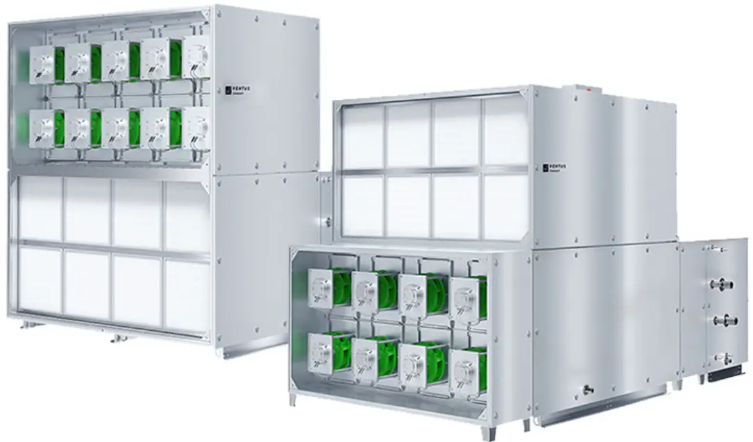
Introduction
This document describes functionality of air relative humidity and temperature transducer based on integrated Sensirion SHT31-DIS-B sensor, equipped with RS485 interface using MODBUS RTU protocol and 0-5V / 0-10V analogue output.
NOTES:
- Read this document carefully before attempting to start up the device!
- The device must be installed by qualified staff only.
Functions of the device
- relative humidity measurement
- 0-5V or 0-10V analogue output (hardware selectable range) proportional to relative humidity
- 3 status LEDs
- RS485 serial interface for remote management (setup and reading of measurement values)
- MODBUS RTU protocol
- integrated terminating resistor 120Ω
- communication in HALF DUPLEX mode
- hardware/software configurable address in the range 1-247
- hardware configurable communication baud rate: 19200, 9600, 4800, 2400
- software configurable communication baud rate: 115200, 57600, 38400, 19200, 9600, 4800, 2400
Design Features
The main function of the RH&T transmitter is to measure air relative humidity and
temperature using an integrated Sensirion SHT31-DIS-B sensor. The measurement result, as well as the sensor missing/error status, is processed by the built-in microprocessor and then made available on the RS-485 bus via registers of the MODBUS RTU protocol. Additionally, the measurement result air relative humidity is available as analog signal on the 0-5V / 0-10V voltage output.
Technical data
General parameters of the transducer
Power supply
- DC voltage: DC 20-30 V (nom. DC 24 V)
- AC voltage: AC 20-28 V (nom. AC 24 V)
Current consumption
- typical: TBD
- max: TBD
LED indicators
- Signal connection
- Screw terminals in 5mm pitch
- (wire diameter ≤ 2.5mm)
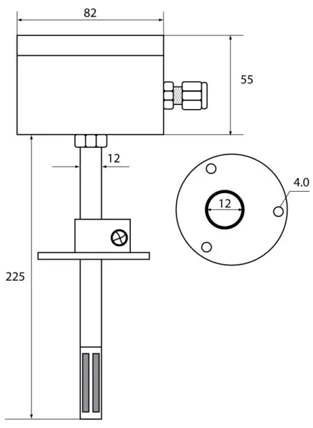
Housing dimensions
- without sampling mast: 80x82x55mm
- with sampling mast: 80x82x280mm
| Weight | 230 g |
| Work environment | Dust-free, air, neutral gases |
| Working temperature | 0ºC ÷ 50ºC |
Parameters of humidity measurement
| Sensor model | SHT31-DIS-B |
| Measurement range | 0÷ 100% RH |
| Resolution | 14.5 bit (0.01% RH) |
| Measurement accuracy (@ T=25ºC) | |
| – in the range 0 ÷ 90% RH | ± 2% RH |
| – in the remaining measurement range | ± 3% RH |
| Hysteresis | ± 0.8% RH |
| Sampling frequency | 1 Hz |
- The prerequisite for obtaining the given response times is an air flow > 1m/s; the response time indicated is equal to one time constant corresponding to 63 % of the steady value
Parameters of temperatures measurement
| Sensor model | SHT31-DIS-B |
| Measurement range | 0ºC ÷ 90ºC |
| Resolution | 14.5 bit (0.01ºC) |
| Measurement accuracy (over entire measuring range) | ± 0.25ºC |
| Sampling frequency | 1 Hz |
| Response time 1) | 2 s |
Response time 1)
- The prerequisite for obtaining the given response times is an air flow > 1m/s; the response time indicated is equal to one time constant corresponding to 63 % of the steady value
Parameters of analogue output
| Output type | voltage |
| Output range | 0-5 V or 0-10 V |
| Resolution | 11.5 bit |
| in [mV] for the range 0-10 V | 3.2mV~ |
| in [mV] for the range 0-5 V | 1.6mV~ |
| Loading capacity | RL > 1 kΩ |
| Refreshing period | 1 s |
Parameters of serial interface
| Transmission Adapter | RS-485 | |
| Communication protocol | MODBUS RTU | |
| Transmission type | HALF DUPLEX | |
| Communication baud | 2400 / 4800 / 9600 / 19200 / 38400 / 57600 / 115200 Baud/s | |
| Integrated resistor terminating the RS-485 bus | 120 Ω | |
Installation
Safety
- The device must be installed by qualified staff only!
- All connections must be made in accordance with wiring diagrams shown in this document!
- Check all electrical connections prior to commissioning!
Device design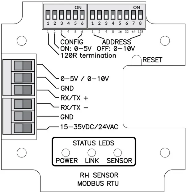
Description of terminals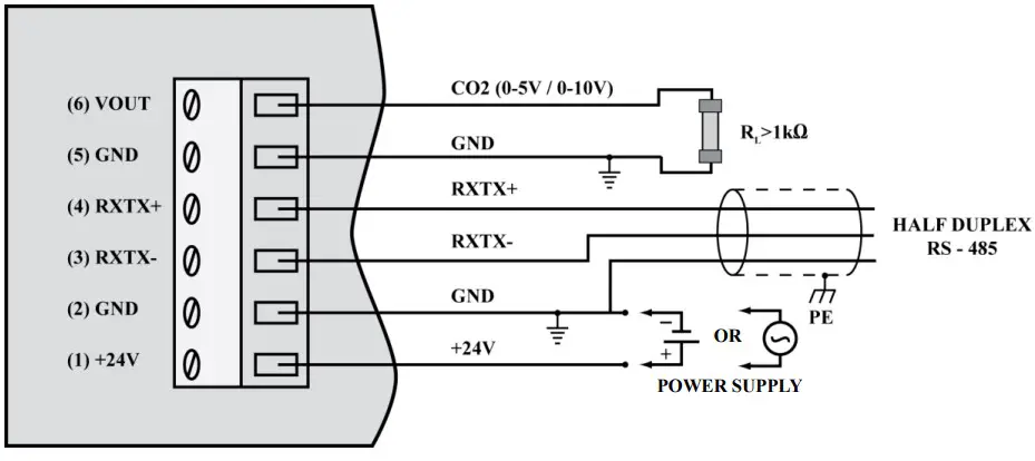
Notes:
- The RXTX+ and RXTX- signals must be connected to the A and B lines of the MODBUS bus respectively.
- The analogue output returns following voltage values:
whereas the concentration value can be calculated basing on the voltage value form using the following formula:
where:
VOLTAGERANGE = 5V or 10V (0-5V or 0-10V set on the configuration DIP-switch 2 – see section 3.4)
Exemplary values are shown in the table below:
| Relative humidity [%] | Voltage range = 5 V | Voltage range = 10V |
| 0 | 0.0V~ | 0.0V~ |
| 25 | 1.0V~ | 2.0V~ |
| 50 | 2.5V | 5.0V |
| 75 | 3.75V~ | 7.5V~ |
| 100 | 5.0V~ | 10.0V~ |
Configuration of MODBUS bus, serial port and analogue output
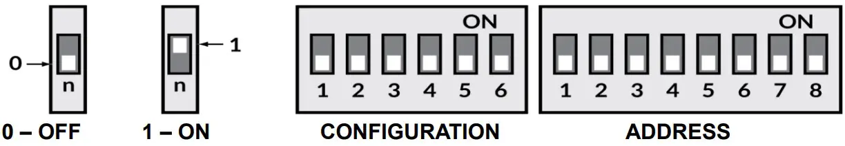
The purpose of the consecutive switches of the left DIP-switch is as follows (default values are in bold)
| 1 | 2 | 3 | 4 | 5 | 6 | Effect | |
| ON | Terminating resistor 120R switched on | ||||||
| OFF | Terminating resistor 120R switched off | ||||||
| ON | Analogue output range 0-5V | ||||||
| OFF | Analogue output range 0-10V | ||||||
| ON | ON | Use BAUDRATE and PAR from the software configuration | |||||
| ON | OFF | PAR – parity check (1 STOP bit) | |||||
| OFF | ON | PAR – no parity check (2 STOP bits) | |||||
| OFF | OFF | PAR – no parity check (1 STOP bit) | |||||
| ON | ON | BAUDRATE=2400 | |||||
| ON | OFF | BAUDRATE=4800 | |||||
| OFF | ON | BAUDRATE=9600 | |||||
| OFF | OFF | BAUDRATE=19200 |
The device address on the MODBUS bus is set using the right DIP-switch:
| 1 | 2 | 3 | 4 | 5 | 6 | 7 | 8 | Effect |
| ON | Address = address + 1 | |||||||
| ON | Address = address + 2 | |||||||
| ON | Address = address + 4 | |||||||
| ON | Address = address + 8 | |||||||
| ON | Address = address + 16 | |||||||
| ON | Address = address + 32 | |||||||
| ON | Address = address + 64 | |||||||
| ON | Address = address + 128 |
Note: the configuration set by the means of DIP-switches is read once after device restart (after switching on the power or pressing the RESET button). For this reason, if the DIP switch settings are changed during operation, then after changing the settings, it is necessary to restart the device by pressing the RESET button or temporarily unplugging the power supply
LED indicators
LED POWER
| No. | Description | Color / mode of light |
| 1 | Power supply present | Red – flashing 1000 ms / 1000 ms |
LED LINK
| No. | Description | Color / mode of light |
| 1 | Data transmission on the bus | Green – continuous light / irregular flashing |
| 2 | No transmission | LED off |
LED SENSO
| No. | Description | Color / mode of light |
| 1 | 0 – 19.9% RH | Yellow – continuous light |
| 2 | 20– 79.0% RH | Green – continuous light |
| 3 | 80– 100% RH | Red – continuous light |
| 4 | Sensor missing or other error | Red – flashing 100 ms / 600 ms |
Recommendations for installation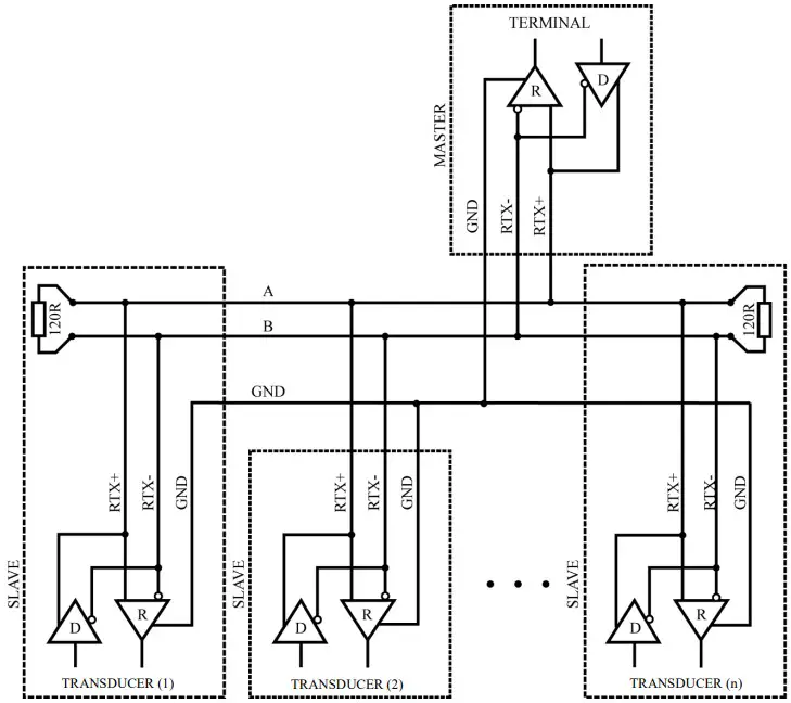
It is recommended that devices on the MODBUS (RS485) are connected in a daisy-chain configuration, whereby 120R terminating resistors should be connected between A and B lines of the bus at both ends of the chain (close to the outer devices). This resistor is builtin in the RH&T-SENS-D-MODBRTU transducer and can be switched on using the no. 1 switch on the configuration DIP-switch (see section 3.4).
Moreover, shielded cables should be used when the device is operated in high interference environments and the shield should be connected to the nearest PE point on the power supply side
MODBUS protocol
Register map
| Registerno. | R/W | Name | Values | Notes |
| 0x0000 | R | RH_REG | 0 ÷ 1000 | Relative humidity (1=0.1%; 1000=100%) |
| 0x0001 | R | TEMP_REG | -4000 ÷ 12380 | Temperature [ºC] (1=0.01ºC) with sing |
| 0x0002 | R | TEST_VAL_REG | 1000 (0x3E8) | Test value – to verify the correctness ofregister readings |
| 0x0003 | RW | PASS_REG | 1234 (0x04D2) | password register |
| 0x0004 | RW | COMMAND_REG | 1 / 2 / 3 / 4 / 5 /6 | command register |
| 0x0005 | RW | PARAM_REG | Refer tocommand table | parameter register |
| 0x0006 | R | — | 0 | reserved |
| 0x0007 | R | — | 0 | reserved |
| 0x0008 | R | — | 0 | reserved |
| 0x0009 | R | — | 0 | reserved |
| 0x000A | R | STATUS_REG | 0 / 1 / 2 | Status register (0: NO SENSOR; 1: SENSOR OK,2: ERROR) |
| 0x000B | R | DEV_ID_REG | 0xC100 | Device identification |
| 0x000C | R | SOFT_VER_REG | 0 – 0x9999 | Software version(e.g. 0x3210 means software 3.21a) |
Command table:
| Command no. | Function | Parameters |
| 1 | Set device address | 1-247 (1 – default value) |
| 2 | Set the baud rate | 24 – 2400 bit/s48 – 4800 bit/s96 – 9600 bit/s192 – 19200 bit/s = default value 384 – 38400 bit/s576 – 57600 bit/s1152 – 115200 bit/s |
| 3 | Set parity bits | 0 – NO PARITY, no parity bit (default value) 1 – EVEN PARITY, even parity bit2 – ODD PARITY, odd parity bit |
| 4 | Set stop bits | 1 – 1x STOP, 1 stop bit (default value) 2 – 2x STOP, 2 stop bits |
| 6 | Device reset | 1 – software reset of the device2 – software reset of sensor module |
Notes:
- Reading registers from addresses not listed in this table results in 0x02 exception.
- Specifying an incorrect or out-of-range parameter value results in entering the value 0xEEEE into the command register.
- The device is configured by writing three registers (password / command / parameter) at the same time using the 0x10 function with the corresponding values
- according to the command table, or by writing single registers (using 0x06 or 0x10 function) with the latter writing of a (valid) password causing the execution of the command.
- During a single password entry (both with function 0x06 and 0x10) in case of a password match, the correctness of information in command and parameter registers is checked and if correct, the command is executed
DEV_ID_REG (addr=11=0x000B) – read only
| Bit no. | 15 | 14 | 13 | 12 | 11 | 10 | 9 | 8 | 7 | 6 | 5 | 4 | 3 | 2 | 1 | 0 |
| name | DEV[4..0] | HV[1..0] | OPTIONS[4..0] | 0 | 0 | T[1..0] | ||||||||||
This register is used to store device ID. Meaning of bits: DEV[4..0] = b11000 – fixed value meaning “air parameter sensors” HV[1..0] – value 0..3 – hardware version OPTIONS[4..0] – values 0..31 – device type
- b01000 – RH&T transducer with SHT31-DIS-B sensor
- T[1..0] – value 0..3 – type
- 0 – duct type
- 1 – room type
- 2, 3 – reserved
RH&T duct sensor in basic hardware version returns the value b1100000010000000=0xC080.
SOFT_VER_REG (addr=12=0x000C) – read only
| Bit no. | 15 | 14 | 13 | 12 | 11 | 10 | 9 | 8 | 7 | 6 | 5 | 4 | 3 | 2 | 1 | 0 |
| name | N[3..0] | A[3..0] | B[3..0] | REV[3..0] | ||||||||||||
Software version is represented as a sting of 4 characters: N.ABrev where
N, A, B are digits in the the 0..9 range rev (with values 0..9) is a letter in the range ‘a’…’j’.
Examples: 0x0000 represents software version: 0.00a; 0x4321 → 4.32b ; 0x2345 → 2.34f
Protocol functions
| CODE | Name |
| 0x03 (dec 3) | Reading N x 16-bit registers |
| 0x06 (dec 6) | Writing single 16-bit registers |
| 0x10 (dec 16) | Writing N x 16-bit registers |
Reading the contents of a group of output registers (0x03)
Command format:
| Description | Size [Bytes] | Values | Notes |
| Address | 1 | 1 – 247 | |
| Function code | 1 | 0x03 | |
| Data block address | 2 | 0x0000 – 0xFFFF | |
| Number of registers (N) | 2 | 1 – 125 | |
| Check sum CRC | 2 | 0x0000 – 0xFFFF | See section 4.4 |
Response format:
| Description | Size [Bytes] | Values | Notes |
| Address | 1 | 1 – 247 | |
| Function code | 1 | 0x03 | |
| Byte counter | 1 | 2 * N | |
| Register values | 2 * N | Acc. to register map | |
| Check sum CRC | 2 | 0x0000 – 0xFFFF | See section 4.4 |
Error format:
| Description | Size [Bytes] | Values | Notes |
| Address | 1 | 1 – 247 | |
| Function code | 1 | 0x83 | |
| Error code | 1 | 1 – 4 | See section 4.2.4 |
| Check sum CRC | 2 | 0x0000 – 0xFFFF | See section 4.4 |
Writing single 16-bit registers (0x06) Command format:
| Description | Size [Bytes] | Values | Notes |
| Address | 1 | 1 – 247 | |
| Function code | 1 | 0x06 | |
| Register address | 2 | 0x0000 – 0xFFFF | |
| Value to be stored | 2 | 0x0000 – 0xFFFF | |
| Check sum CRC | 2 | 0x0000 – 0xFFFF | See section 4.4 |
Response format:
| Description | Size [Bytes] | Values | Notes |
| Address | 1 | 1 – 247 | |
| Function code | 1 | 0x06 | |
| Register address | 2 | 0x0000 – 0xFFFF | |
| Value to be stored | 2 | 0x0000 – 0xFFFF | |
| Check sum CRC | 2 | 0x0000 – 0xFFFF | See section 4.4 |
Error format:
| Description | Size [Bytes] | Values | Notes |
| Address | 1 | 1 – 247 | |
| Function code | 1 | 0x86 | |
| Error code | 1 | 1 – 4 | See section 4.2.4 |
| CRC check sum | 2 | 0x0000 – 0xFFFF | See section 4.4 |
Writing a group of output registers (0x10) Command format:
| Description | Size [Bytes] | Values | Notes |
| Address | 1 | 1 – 247 | |
| Function code | 1 | 0x10 | |
| Data block address | 2 | 0x0000 – 0xFFFF | |
| Liczba rejestrów (N) | 2 | 1 – 123 | |
| Byte counter | 1 | 2 * N | |
| Values to be stored | 2 * N | 0x0000 – 0xFFFF | |
| CRC check sum | 2 | 0x0000 – 0xFFFF | See section 4.4 |
Response format:
| Description | Size [Bytes] | Values | Notes |
| Address | 1 | 1 – 247 | |
| Function code | 1 | 0x10 | |
| Data block address | 2 | 0x0000 – 0xFFFF | |
| Number of registers (N) | 2 | 1 – 123 | |
| CRC check sum | 2 | 0x0000 – 0xFFFF | See section 4.4 |
Error format:
| Description | Size [Bytes] | Values | Notes |
| Address | 1 | 1 – 247 | |
| Function code | 1 | 0x90 | |
| Error code | 1 | 1 – 4 | See section 4.2.4 |
| CRC check sum | 2 | 0x0000 – 0xFFFF | See section 4.4 |
Description of errors
| CODE | Name |
| 0x01 | Invalid function |
| 0x02 | Invalid data range / address |
| 0x03 | Invalid data value |
| 0x04 | SLAVE device error |
Data format
Character / byte format
The following figure shows the format of a byte transmitted in the MODBUS RTU protocol. Each transmitted character has 10 or 11 bits, which are sent in order from the least significant to the most significant.
With even / odd parity check
| START | 1 | 2 | 3 | 4 | 5 | 6 | 7 | 8 | PAR | STOP |
Without parity check (1 or 2 stop bits):
| START | 1 | 2 | 3 | 4 | 5 | 6 | 7 | 8 | STOP | (STOP) |
Order of bytes in 16-bit data fields in a transmission frame
The following figure shows the byte order of the 16-bit data fields. For 16-bit data fields, the correct byte order is that the older byte is transmitted first, then the younger byte (HI→LO – BIG ENDIAN), while for the CRC field the younger byte is transmitted first, then the older byte (LO→ HI – LITTLE ENDIAN).
| DATA | CHECK SUM | ||||||||
| REG-0 (16bit) | REG-1 (16 bit) | … | REG-N (16bit) | CRC (16bit) | |||||
| HI | LO | HI | LO | HI | LO | LO | HI | ||
CRC check sum
WORD CRC16 (const BYTE *nData, WORD wLength) static const WORD wCRCTable[] = { 0x0000, 0xC0C1, 0xC181, 0x0140, 0xC301, 0x03C0, 0x0280, 0xC241, 0xC601, 0x06C0, 0x0780, 0xC741, 0x0500, 0xC5C1, 0xC481, 0x0440, 0xCC01, 0x0CC0, 0x0D80, 0xCD41, 0x0F00, 0xCFC1, 0xCE81, 0x0E40, 0x0A00, 0xCAC1, 0xCB81, 0x0B40, 0xC901, 0x09C0, 0x0880, 0xC841, 0xD801, 0x18C0, 0x1980, 0xD941, 0x1B00, 0xDBC1, 0xDA81, 0x1A40, 0x1E00, 0xDEC1, 0xDF81, 0x1F40, 0xDD01, 0x1DC0, 0x1C80, 0xDC41, 0x1400, 0xD4C1, 0xD581, 0x1540, 0xD701, 0x17C0, 0x1680, 0xD641, 0xD201, 0x12C0, 0x1380, 0xD341, 0x1100, 0xD1C1, 0xD081, 0x1040, 0xF001, 0x30C0, 0x3180, 0xF141, 0x3300, 0xF3C1, 0xF281, 0x3240, 0x3600, 0xF6C1, 0xF781, 0x3740, 0xF501, 0x35C0, 0x3480, 0xF441, 0x3C00, 0xFCC1, 0xFD81, 0x3D40, 0xFF01, 0x3FC0, 0x3E80, 0xFE41, 0xFA01, 0x3AC0, 0x3B80, 0xFB41, 0x3900, 0xF9C1, 0xF881, 0x3840, 0x2800, 0xE8C1, 0xE981, 0x2940, 0xEB01, 0x2BC0, 0x2A80, 0xEA41, 0xEE01, 0x2EC0, 0x2F80, 0xEF41, 0x2D00, 0xEDC1, 0xEC81, 0x2C40, 0xE401, 0x24C0, 0x2580, 0xE541, 0x2700, 0xE7C1, 0xE681, 0x2640, 0x2200, 0xE2C1, 0xE381, 0x2340, 0xE101, 0x21C0, 0x2080, 0xE041, 0xA001, 0x60C0, 0x6180, 0xA141, 0x6300, 0xA3C1, 0xA281, 0x6240, 0x6600, 0xA6C1, 0xA781, 0x6740, 0xA501, 0x65C0, 0x6480, 0xA441, 0x6C00, 0xACC1, 0xAD81, 0x6D40, 0xAF01, 0x6FC0, 0x6E80, 0xAE41, 0xAA01, 0x6AC0, 0x6B80, 0xAB41, 0x6900, 0xA9C1, 0xA881, 0x6840, 0x7800, 0xB8C1, 0xB981, 0x7940, 0xBB01, 0x7BC0, 0x7A80, 0xBA41, 0xBE01, 0x7EC0, 0x7F80, 0xBF41, 0x7D00, 0xBDC1, 0xBC81, 0x7C40, 0xB401, 0x74C0, 0x7580, 0xB541, 0x7700, 0xB7C1, 0xB681, 0x7640, 0x7200, 0xB2C1, 0xB381, 0x7340, 0xB101, 0x71C0, 0x7080, 0xB041, 0x5000, 0x90C1, 0x9181, 0x5140, 0x9301, 0x53C0, 0x5280, 0x9241, 0x9601, 0x56C0, 0x5780, 0x9741, 0x5500, 0x95C1, 0x9481, 0x5440, 0x9C01, 0x5CC0, 0x5D80, 0x9D41, 0x5F00, 0x9FC1, 0x9E81, 0x5E40, 0x5A00, 0x9AC1, 0x9B81, 0x5B40, 0x9901, 0x59C0, 0x5880, 0x9841, 0x8801, 0x48C0, 0x4980, 0x8941, 0x4B00, 0x8BC1, 0x8A81, 0x4A40, 0x4E00, 0x8EC1, 0x8F81, 0x4F40, 0x8D01, 0x4DC0, 0x4C80, 0x8C41, 0x4400, 0x84C1, 0x8581, 0x4540, 0x8701, 0x47C0, 0x4680, 0x8641, 0x8201, 0x42C0, 0x4380, 0x8341, 0x4100, 0x81C1, 0x8081, 0x4040};
VTS reserves the right to implement changes without prior notice.
www.vtsgroup.com Page 15 of 16 ver. 2.0 (11.2021)