![]() GGM-BRG01-E15-0001 Burger Machine
GGM-BRG01-E15-0001 Burger Machine
User Guide
![]()
GENERAL INFORMATION
READ CAREFULLY ALL INSTRUCTIONS AND WARNINGS IN THIS USER MANUAL. THIS MANUAL CONTAINS IMPORTANT INFORMATION ABOUT THE SAFE INSTALLATION, USE, AND MAINTENANCE OF YOUR PRODUCT AND NECESSARY WARNINGS FOR YOU TO USE THE MOST USEFUL FROM YOUR DEVICE.
KEEP THIS MANUAL IN A SAFE AND EASY REACH FOR FUTURE USE. THE MANUFACTURER SHALL NOT BE LIABLE FOR ANY DAMAGES TO UMAN,
ENVIRONMENT, OR OTHER MATERIALS CAUSED BY THE IMPROPER USE OF THE DEVICE, RESULTING FROM THE TRANSLATION OR EDITION OF THIS BOOKLET.
WILFUL DAMAGE TO THE DEVICE, OMISSION, AND DAMAGES CAUSED BY NOT SUITABLE TO INSTRUCTIONS AND REGULATIONS OR WRONG CONNECTIONS AND UNAUTHORIZED INTERVENTION TO THE DEVICE WILL VOID THE WARRANTY OF THE PRODUCT.
A1 – PRODUCT DESCRIPTION
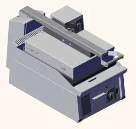
This appliance is a burger machine designed for use in industrial kitchens and recommended for use by professional users.
TECHINICAL INFORMATION
| Product Code | GGM-BRG01-E15-0001 |
| Dimensions (mm) | 400x810x500 |
| Weight (kg) | 64 |
| Gross Dimensions (mm) | 450x830x640 |
| Gross Weight (kg) | 76 |
| Electric Input (V) | 230 |
| Cable (mm²) | 5×2,5 |
| Power (KW) | 6,2 |
| Fuse (A) | 3×25 |
TRANSPORTATION AND STORAGE CONDITIONS
- The device should be placed in the box vertically.
- If the transport distance is far, it should be moved slowly, if necessary, the device should be fixed to the pallet against shaking or its balance should be maintained by a person.
- While carrying the product, do not hit or drop it.
- If the product is to be stored before the first use, the original packaging must be stored unopened.
- If it is to be stored after the device, it must be protected by cleaning and packaging.
- During pallet transport, forklift legs should be placed under the pallet while transported. You must contact the main body at a minimum of two points with the forks of the forklift. Otherwise, the pallet cannot be transported in a balanced way.


UNPACKING
- Please unpack the package according to the security codes and ordinances of the current country and get rid of the pack. Parts which contact with food are produced by stainless steel. All plastic parts are marked by the material’s symbol.
- Please check that all parts of the appliance had come completely and if they are damaged or not during the shipping.
- After the installation of the device, please throw away the packaging materials by paying attention to safety and environmental conditions. For reuse of waste packages, throw them into the relevant recycling bins according to their properties (foil, cardboard, styrofoam). When throwing away any electrical equipment, make it unusable by cutting the cable.
INSTALLATION
- Installation should be done by a qualified technician according to the instructions. Our company cannot be held responsible for any damage to people, animals or property due to incorrect installation.
- In case the device malfunctions, turn off the device. Only a service center authorized by the manufacturer should service the device. Ask for original spare parts.
- The ground on which the device will be placed must be flat and it must be ensured that the device operates on a scale. Take necessary precautions against the risk of the product tipping over.
- Connection to the electrical power supply must be made by a competent person.
- Please be sure that the voltage connected to the appliance must be equal to the voltage which is on the appliance’s label.
- The ground connection of the device must be made in accordance with standards and safety rules.
- The grounding of the device should be connected to the grounding line which is the closest panel of electrical installation.
- Device electrical connection, main fuse and leakage current fuse must be made in accordance with the current regulations and rules.
- In places with high electrical noise, an isolation transformer and line filter should be used on the supply line.
- If more than one electronic device is used, a separate supply line must be installed for each device.
- No control circuit should be connected to the supply line of the device.
- Cables that carry the sensor and input signals to the device should be carried as far as possible and separately from the supply, control, switched inductive load cables and they should be prevented from being affected.
- Necessary precautions should be taken to prevent liquid leakage and metal parts to become conductive into the device. Otherwise, accidents such as fire and electric shock may occur.
SAFETY INSTRUCTIONS
- This device must be installed in accordance with current regulations and used only in a well-ventilated area. Consult instructions for setting up the device and before use.
- The device is made for industrial use and should only be used by personnel trained in the device.
- Do not interfere with the device without using appropriate protective equipment.
- Keep the device cable away from hot surfaces.
- For the long-lasting of the device, never run it idle for a long time. When the device is not used, it must be turned off. In long-term use, the device should be turned off and
rested for at least 10 minutes every 4 hours. - All kinds of flammable solid-liquid materials (clothes, alcohol and derivatives, petrochemical products, wood and plastic materials, curtains, etc.) should never be kept in the
the area where the device is operated. - Because of any reason if there is a fire or flame flare where the appliance is used, turn off all gas valves and electric contractor switch quickly and use a fire extinguisher. Never use water to extinguish the fire.
- Damages caused by lack of grounding connection will not be covered under warranty.
- Do not use non-original spare parts on the device. In case you use for the device spare parts not supplied by our company, the device will be out of warranty.
OPERATION INFORMATION
It should payed attention to warnings as below:
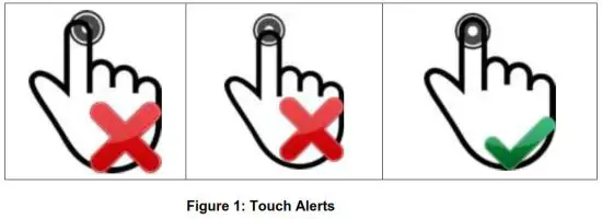
- When the device is energized, no button should be touched until the ON / OFF button lights up.
- Information about the touch-type is given in figure 1 above.


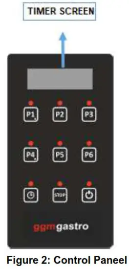
| If P1 stage is selected while the device is on, RL1 gives an output for a preset of 10 seconds. Press the Hold | |
| If P2 stage is selected while the device is on, RL1 gives an output for a preset of 20 seconds. Press Hold | |
| If P3 stage is selected while the device is on, RL1 gives an output for a preset of 30 seconds. Press Hold | |
| If P4 stage is selected while the device is on, RL1 gives an output for a preset of 40 seconds. Press Hold | |
| If P5 stage is selected while the device is on, RL1 gives an output for a preset of 50 seconds. Press Hold | |
| If P6 stage is selected while the device is on, RL1 gives an output for a preset of 60 seconds. Press Hold | |
| To Change the predetermined times, press the | |
| If the STOP button is pressed while the device is running, the relay stops giving an output. | |
| It is used for turning the device on and off. |
RL1 (10A) relay output becomes active when information comes from SW1 input while the device is on. The relay continues to give an output for the selected time value. When information comes from SW2 input or the STOP button is pressed, the relay stops giving output directly.
CLEANING AND MAINTENANCE
Cleaning and maintenance after every use;
- Make sure that the plug is not plugged in or the switch is turned off while cleaning the device.
- Clean the surface of the device after each use.
- If the device will not be used for a long time, the surfaces should be covered with a thin layer of Vaseline.
- Do not use abrasive cleaning chemicals as these can leave harmful residues.
- Do not use pressurized water and steam while cleaning the device.
- Do not clean the outer stainless surface of the device with a cleaner that can scratch the material such as wire wool.
Periodic cleaning and maintenance;
- Maintenance should be done by qualified personnel.
- Parts that need to be removed during periodic cleaning should be removed and reassembled by technical service personnel.
- According to the frequency of use, the electrical maintenance of the device should be done by spraying dry air after the electrical connection is cut.
TROUBLESHOOTING
| PROBLEM | REASON | HOW TO REMOVE |
| THE APPLIANCE DOESN’T OPERATE | – The device may not be receiving electricity. – Circuit breaker may not be open. | – Check the electrical connection. – Check the fuse box connection. |
| DEVICE STOPPED | – The device may stop due to low voltage. | – Check the voltage. |
√ If any of the security functions are not working, do not use the device and contact our authorized services.
EXPLODING DRAWING AND SPARE PART LIST
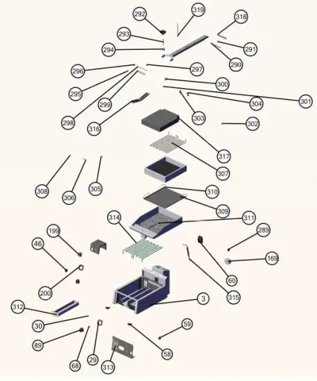
EXPLODING DRAWING AND SPARE PART LIST
| BURGER MACHINE | ||
| NO | PART NAME | P.CODE |
| 3 | BASE FRAME | – |
| 29 | BUTTON BUFFER | OMK-YP-00028 |
| 30 | RED LED | OMK-YP-00029 |
| 46 | SWITCH | OMK-YP-00045 |
| 58 | PLASTIC | OMK-YP-00057 |
| 59 | FEET | OMK-YP-00058 |
| 60 | ENERGY INPUT | OMK-YP-00059 |
| 68 | BUTTON APPARAT | OMK-YP-00067 |
| 89 | BUTTON | OMK-YP-00088 |
| 169 | MAGNET | OMK-YP-00165 |
| 199 | THERMOSTAT | OMK-YP-00195 |
| 200 | BUTTON BUFFER | OMK-YP-00196 |
| 289 | SWITCH | OMK-YP-00285 |
| 290 | HANDLE CENTER PIN | OMK-YP-00286 |
| 291 | HANDLE CENTER RING | OMK-YP-00287 |
| 292 | VOLAND | OMK-YP-00288 |
| 293 | BUTTRESS GEAR SHAFT | OMK-YP-00289 |
| 294 | BUTTRESS GEAR BEARING | OMK-YP-00290 |
| 295 | ACORN NUT | OMK-YP-00291 |
| 296 | HANDLE CONNECT | OMK-YP-00292 |
| 297 | HANDLE LIFT BUTTON | OMK-YP-00293 |
| 298 | GIGON | OMK-YP-00294 |
| 299 | HANDLE PIPE | OMK-YP-00295 |
| 300 | ELEVATION-MIDDLE | OMK-YP-00296 |
| 301 | POLIAMID FLAKE | OMK-YP-00297 |
| 302 | REINFORCEMENT PART | OMK-YP-00298 |
| 303 | SPRING | OMK-YP-00299 |
| 304 | ELEVATION-FRONT-BACK | OMK-YP-00300 |
| 305 | SCREW ELEVATION | OMK-YP-00301 |
| 306 | PIN | OMK-YP-00302 |
| 307 | RESISTANCE | OMK-YP-00303 |
| 308 | RING | OMK-YP-00304 |
| 309 | TENSION SHAFT | OMK-YP-00305 |
| 310 | TEFLON BAND | OMK-YP-00306 |
| 311 | TOP TABLE | – |
| 312 | LUBRICATOR | – |
| 313 | ELECTRONIC CARD | OMK-YP-00307 |
| 314 | RESISTANCE | OMK-YP-00308 |
| 315 | PISTON | OMK-YP-00309 |
| 316 | ELEVATION SHEET | OMK-YP-00310 |
| 317 | GLASS FIBER | – |
| 318 | HANDLE PIN PIPE | OMK-YP-00311 |
| 319 | ELEVATION BOLT | OMK-YP-00312 |
ELECTRICAL CIRCUIT DIAGRAM
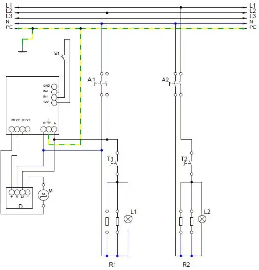
| S1 | LID SWITCH |
| T1 | BOTTOM THERMOSTAT |
| T2 | TOP THERMOSTAT |
| M | MAGNET |
| D | DIODE |
| L1 | BOTTOM THERMOSTAT SIGNAL LAMP |
| L2 | TOP THERMOSTAT SIGNAL LAMP |
| R1 | BOTTOM RESISTANCE GROUP 2X1500 W |
| R2 | TOP RESISTANCE GROUP 2X1500 W |


