
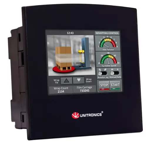
UNITRONICS SM35-J-TA22 HMI Display Unit
General Description
All of the controllers covered in this guide are micro-PLC+HMI, rugged programmable logic controllers that comprise built-in operating panels and on-board I/Os.
| Item | SM35-J-TA22 | SM43-J-TA22 | SM70-J-TA22 |
| On-board I/O | Model Dependent | ||
| Screen | 3.5″ Color Touch | 4.3″ Color Touch | 7″ Color Touch |
| Keypad or Function Keys | None | ||
| Programming Com Port, Built-in | |||
| RS232 | Yes | None | None |
| USB device, mini-B | None | Yes | Yes |
| Com Ports, separate order, user-installed | The user may install a CANbus module (V100-17-CAN), and one of the following: · RS232/RS485 port (V100-17-RS4/V100-17-RS4X) · Ethernet (V100-17-ET2) | ||
Standard Kit Contents
| Standard Kit Contents | |||
| Item | SM35-J-TA22 | SM43-J-TA22 | SM70-J-TA22 |
| Controller | Yes | ||
| Terminal Blocks | Yes | ||
| Battery | Yes (installed) | Yes (installed) | Yes |
| Mounting Brackets | Yes (2 parts) | Yes (4 parts) | Yes (6 parts) |
| Rubber Seal | Yes | ||
Alert Symbols and General Restrictions
When any of the following symbols appear, read the associated information carefully.
| Symbol | Meaning | Description | |
| Danger | The identified danger causes physical and property damage. | ||
| Warning | The identified danger could cause physical and property damage. | ||
| Caution | Caution | Use caution. | |
- Before using this product, the user must read and understand this document.
- All examples and diagrams are intended to aid understanding, and do not guarantee operation. Unitronics accepts no responsibility for actual use of this product based on these examples.
- Please dispose of this product according to local and national standards and regulations.
- Only qualified service personnel should open this device or carry out repairs.
Failure to comply with appropriate safety guidelines can cause severe injury or property damage.
- Do not attempt to use this device with parameters that exceed permissible levels.
- To avoid damaging the system, do not connect/disconnect the device when power is on.
Environmental Considerations
- Do not install in areas with: excessive or conductive dust, corrosive or flammable gas, moisture or rain, excessive heat, regular impact shocks or excessive vibration, in accordance with the standards given in the product’s technical specification sheet.
- Do not place in water or let water leak onto the unit.
- Do not allow debris to fall inside the unit during installation.
- Ventilation: 10mm space required between controller’s top/bottom edges & enclosure walls.
- Install at maximum distance from high-voltage cables and power equipment.
UL Compliance
The following section is relevant to Unitronics’ products that are listed with the UL.
The following models: V130-33-R34, V130-J-R34, V130-T4-ZK1, V350-35-RA22, V350-J-RA22, V350-35-R34, V350-J-R34, V430-J-R34, SM35-J-T20, SM43-J-T20 are UL listed for Hazardous Locations.
The following models: V130-33-B1, V130-J-B1, V130-33-TA24, V130-J-TA24, V130-33-T38,V130-J-T38 V130-33-TR20, V130-J-TR20, V130-33-TR34, V130-J-TR34, V130-33-RA22, V130-J-RA22, V130-33-TRA22, V130-J-TRA22, V130-33-T2, V130-J-T2, V130-33-TR6, V130-J-TR6, V130-33-R34, V350-35-B1, V130-T4-ZK1, V350-J-B1, V350-35-TA24, V350-J-TA24, V350-35-T38, V350-J-T38, V350-35-TR20, V350-J-TR20, V350-35-TR34, V350-J-TR34, V350-35-TRA22, V350-J-TRA22, V350-35-T2, V350-J-T2, V350-35-TR6, V350-J-TR6, V350-S-TA24, V350-JS-TA24, V350-35-RA22, V350-J-RA22, V350-35-R34, V430-J-B1, V430-J-TA24, V430-J-T38, V430-J-R34, V430-J-RH2, V430-J-TR34, V430-J-RA22, V430-J-TRA22, V430-J-T2, V430-J-RH6, SM35-J-D4, SM35-J-R20 SM35-J-RA22, SM35-J-TA22, SM43-J-R20, SM43-J-RA22, SM43-J-TA22, SM35-J-T20, SM43-J-T20 SM70-J-R20, SM70-J-RA22, SM70-J-T20, SM70-J-T38, SM70-J-TA22, SM70-J-TRA22 are UL listed for Ordinary Location.
For models from series V130, V130-J, V430, that include “T4” or “J4” in the Model name, Suitable for mounting on the flat surface of Type 4X enclosure.
For examples: V130-T4-R34, V130-J4-R34, V430-J4-T2, SM43-J4-R20.
UL Ordinary Location
In order to meet the UL ordinary location standard, panel-mount this device on the flat surface of Type 1 or 4 X enclosures
UL Ratings, Programmable Controllers for Use in Hazardous Locations, Class I, Division 2, Groups A, B, C and D
These Release Notes relate to all Unitronics products that bear the UL symbols used to mark products that have been approved for use in hazardous locations, Class I, Division 2, Groups A, B, C and D.
Caution This equipment is suitable for use in Class I, Division 2, Groups A, B, C and D, or Non-hazardous locations only.
- Input and output wiring must be in accordance with Class I, Division 2 wiring methods and in accordance with the authority having jurisdiction.
- WARNING—Explosion Hazard—substitution of components may impair suitability for Class I, Division 2.
- WARNING – EXPLOSION HAZARD – Do not connect or disconnect equipment unless power has been switched off or the area is known to be non-hazardous.
- WARNING – Exposure to some chemicals may degrade the sealing properties of material used in Relays.
- This equipment must be installed using wiring methods as required for Class I, Division 2 as per the NEC and/or CEC.
Panel-Mounting
For programmable controllers that can be mounted also on panel, in order to meet the UL Haz Loc standard, panel-mount this device on the flat surface of Type 1 or Type 4X enclosures.
Relay Output Resistance Ratings
The products listed below contain relay outputs:
Programmable controllers, Models: V430-J-R34, V130-33-R34, V130-J-R34 and V350-35-R34, V350-J-R34
- When these specific products are used in hazardous locations, they are rated at 3A res.
- Except for models V430-J-R34, V130-33-R34, V130-J-R34, V130-T4-ZK1 and V350-35-R34, V350-J-R34, when these specific products are used in non-hazardous environmental conditions, they are rated at 5A res, as given in the product’s specifications.
Communication and Removable Memory Storage
When products comprise either USB communication port, SD card slot, or both, neither the SD card slot nor the USB port are intended to be permanently connected, while the USB port is intended for programming only.
Removing / Replacing the battery
When a product has been installed with a battery, do not remove or replace the battery unless the power has been switched off, or the area is known to be non-hazardous.
Please note that it is recommended to back up all data retained in RAM, in order to avoid losing data when changing the battery while the power is switched off. Date and time information will also need to be reset after the procedure.
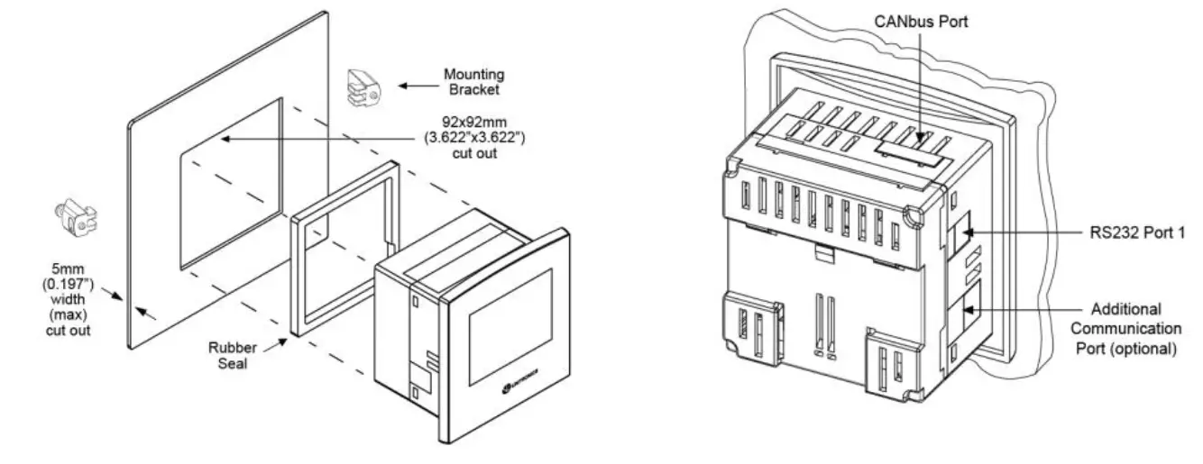
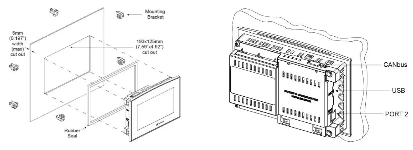
Mounting
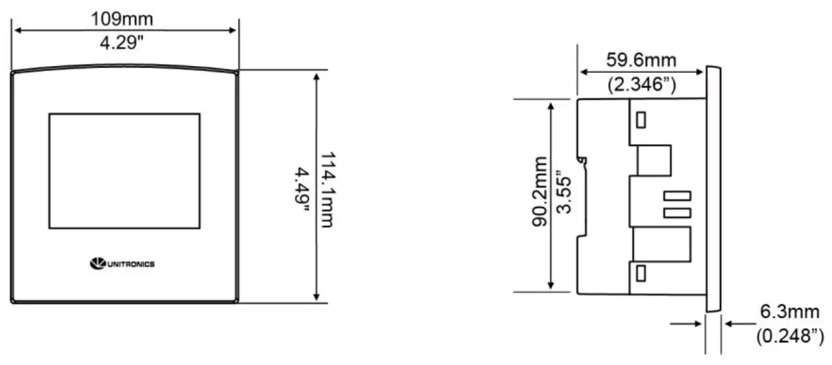
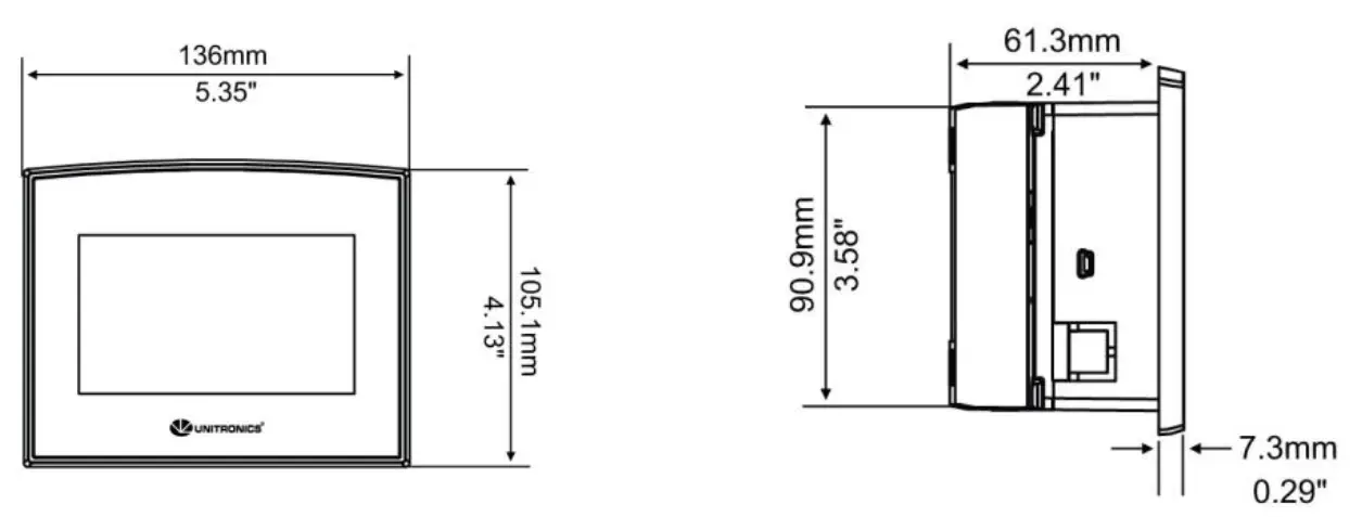
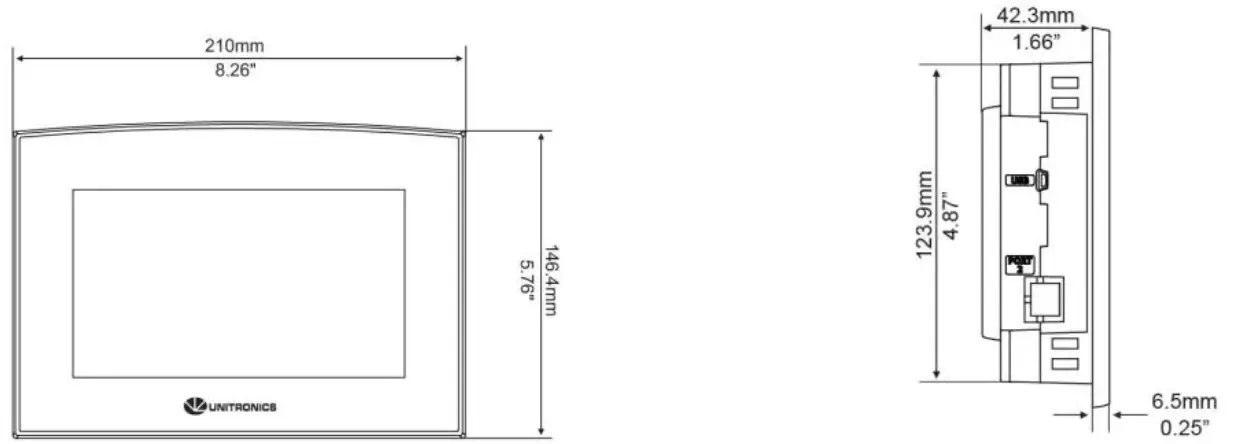
Dimensions
SM35
SM43
SM70
Panel Mounting
Before you begin, note that the mounting panel cannot be more than 5 mm thick.
UL listed models:
To meet the UL508 standard, panel-mount the device on the flat surface of a Type 1 enclosure.
- Make a panel cut-out of the appropriate size:
▪ SM35: 92x92mm (3.622”x3.622”).
▪ SM43: 122.5×91.5mm (4.82”x3.6”).
▪ SM70: 193x125mm (7.59”x4.92”). - Slide the controller into the cut-out, ensuring that the rubber seal is in place.
- Push the mounting brackets into their slots on the sides of the panel as shown in the figure below.
- Tighten the bracket’s screws against the panel. Hold the bracket securely against the unit while tightening the screw. The torque required is 0.35 N·m (3.1 in-lb).
- When properly mounted, the controller is squarely situated in the panel cut-out as shown in the accompanying figures.
SM35
SM43
SM70
Caution
▪ Do not apply torque exceeding 0.35 N·m (3.1 in-lb) of torque to tighten the
▪ bracket screws. Using excessive force to tighten the screw can damage this product.
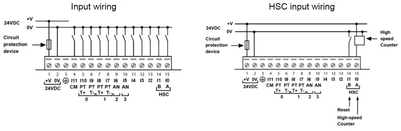
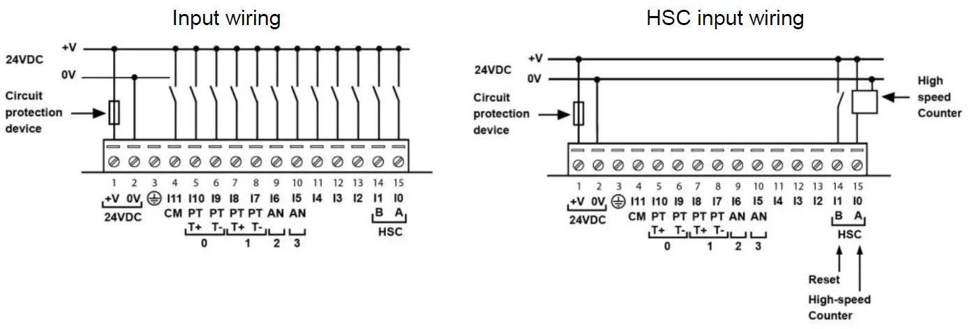
Wiring
- Do not touch live wires.
- Install an external circuit breaker. Guard against short-circuiting in external wiring.
- Use appropriate circuit protection devices.
- Unused pins should not be connected. Ignoring this directive may damage the device.
- Double-check all wiring before turning on the power supply.
- To avoid damaging the wire, do not exceed a maximum torque of 0.5 N·m (5 kgf·cm).
- Do not use tin, solder, or any substance on stripped wire that might cause the wire strand to break.
Caution Install at maximum distance from high-voltage cables and power equipment.
Wiring Procedure
Use crimp terminals for wiring; use 3.31 mm² –0.13 mm² wire (12-26 AWG):
- Strip the wire to a length of 7±0.5mm (0.270–0.300“).
- Unscrew the terminal to its widest position before inserting a wire.
- Insert the wire completely into the terminal to ensure a proper connection.
- Tighten enough to keep the wire from pulling free.
- Input or output cables should not be run through the same multi-core cable or share the same wire.
- Allow for voltage drop and noise interference with I/O lines used over an extended distance.
Use wire that is properly sized for the load. - The controller and I/O signals must be connected to the same 0V signal.
I/Os
SM35/43/70-J-TA22 models comprise a total 12 inputs, 8 digital outputs and 2 analog outputs.
Input functionality can be adapted as follows:
All 12 inputs may be used as digital inputs. They may be wired in a group via a single jumper as either npn or pnp.
In addition, according to jumper settings and appropriate wiring:
- Inputs 5 and 6 can function as either digital or analog inputs.
- Input 0 can function as a high-speed counter, as part of a shaft-encoder, or as a normal digital input.
- Input 1 can function as either a counter reset, normal digital input, or as part of a shaft-encoder.
- If input 0 is set as a high-speed counter (without reset), input 1 can function as a normal digital input.
- Inputs 7-8 and 9-10 can function as digital, thermocouple, or PT100 inputs; Input 11 can also serve as the CM signal for PT100.
Input Jumper Settings
The tables below show how to set a specific jumper to change input functionality. To access the I/O jumpers, you must open the controller according to the instructions on page 11.
Incompatible jumper settings and wiring connections may seriously damage the controller.
| Digital Inputs 0-11: Set Type | |||
| Set to | JP12 (all Inputs) | ||
| npn (sink) | A | ||
| pnp (source)* | B | ||
| Inputs 7/8: Set Type – Digital or RTD/TC #1 | |||
| Set to | JP1 | JP2 | JP3 |
| Digital* | A | A | A |
| Thermocouple | B | B | B |
| PT100 | B | A | B |
| Inputs 9/10: Set Type – Digital or RTD/TC #0 | |||
| Set to | JP5 | JP6 | JP7 |
| Digital* | A | A | A |
| Thermocouple | B | B | B |
| PT100 | B | A | B |
| Input 11: Set Type – Digital or CM for PT100 | |||
| Set to | JP11 | ||
| Digital* | A | ||
| CM for PT100 | B | ||
| Input 5: Set Type – Digital or Analog #3 | |||
| Set to | JP4 | JP10 | |
| Digital* | A | A | |
| Voltage | B | A | |
| Current | B | B | |
| Input 6: Set Type – Digital or Analog #2 | |||
| Set to | JP8 | JP9 | |
| Digital* | A | A | |
| Voltage | B | A | |
| Current | B | B | |
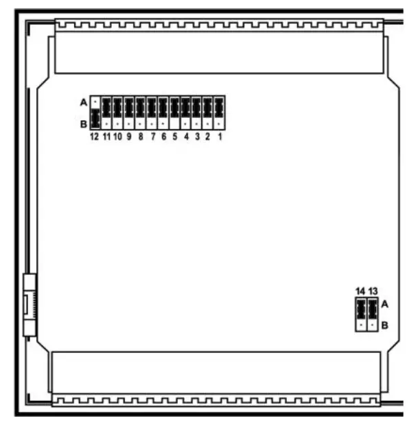
*Default settings
| Analog Output 0: Set to Voltage/Current | ||
| Set to | JP13 | |
| Voltage* | A | |
| Current | B | |
| Analog Output 1: Set to Voltage/Current | ||
| Set to | JP14 | |
| Voltage* | A | |
| Current | B | |
npn (sink) Input
pnp (source) Input
Shaft-encoder
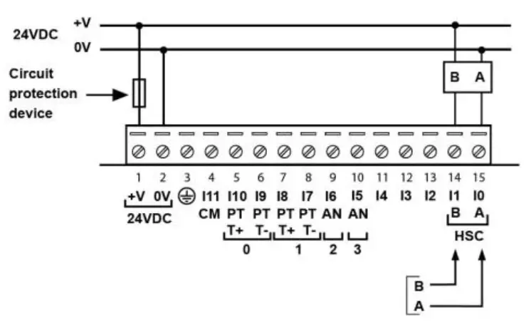
Analog Input
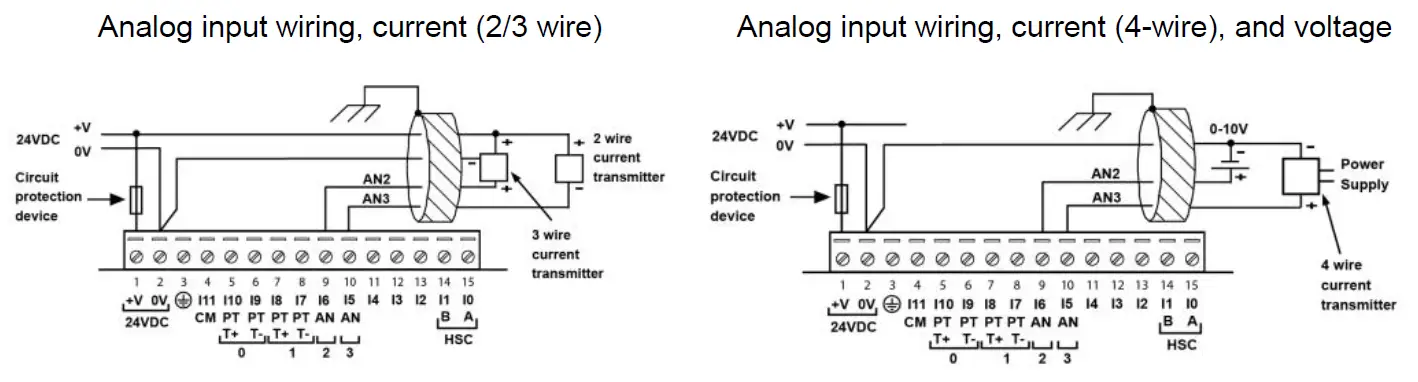
▪ Shields should be connected at the signal’s source.
▪ The 0V signal of the analog input must be connected to the controller’s 0V.
Thermocouple
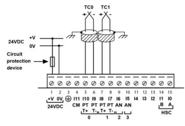
- Thermocouple 0: use Input 9 as negative input and 10 as positive.
- Thermocouple 1: use Input 7 as negative input and 8 as positive.
| Type | Temp. Range | Wire Color | |
| ANSI (USA) | BS1843 (UK) | ||
| mV | -5 to 56mV | ||
| B | 200 to 1820˚C (300 to 3276˚F) | +Grey -Red | +None -Blue |
| E | -200 to 750˚C (-328 to 1382˚F) | +Violet -Red | +Brown -Blue |
| J | -200 to 760˚C (-328 to 1400˚F) | +White -Red | +Yellow -Blue |
| K | -200 to 1250˚C (-328 to 2282˚F) | +Yellow -Red | +Brown -Blue |
| N | -200 to 1300˚C (-328 to 2372˚F) | +Orange -Red | +Orange -Blue |
| R | 0 to 1768˚C (32 to 3214˚F) | +Black -Red | +White -Blue |
| S | 0 to 1768˚C (32 to 3214˚F) | +Black -Red | +White -Blue |
| T | -200 to 400˚C (-328 to 752˚F) | +Blue -Red | +White -Blue |
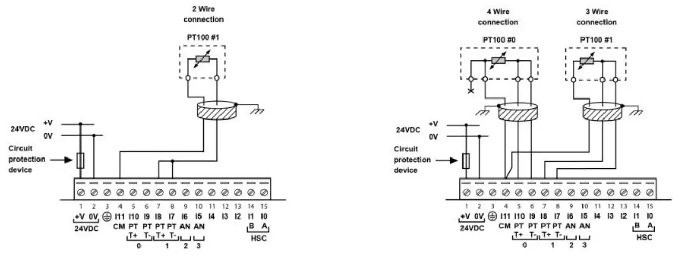
RTD
▪ PT100 (Sensor 0): use Input 9 and 10, related to CM signal.
▪ PT100 (Sensor 1): use Input 7 and 8, related to CM signal.
▪ 4 wire PT100 can be used by leaving one of the sensor leads unconnected.
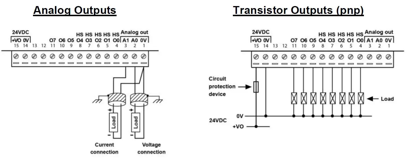
▪ The 0V signals of the transistor and the analog outputs must be connected to the controller’s 0V.
▪ Outputs 0 to 4 can be used as PWM outputs.
Power Supply
The controller requires an external 24VDC power supply.
- The power supply must include double insulation. Outputs must be rated as SELV/PELV/Class2/Limited Power.
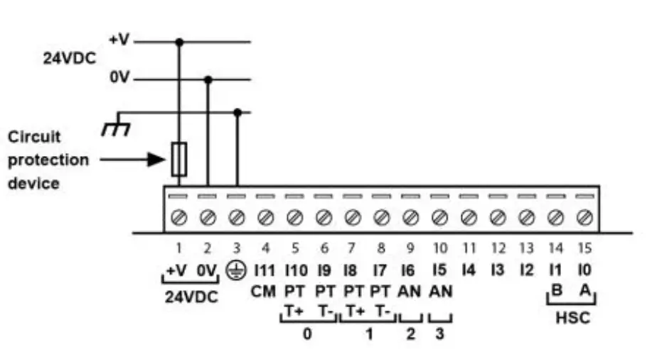
- Use separate wires to connect the functional earth line (pin 3) and the 0V line (pin 2) to the system earth ground.
- Install an external circuit breaker. Guard against short-circuiting in external wiring.
- Double-check all wiring before turning on the power supply.
- Do not connect either the ‘Neutral’ or ‘Line’ signal of the 110/220VAC to device’s 0V pin
- In the event of voltage fluctuations or non-conformity to voltage power supply specifications, connect the device to a regulated power supply.
Earthing the PLC+HMI
To maximize system performance, avoid electromagnetic interference by:
- Mounting the controller on a metal panel.
- Connect each common and ground connection directly to the earth ground of your system.
- For ground wiring uses the shortest and thickest possible wire.
Communication Port
▪ Turn off power before making communications connections.
▪ Always use the appropriate port adapters.
SM43/SM70-J-TA22
This series comprises a USB port.
Caution The USB port in SM43 Series is not isolated. Make sure that the PC and the controller are grounded to same potential.
The USB port may be used for programming, OS download and PC access.
Pinouts
The pinouts below show the PLC port signals.
| RS232 | |
| Pin # | Description |
| 1 | Not connected |
| 2 | 0V reference |
| 3 | TXD signal |
| 4 | RXD signal |
| 5 | 0V reference |
| 6 | Not connected |
Opening the Controller
- Before performing these actions, touch a grounded object to discharge any electrostatic charge.
- Avoid touching the PCB board directly. Hold the PCB board by its connectors.
- Turn off the power supply, disconnects, and dismounts the controller.
- The back cover of the controller comprises 4 screws, located in the corners. Remove the screws, and pull off the back cover.
Changing I/O Settings
The I/O board of the controller is now exposed, enabling you to change
I/O settings (module dependent) according to the jumpers setting above.
Note: Photo is for illustration purposes only. (Using SM70)

Closing the Controller
Replace the back cover of the controller and fasten the corner screws.
Note that you must replace the back cover securely before powering up the controller.
| Power Supply | ||||
| Item | SM35-J-TA22 | SM43-J-TA22 | SM70-J-TA22 | |
| Input voltage | 24VDC | |||
| Permissible range | 20.4VDC to 28.8VDC with less than 10% ripple | |||
| Max. current consumption | See Note 1 | |||
| npn inputs | 225mA@24VDC | 225mA@24VDC | 350mA@24VDC | |
| pnp inputs | 185mA@24VDC | 185mA@24VDC | 310mA@24VDC | |
| Notes: | ||||
| 1. To calculate the actual power consumption, subtract the current for each unused element from the maximum current consumption value according to the values below: | ||||
| Backlight | Ethernet card | All Analog Outputs, voltage/current | ||
| SM35/SM43 | 20mA | 35mA | 48mA/30mA* | |
| SM70 | 80mA | 35mA | 48mA/30mA* | |
| *If the analog outputs are not configured, then subtract the higher value. | ||||
| Digital Inputs | |
| Number of inputs | 12. See Note 2 |
| Input type | See Note 2 |
| Galvanic isolation | None |
| Nominal input voltage | 24VDC |
| Input voltage | |
| pnp (source) | 0-5VDC for Logic ‘0’ 17-28.8VDC for Logic ‘1’ |
| npn (sink) | 17-28.8VDC for Logic ‘0’ 0-5VDC for Logic ‘1’ |
| Input current | 3.7mA@24VDC |
| Input impedance | 6.5KΩ |
| Response time | 10ms typical, when used as normal digital inputs |
| Input cable length | |
| Normal digital input | Up to 100 meters |
| High Speed Input | Up to 50 meters, shielded, see Frequency table below |
Notes:
- This model comprises a total of 12 inputs.
All 12 inputs may be used as digital inputs. They may be wired in a group via a single jumper as either npn or pnp.
In addition, according to jumper settings and appropriate wiring:- Inputs 5 and 6 can function as either digital or analog inputs.
- Input 0 can function as a high-speed counter, as part of a shaft-encoder, or as normal digital inputs.
- Input 1 can function as either counter reset, normal digital input, or as part of a shaft-encoder.
- If input 0 is set as a high-speed counter (without reset), input 1 can function as a normal digital input.
- Inputs 7-8 and 9-10 can function as digital, thermocouple, or PT100 inputs; input 11 can also serve as the CM signal for PT100.
- pnp/npn maximum frequency is at 24VDC.
Notes:
- Conversion times are accumulative and depend on the total number of analog inputs configured.
For example, if only one analog input (fast mode) is configured, the conversion time will be 30ms; however, if two analog (normal mode) and two RTD inputs are configured, the conversion time will be 100ms + 100ms + 300ms + 300ms = 800ms. - The analog value can indicate faults as shown below:
| Value: 12-bit | Value: 14-bit | Possible Cause |
| -1 | -1 | Deviates slightly below the input range |
| 4096 | 16384 | Deviates slightly above the input range |
| 32767 | 32767 | Deviates greatly above or below the input range |
| RTD Inputs | ||
| RTD Type | PT100 | |
| Temperature coefficient a | 0.00385/0.00392 | |
| Input range | -200 to 600°C/-328 to 1100°F. 1 to 320Ω. | |
| Isolation | None | |
| Conversion method | Voltage to frequency | |
| Resolution | 0.1°C/0.1°F | |
| Conversion time | 300ms minimum per channel. See Note 4 above | |
| Input impedance | >10MΩ | |
| Auxillary current for PT100 | 150μA typical | |
| Full-scale error | ±0.4% | |
| Linearity error | ±0.04% | |
| Status indication | Yes. See Note 6 | |
| Cable length | Up to 50 meters, shielded | |
| Notes: | ||
| 6. The analog value can indicate faults as shown below: | ||
| Value | Possible Cause | |
| 32767 | Sensor is not connected to input, or value exceeds permissible range | |
| -32767 | Sensor is short-circuited | |
| Thermocouple Inputs | ||
| Input range | See Note 7 | |
| Isolation | None | |
| Conversion method | Voltage to frequency | |
| Resolution | 0.1°C/ 0.1°F maximum | |
| Conversion time | 100ms minimum per channel. See Note 7 above | |
| Input impedance | >10MΩ | |
| Cold junction compensation | Local, automatic | |
| Cold junction compensation error | ±1.5°C/±2.7°F maximum | |
| Absolute maximum rating | ±0.6VDC | |
| Full-scale error | ±0.4% | |
| Linearity error | ±0.04% | |
| Warm-up time | ½ hour typically, ±1°C/±1.8°F repeatability | |
| Status indication | Yes. See Note 6 above | |
Notes: The device can also measure voltage within the range of -5 to 56mV, at a resolution of 0.01mV.
The device can also measure raw value frequency at a resolution of 14-bits (16384). Input ranges are shown in the following table:
| Type | Temp. Range |
| mV | -5 to 56mV |
| B | 200 to 1820˚C (300 to 3276˚F) |
| E | -200 to 750˚C (-328 to 1382˚F) |
| J | -200 to 760˚C (-328 to 1400˚F) |
| K | -200 to 1250˚C (-328 to 2282˚F) |
| Type | Temp. Range |
| N | -200 to 1300˚C (-328 to 2372˚F) |
| R | 0 to 1768˚C (32 to 3214˚F) |
| S | 0 to 1768˚C (32 to 3214˚F) |
| T | -200 to 400˚C (-328 to 752˚F) |
Digital Outputs
| Digital Outputs | |
| Number of outputs | 8 transistor pnp (source) |
| Output type | P-MOSFET (open drain) |
| Isolation | None |
| Output current (resistive load) | 0.5A maximum per output 3A maximum total per common |
| Maximum frequency | 50Hz (resistive load) 0.5Hz (inductive load) |
| PWM maximum frequency | 0.5KHz (resistive load). See Note 8 |
| Short circuit protection | Yes |
| Short circuit indication | Via software |
| On voltage drop | 0.5VDC maximum |
| Power supply for outputs | |
| Operating voltage | 20.4 to 28.8VDC |
| Nominal voltage | 24VDC |
| Notes: | |
| 8. Outputs 0 to 4 can be used as PWM outputs. | |
Notes: Outputs 0 to 4 can be used as PWM outputs.
Analog Outputs
| Analog Outputs | |
| Number of outputs | 2 |
| Output range | 0-10V, 4-20mA. See Note 9 |
| Resolution | 12-bit (4096 units) |
| Conversion time | Both outputs are updated per scan |
| Load impedance | 1kΩ minimum—voltage 500Ω maximum—current |
| Galvanic isolation | None |
| Linearity error | ±0.1% |
| Operational error limits | ±0.2% |
Notes: Note that the range of each I/O is defined by wiring, jumper settings, and within the controller’s software.
Graphic Display Screen
| Item | SM35-J-TA22 | SM43-J-TA22 | SM70-J-TA22 |
| LCD Type | TFT, LCD display | TFT, LCD display | TFT, LCD display |
| Illumination backlight | White LED | White LED | White LED |
| Display resolution | 320×240 pixels | 480×272 pixels | 800×480 pixels |
| Viewing area | 3.5″ | 4.3″ | 7″ |
| Colors | 65,536 (16-bit) | 65,536 (16-bit) | 65,536 (16-bit) |
| Touchscreen | Resistive, analog | Resistive, analog | Resistive, analog |
| Screen brightness control | Via software (Store value to SI 9, values range: 0 to 100%) | ||
| Virtual Keypad | Displays virtual keyboard when the application requires data entry. | ||
Program
| Program | ||||
| Item | SM35-J-TA22 | SM43-J-TA22 | SM70-J-TA22 | |
| Memory size | ||||
| Application Logic | 80K | 192K | 192K | |
| Images | 1.5M | 3M | 8M | |
| Fonts | 320K | 320K | 512K | |
| Operand type | Quantity | Symbol | Value | |
| Memory Bits | 512 | MB | Bit (coil) | |
| Memory Integers | 256 | MI | 16-bit signed/unsigned | |
| Long Integers | 32 | ML | 32-bit signed/unsigned | |
| Double Word | 32 | DW | 32-bit unsigned | |
| Memory Floats | 24 | MF | 32-bit signed/unsigned | |
| Fast Bits | 64 | XB | Fast Bits (coil) – not retained | |
| Fast Integers | 32 | XI | 16 bit signed/unsigned (fast, not retained) | |
| Fast Long Integers | 16 | XL | 32 bit signed/unsigned (fast, not retained) | |
| Fast Double Word | 16 | XDW | 32 bit unsigned (fast, not retained) | |
| Timers | 32 | T | Res. 10 ms; max 99h, 59 min, 59.99s | |
| Counters | 16 | C | 32-bit | |
| Data Tables | 32K dynamic data (recipe parameters, datalogs, etc.) 16K fixed data (read-only data, ingredient names, etc) | |||
| HMI displays | Up to 24 | |||
| Program scan time | 15µs per 1kb of typical application | |||
Communication Ports
| Communication Ports | |
| Port 1 | 1 channel, RS232 (SM35) , USB device (SM43/SM70) |
| Galvanic isolation | SM35 and SM43 – No SM70 – Yes |
| Baud rate | 300 to 115200 bps |
| RS232 (SM35 only) | |
| Input voltage | ±20VDC absolute maximum |
| Cable length | 15m maximum (50’) |
| USB device (SM43,SM70 only) | |
| Port type | Mini-B |
| Specification | USB 2.0 complaint; full speed |
| Cable | USB 2.0 complaint; up to 3m |
| Port 2 (optional) | See Note 10 |
| CANbus (optional) | See Note 10 |
| Notes: | |
| 10. The user may order and install one or both of the following modules: – A serial RS232/RS485 isolated/non-isolated interface module, or an Ethernet Interface module in port 2. – A CANbus module modules documentation is available on the Unitronics website. | |
Notes: The user may order and install one or both of the following modules:
- A serial RS232/RS485 isolated/non-isolated interface module, or an Ethernet Interface module in port 2.
- A CANbus module modules documentation is available on the Unitronics website.
Miscellaneous
| Miscellaneous | |
| Clock (RTC) | Real-time clock functions (date and time) |
| Battery back-up | 7 years typical at 25°C, battery back-up for RTC and system data, including variable data |
| Battery replacement | Yes. Coin-type 3V, lithium battery, CR2450 |
Dimensions
| Dimensions | |||
| Item | SM35-J-TA22 | SM43-J-TA22 | SM70-J-TA22 |
| Size | 109 x 114.1 x 68mm (4.29 x 4.49 x 2.67”). See Note 11 | 136 x 105.1 x 61.3mm (5.35 x 4.13 x 2.41”). See Note 11 | 210 x 146.4 x 42.3mm (8.26 x 5.76 x 1.66”). See Note 11 |
| Weight | 207g (7.3 oz) | 346g (12.2 oz) | 635g (22.4 oz) |
Mounting method
| Mounting method | |||
| Item | SM35-J-TA22 | SM43-J-TA22 | SM70-J-TA22 |
| Panel mounted | IP65/66/NEMA4X | IP65/66/NEMA4X | IP65/66/NEMA4X |
| DIN-rail mounted | IP20/NEMA1 | – | – |
Environment
| Environment | |
| Operational temperature | 0 to 50ºC (32 to 122ºF) |
| Storage temperature | -20 to 60ºC (-4 to 140ºF) |
| Relative Humidity (RH) | 10% to 95% (non-condensing) |
| Operating Altitude | 2000m (6562 ft) |
| Shock | IEC 60068-2-27, 15G, 11ms duration |
| Vibration | IEC 60068-2-6, 5Hz to 8.4Hz, 3.5mm constant amplitude, 8.4Hz to 150Hz, 1G acceleration. |
The information in this document reflects products at the date of printing. Unitronics reserves the right, subject to all applicable laws, at any time, at its sole discretion, and without notice, to discontinue or change the features, designs, materials and other specifications of its products, and to either permanently or temporarily withdraw any of the forgoing from the market.
All information in this document is provided “as is” without warranty of any kind, either expressed or implied, including but not limited to any implied warranties of merchantability, fitness for a particular purpose, or non-infringement. Unitronics assumes no responsibility for errors or omissions in the information presented in this document. In no event shall Unitronics be liable for any special, incidental, indirect or consequential damages of any kind, or any damages whatsoever arising out of or in connection with the use or performance of this information.
The tradenames, trademarks, logos and service marks presented in this document, including their design, are the property of Unitronics (1989) (R”G) Ltd. or other third parties and you are not permitted to use them without the prior written consent of Unitronics or such third party as may own them


