SOLUZIONE SOLARE RGA801F Sunmeter Pro Counter
GENERAL DESCRIPTION
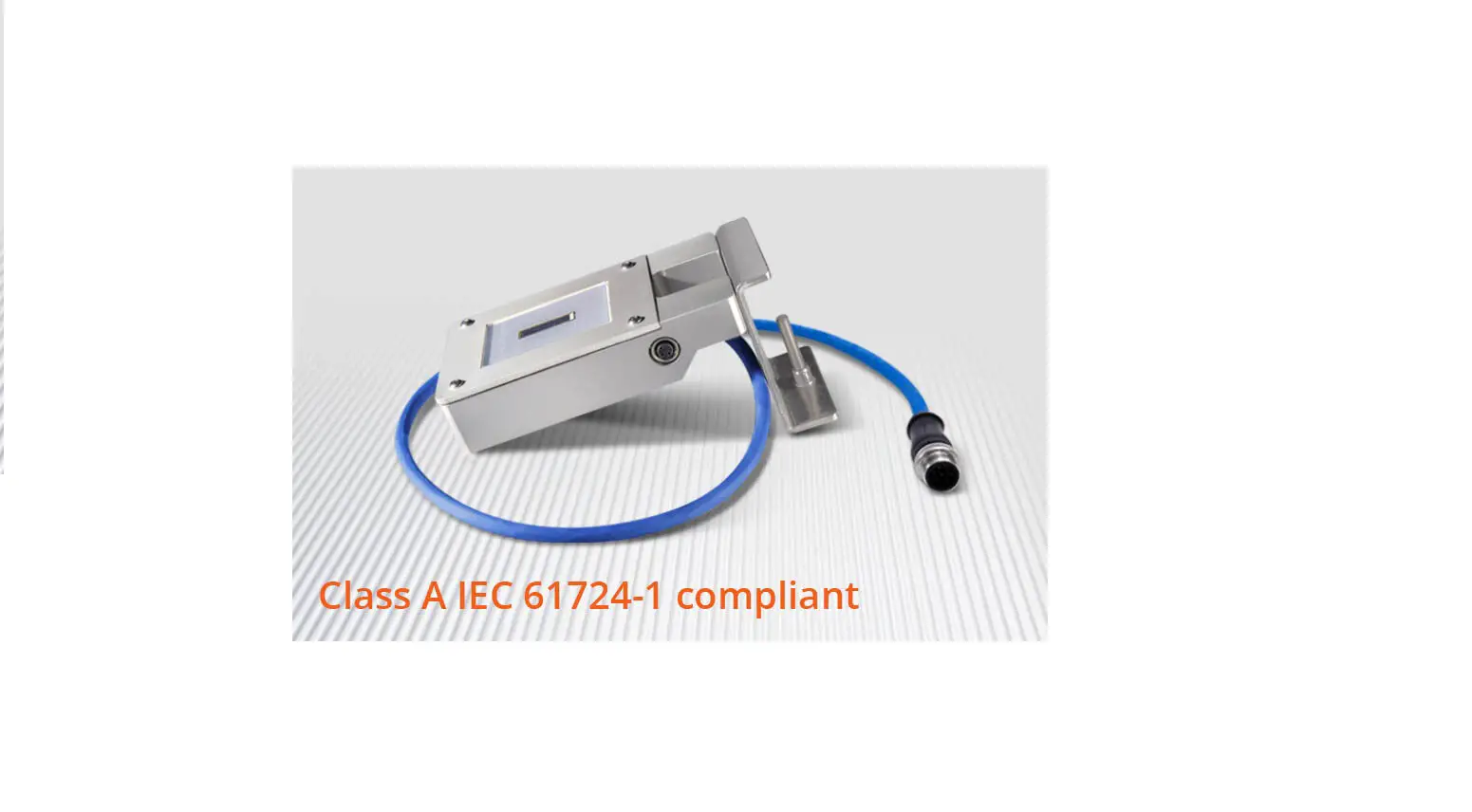
The SunMeterâ PRO (SM PRO) is a high technology electronic device primarily designed to accurately measure the solar radiation and make it available to the user in the best suitable way for its applications.
It’s mainly intended, but not limited, to be used in solar energy conversion applications (both thermal and photovoltaic) for preliminary studies, for commissioning testing and for continuous performance checking and monitoring.
It’s based on a sensing silicon element that through our proprietary TZOSâ (True Zero Ohm Shunt) technology is sampled and managed by a high-performance DSP (Digital Signal Processor) in order to enhance the signal precision and stability, achieving results that are comparable to best class radiometers.
Its monocrystalline silicon cell is laminated with small micro prismatic glass for photovoltaic modules and E.V.A., this improves its durability and stability of measurements over time.
It’s equipped with an additional input for an external PT100 RTD element in order to sense the temperature of nearby items, i.e. photovoltaic modules, ambient, etc.
The measures can be read by two outputs: a “universal” multistandard analog output for all old-fashion viewing devices and dataloggers and a powerful, versatile EIA/TIA-RS485 bus interface with the well-known industry-standard protocol Modbus RTU.
FEATURES
Inputs:
irradiance range: 0 1500 W/m2 temperature compensated
temperature range: -30 +90 °C measurable with external PT100 RTD
digital: PNP-like connection
Outputs:
analog: configurable as voltage (0 10 V / 0 5 V) or current (0 20 mA / 4 20 mA)
serial: RS485, standard Modbus RTU protocol
Measurements precision:
irradiance: < 2%
temperature: < 0.5 °C
Supply: 9 30 Vdc, protected against reverse polarity
Encapsulation: small micro prismatic glass for photovoltaic modules and E.V.A
Case: anodized aluminum with stainless steel screw-clamp to fix it on modules or montage profile
Wiring: 50 cm cable, UV resistant
Connectors: male M12 8 pin circular, IP67 code, UV resistant, matching female supplied female M8 3 pin circular IP67
Dimensions: 114 x 70 x 22 mm, with mounting bracket 128 x 70 x 65 mm (overall) Operating temperature: -20°C ÷ +80 °C (transport and storage -35°C ÷ +95 °C)Every SM is factory calibrated.
PART LIST
- SM PRO with aluminum bracket
- female M12 8 pin circular connector
- 1 long stainless steel screw (temporary positioning)
- 2 short stainless steel screws (permanent positioning)
- instruction manual
Important: the case presents a hole with a diameter of a few mm, this hole is terminated by a transpiring membrane whose purpose is the barometric compensation to avoid condensation.
DON’T PERFORATE. WARRANTY VOID IF REMOVED OR PERFORATED.
ASSEMBLY
SM PRO is provided with a bracket to apply it to structures or directly to a PV module as shown in Fig. 1 and 2: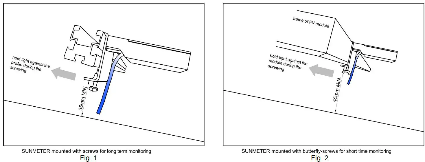
We suggest mounting SM PRO on the bottom side of a PV module because, if applied on the top side, it may be chosen by a bird as a springboard! The same considerations apply when fastening to a structure’s profile. Stainless screws are provided for permanent mounting of SM PRO on your PV plant.
CONNECTIONS
The IP67 8-pin circular male connector carries all the signals to and from the SM PRO as in Tab. 1 and Fig. 3, which shows a back view of the female connector (the fourth column indicates the colours of cables in the free pin version): 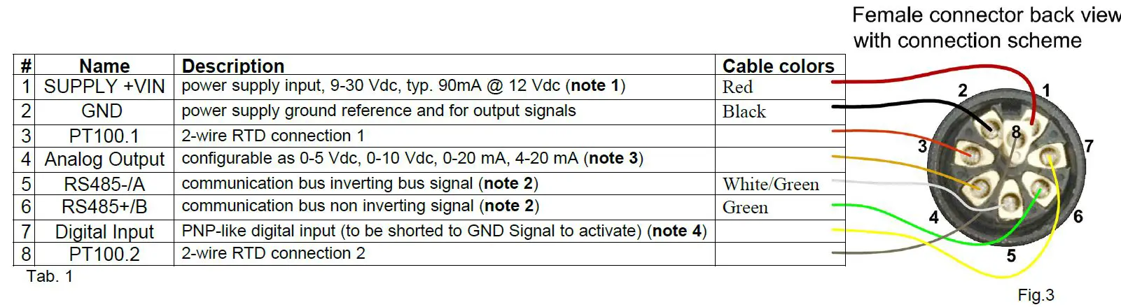
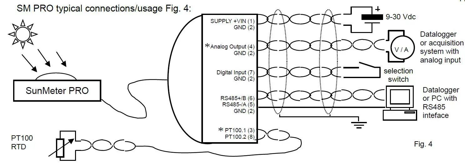
Only for the complete model (Digital and Analog Output) We strongly suggest using a shielded connection cable with twisted pairs, AWG22 / 0.32mm2
Notes:
- if analog output is used, please pay attention to choosing a power supply greater than the compliance voltage, see also note 3.
- balanced differential bus RS485 needs to be terminated, at the extremities of the bus, by a 100-120 Ω resistor (1/4 W) between RS485+/RS485- lines in order to avoid signal’s reflections. In the case that SM is the device at one extremity, place the resistor into the supplied female connector.
Even if RS485 has a –7/+12Vdc common-mode rejection range, normally sufficient to compensate for the ground potential difference between connected devices, it is strongly recommended to always carry a ground reference among the bus’s signals and to connect it to the SM PRO’s Signal GND. - please check l oad restrictions :
- in voltage modes (0÷5 / 0÷10 V) minimum load impedance is 250 / 500 Ω, we recommend a load impedance > 5 kΩ
- in current modes (0÷20 / 4÷20 mA) maximum load impedance is 1.2 kΩ, we recommend a load impedance in the 200-500 Ω range
- the compliance voltage (maximum output voltage) at full 20 mA output current and beyond, is about 2.5V l ess than power supply voltage so choose it accordingly in order to leave sufficient margin.
- the digital input need to be activated by shorting to GROUND (either supply or signal, latter preferably). Do no t attempt to supply voltage to this input.
MODBUS PROTOCOL
Modbus is a Master-Slave protocol that is widely used as an industry standard. It is simple, efficient and reliable. It can be easily used to access and collect data or exchange information between digital systems over a serial line local bus (and with its TCP/IP extension through a LAN or World Wide Web).
Please refer to specific detailed documentation and implementations freely available at www.modbus.org
SM PRO is a Modbus RTU slave that implements the following standard access functions:
| Function code | Description |
| 0x03 | READ HOLDING REGISTERS |
| 0x04 | READ INPUT REGISTERS |
| 0x06 | WRITE SINGLE REGISTER |
| 0x10 | WRITE MULTIPLE REGISTERS |
Please note that in the current implementation of SM PRO function codes 0x03 and 0x04 are equivalent and address the same data area.
Data is accessible through Modbus’s functions by 16 bits units called “registers”. In the current implementation of SM PRO these registers are available:
| Register # | Description | Access | NV save | ||
| 0x0101 | Current irradiance level [W/m2], | R | |||
| 0x0102 | Current PT100 temperature [°C], 2-complement value, fixed point 14.2 format (14 bits integer, 2 bits fractional) | R | |||
| 0x0103 | Status, bit coded | R
e | |||
| Bit | Description | ||||
| 0 | Factory calibration/configuration 1 = OK; 0 = need recalibration | ||||
| 1 | Not volatile parameters 1 = OK; 0 = default loaded, need to be changed/saved | ||||
| 2 | Digital input monitor 1 = not active (open); 0 = active (shorted to GND) | ||||
| 3 | PT100 RTD element 1 = OK; 0 = shorted or open circuit (not present/malfunctioning) | ||||
| 4 | Analog output 1 = OK; 0 = output current can’t flow at desired level due to wir break/high load impedance/output voltage approaching positive supply | ||||
| 5 | Watchdog 1 = reset by watchdog timeout occurred; 0 = normal operation | ||||
| all undefined bits read as 0 | |||||
| 0x8001 | Serial number, least significant word | R | |||
| 0x8002 | Serial number, most significant word | R | |||
| 0x8003 | Firmware main version, hexadecimal | R | |||
| 0x8004 | Firmware minor version, hexadecimal | R | |||
| 0x8005 | Node address, range 1 ¸ 247, decimal, default 1 | R/W | Y | ||
| 0x8006 | Bitrate, coded, range 0 ¸ 4, decimal, default 1 0 – 9600 bps 1 – 19200 bps 2 – 38400 bps | R/W | Y | ||
| 3 – 57600 bps 4 – 115200 bps | |||
| 0x8007 | Serial configuration, coded, range 0 ¸ 3, decimal, default 0 0 – 8N1 (8 bit / no parity / 1 stop bit) 1 – 8E1 (8 bit / even parity / 1 stop bit) 2 – 8O1 (8 bit / odd parity / 1 stop bit) 3 – 8N2 (8 bit / no parity / 2 stop bit) | R/W | Y |
| 0x8008 | Serial reply delay [ms], range 0 ¸ 100, decimal, default 1 | R/W | Y |
| 0x8009 | Analog output mode, coded, range 0 ¸ 4, decimal, default 2 0 – output disabled 1 – 0 ¸ 10 V 2 – 0 ¸ 5 V 3 – 0 ¸ 20 mA current loop 4 – 4 ¸ 20 mA current loop | R/W | Y |
| 0x800A | Analog output select, coded, range 0 ¸ 3, decimal, default 2 0 – irradiance 1 – PT100 temperature 2 – selected by digital input status: open = irradiance; close = PT100 temp. 3 – value setted by register 0x8201 | R/W | Y |
| 0x800B | PT100 RTD reading enable, coded, range 0 ¸ 1, decimal, default 1 0 – disabled 1 – enabled | R/W | Y |
| 0x8101 | Not volatile params save command, write 1 to execute (then wait for 1 s before sending next message) | W | |
| 0x8102 | Software reset command, write 1 to execute (then wait 6 s before to send next message) | W | |
| 0x8201 | Analog output level [], range 0 ¸ 65535, decimal, fixed point 0.16 format (16 bits fractional) | W |
Please note that, conventionally, the Modbus register’s numbering starts from 1 but the register’s addressing starts from 0 so, to obtain the register’s address you had simply to subtract 1 from its number. That’s meaningful depending on, as a master, whether you are using a high-level Modbus utility/program (that normally refers to the registers’ number) or a low-level driver (that normally directly works with addresses).
CALIBRATION
Each SM PRO is factory calibrated, with 2 reference points by a primary sensor referred to a first-class radiometer. Re-calibration is recommended every 2 years in order to maintain the original precision.
The analog output is normalized to a full-scale range of 0 ÷ 1500 W/m2 for irradiance and -30 ¸ +90 °C for temperature. Values outside these ranges are saturated (to min or max output’s value).
The analog output reading ratios Tab. 4:
| Analog output mode | Irradiance ratio | Temperature ratio |
| 0 ¸ 10 V | 125 [W/m2 /V] | 12 [°C /V] with –30 °C @ 0 V |
| 0 ¸ 5 V | 250 [W/m2 /V] | 24 [°C /V] with –30 °C @ 0 V |
| 0 ¸ 20 mA | 62.5 [W/m2 /mA] | 6 [°C /mA] with –30 °C @ 0 mA |
| 4 ¸ 20 mA | 78.125 [W/m2 /mA] with 0 W/m2 @ 4 mA | 7.5 [°C /mA] with –30 °C @ 4 mA |
OPTIONAL S
Available upon request:
- Analog output adapter kit for dataloggers with 0-40 mV or 0-100 mV input range
- EzTemp: PT100 RTD element for PV modules temperature sensing, 2 wire, with fast mounting bracket for PV mounting profiles and auto-fitting system
- SMS can: handheld LCD display unit and SM power supply for direct real-time reading of irradiance and temperature, available in cabled and wireless versions
CONTACTS
Software utilities (for MS Windows systems) and other solar products can be requested to the following address:
Soluzione Solare
Tel. +39.0444.530234 – Fax +39.0444.1830563 Vicenza – Italy E-mail: [email protected]
SUNMETER PRO – User Manual ver._05/21


