solarV MT11 Remote Display Meter for the DuoRacer Solar Controller Instruction Manual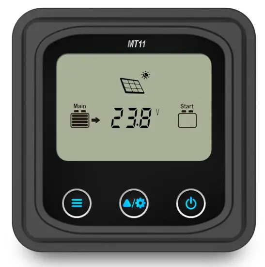
Important Safety Instructions
Thank you for selecting the remote meter.
General safety information
- Please contact our company or transportation if the product has been damaged.
- Please read this manual carefully before using the product and pay attention to the safety information.
- Keep the product away from rain, exposure, severe dust, vibrations, corrosive gas and intense electromagnetic interference.
- Do not allow water to enter the product.
- There are no user serviceable parts inside the product. Do not disassemble or attempt to repair it.
Recommendations
- The MT11 is only allowed to connect with DR-N series charge controller. Please confirm before purchase and installation.
- Please do not install MT11 in a situation with strong electromagnetic interference.
Overview
The MT series remote meter is an accessory which is compatible with the DuoRacer series controller. It can monitor the running data and working status of the controller via the remote meter. The remote meter can browse the controller’s parameters, set the battery type and temperature unit, and clean the generated energy. It is suitable for RV, Camper, Boat, and so on.
Features:
- Automatically identify and display the type, model and relevant parameter data of controllers.
- Real-time display the operational data and working status of the connected devices in digital, graphics and textual forms by a large-screen multifunction LCD.
- Three touch buttons are easy and quick to operate.
- No need for external power supply. Charge controller supplies the power for MT11.
- It can browse the controller’s parameters, set the battery type and temperature unit, and clean the generated energy.
- Real-time display of failure information of the connected devices.
- Longer communication distance based on RS485.
Product classification
- MT11(include the 1.5m communication cable)
- Remote meter MT11
- 1.5m communication cable (Model: CC-RS485-RS485-3.81-4P-150)
- Base of MT11
- MT11 (include the 5m communication cable)
- Remote meter MT11
- 5m communication cable (Model: CC-RS485-RS485-3.81-4P-500)
- Base of MT11
- MT11 (include the 10m communication cable)
- Remote meter MT11
- 10m communication cable (Model:CC-RS485-RS485-3.81-4P-1000)
- Base of MT11
- MT11(Do not include the communication cable)
- Remote meter MT11
- 1.5m communication cable (Model: CC-RS485-RS485-3.81-4P-150)
- Do not include Base of MT11
NOTE: The user can purchase the product according to the requirement.
Installation
Base of MT11 (Optional accessory)
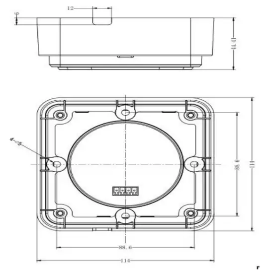
| Mechanical parameter | Parameter |
| Overall dimension | 114 x 114 x 44.41mm |
| Mounting dimension | 88.6 x 88.6mm |
| Terminal | Φ5 |
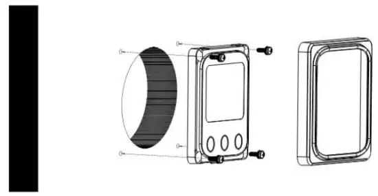
Wall installation steps
- Step1: Locate and drill screw holes based on the Frame Mounting dimension of the base, and erect the plastic expansion bolts.
- Step2: Use four PA4.2×32 self-tapping screws to fix the Frame.
- Step3: Remove the decorative shell.
- Step4: Use four M4×8 pan head screws to mount MT11 Surface on the Frame.
- Step5: Install the decorative shell.

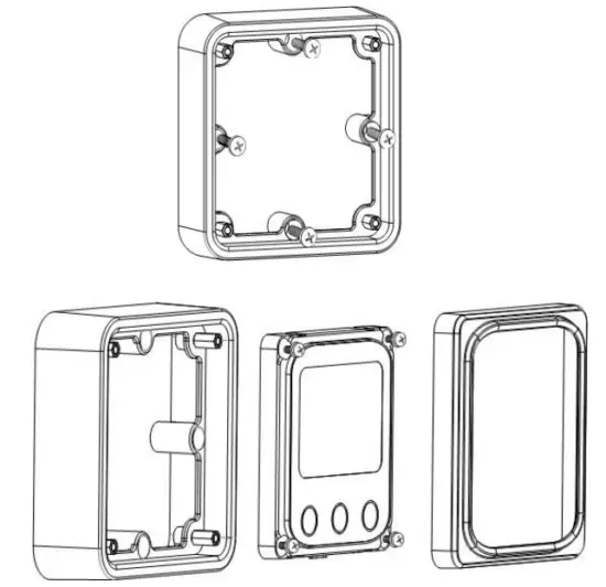
Surface mounting steps
- Step1: Locate and drill screw holes based on the installation size of the surface.
- Step2: Remove the decorative shell
- Step3: Use four M4×8 cross recessed pan head screws with M4 nuts to mount MT11 surface onto the panel.
- Step4: Install the decorative shell
NOTE: Take full consideration of the plugging/unplugging space of the communication cable and the length of the cable during installation to see if they are appropriate.
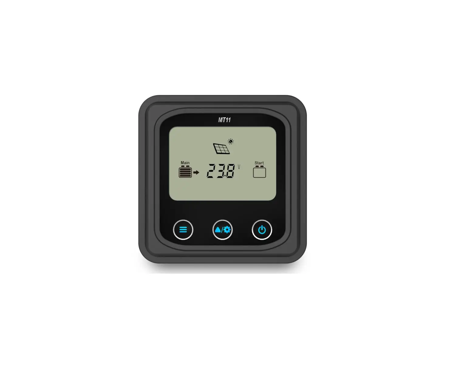
Product Features
Front View
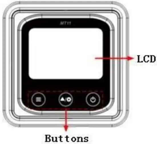
LCD display screen
Man-machine interaction operation interface. Refer to the chapter 5 Display and Operation.
Buttons
The meter buttons include two function buttons and one switch button.
| Press the button |
| |
| Press the button | Browse the PV array parameters Browse the Storage battery parameters Browse the start battery parameters | |
| Press the button and hold on 5s | Temperature units Battery type | |
| Press the button | The meter is powered ON | |
| Press the button and hold on 5s | The meter is powered OFF |
Rear View
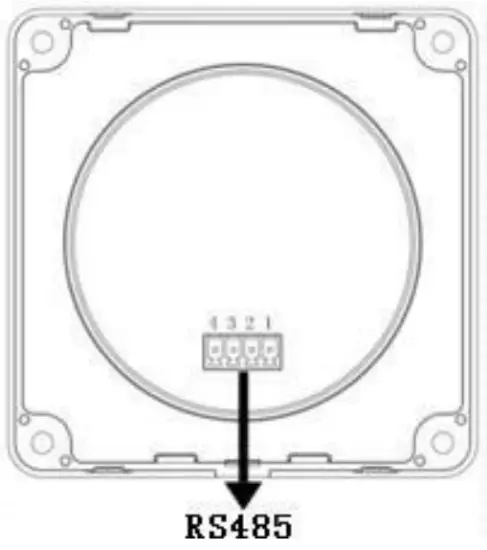
RS485 communication port
It is used to connect the controller which powers the MT11.
Communication cable’s models
CC-RS485-RS485-3.81-4P-150(Included)
CC-RS485-RS485-3.81-4P-1000(Optional)
CC-RS485-RS485-3.81-4P-2000(Optional)
Pins definition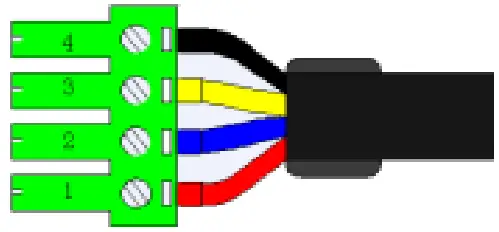
| PIN | Definition |
| 1 | DC5V |
| 2 | RS-485-B |
| 3 | RS-485-A |
| 4 | GND |
Display and Operation
LCD Display
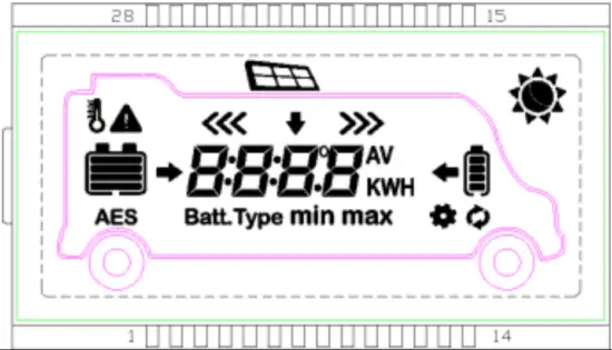
| Icon | Instruction | Icon | Instruction |
| BATT1 battery capacity level①0~12% |
| BATT2battery capacity level①0~12% |
| BATT1battery capacity level①13%~35% |
| BATT2battery capacity level①13%~35% |
| BATT1battery capacity level①36%~61% |
| BATT2battery capacity level①36%~61% |
| BATT1battery capacity level①62%~86% |
| BATT2battery capacity level①62%~86% | |
| BATT1battery capacity level① 87%~100% |
| BATT2battery capacity level① 87%~100% | |
| Day | PV array | ||
| Night |
| BATT1 charging icon |
| Display the parameters of PV |
| BATT2 charging icon |
| Display the parameters of BATT1 |
| BATT1temperature parameters |
| Display the parameters of BATT2 | AES | AES signal icon | |
 | Setting icon | Batt.Ty | Battery type icon |
| Auto global view sign | min | Minimum voltage icon |
| Fault Icon | max | Maximum voltage icon |
- Battery power capacity is calculated by the linear relationship between the disconnect voltage of low voltage and float charging voltage.
Auto Global View Mode
Operation:
- Step1: Press the
 button, Auto appears.
 - Step2: Press the
 button, select the
  .
.
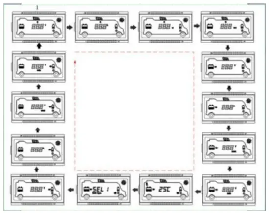
Echo Loop:PV voltage —PV current —PV power—Battery power—BATT1 voltage—BATT1 current—Max. BATT1 voltage—Min.BATT1 voltage—BATT1 temperature—BATT1 battery type—BATT2 voltage—BATT2 current—Max. BATT1 voltage—Min.BATT2 voltage—PV voltage
Temperature units
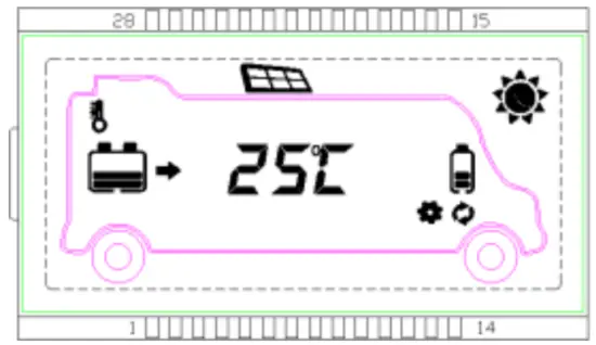
Operation:
- Step1: Press the button under the battery temperature interface.
- Step2: Press the button to select the temperature unit.
- Step3: Press the button to set successfully.
Clear the generated energy
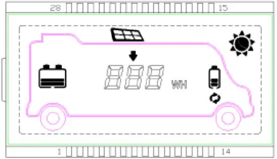
Press the ![]() and
and ![]() button and hold on 5s to clear the generated energy.
button and hold on 5s to clear the generated energy.
Battery type
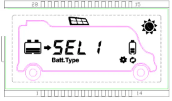
- Operation:
- Step1: Press the button and hold 5s under the battery type interface.
- Step2: Press the button when the battery type interface is flashing.
- Step3: Press the button to confirm the battery type.
- Step1: Press the
- Battery type
SEL 1 BATT112V Sealed SEL 2 BATT124V Sealed GEL 1 BATT112V Gel GEL 2 BATT124V Gel FLd 1 BATT112V Flooded FLd 2 BATT124V Flooded Li F4 LiFePO4(4S) Li F8 LiFePO4(8S) Li C3 Li-NiCoMn (3S) Li C6 Li-NiCoMn (6S) USE User
![]() CAUTION: The battery voltage is set as default and not changeable when selecting the default battery type. Please change to “User” battery type before adjusting the battery voltage.
CAUTION: The battery voltage is set as default and not changeable when selecting the default battery type. Please change to “User” battery type before adjusting the battery voltage.
![]() CAUTION: Set the voltage of the “User” battery type via PC software only.
CAUTION: Set the voltage of the “User” battery type via PC software only.
- Lead-acid Battery Control Voltage Parameters
The parameters are in the 12V system at 25 ºC. Please double the values in the 24V system.Voltage parameter\Battery type Sealed Gel Flooded User Over Voltage Disconnect Voltage 16.0V 16.0V 16.0V 9~17V Charging Limit Voltage 15.0V 15.0V 15.0V 9~17V Over Voltage Reconnect Voltage 15.0V 15.0V 15.0V 9~17V Equalize Charging Voltage 14.6V — — 14.8V 9~17V Boost Charging Voltage 14.4V 14.2V 14.6V 9~17V Float Charging Voltage 13.8V 13.8V 13.8V 9~17V Boost Reconnect Charging Voltage 13.2V 13.2V 13.2V 9~17V Low Voltage Reconnect Voltage 12.6V 12.6V 12.6V 9~17V Under Voltage Warning Reconnect Voltage 12.2V 12.2V 12.2V 9~17V Under Volt. Warning Voltage 12.0V 12.0V 12.0V 9~17V Low Volt. Disconnect Voltage 11.1V 11.1V 11.1V 9~17V Discharging Limit Voltage 10.6V 10.6V 10.6V 9~17V Equalize Duration (min.) 120 — — 120 0~180 Boost Duration (min.) 120 120 120 10~180 NOTE:
- When the battery type is sealed, gel, flooded, the adjusting range of equalizing duration is 0 to180min, and boost duration is 10 to180min.
- The following rules must be observed when modifying the value of the parameter in user battery type (factory default value is the same as sealed type):
- A. Over Voltage Disconnect Voltage > Charging Limit Voltage ≥ Equalize Charging Voltage ≥ Boost Charging Voltage ≥ Float Charging Voltage > Boost Reconnect Charging Voltage.
- B. Over Voltage Disconnect Voltage > Over Voltage Reconnect Voltage
- C. Low Voltage Reconnect Voltage > Low Voltage Disconnect Voltage ≥ Discharging Limit Voltage.
- D. Under Voltage Warning Reconnect Voltage > Under Voltage Warning Voltage ≥ Discharging Limit Voltage.
Boost Reconnect Charging voltage > Low Voltage Disconnect Voltage.
- Lithium Battery Control Voltage Parameters The parameters are in the 12V system at 25 ºC; please double the values in the 24V system.
Voltage parameter\Battery type LiFePO4 (4S) Li-NiCoMn (3S)
User Over Voltage Disconnect Voltage 15.6V 13.5V 9~17V Charging Limit Voltage 14.6V 12.6V 9~17V Over Voltage Reconnect Voltage 14.5V 12.5V 9~17V Equalize Charging Voltage 14.5V 12.5V 9~17V Boost Charging Voltage 14.5V 12.5V 9~17V Float Charging Voltage 13.8V 12.2V 9~17V Boost Reconnect Charging Voltage 13.2V 12.1V 9~17V Low Voltage Reconnect Voltage 12.4V 10.5V 9~17V Under Voltage Warning Reconnect Voltage 12.5V 11.0V 9~17V Under Volt. Warning Voltage 12.0V 10.5V 9~17V Low Volt. Disconnect Voltage 11.0V 9.3V 9~17V Discharging LimitVoltage 10.8V 9.3V 9~17V
The following rules must be observed when modifying the parameter values in User for the lithium battery.
- A.Over Voltage Disconnect Voltage>Over charging protection voltage(Protection Circuit Modules(BMS))+0.2V※;
- B.Over Voltage Disconnect Voltage>Over Voltage Reconnect Voltage=Charging Limit Voltage ≥ Equalize Charging Voltage=Boost Charging Voltage ≥ Float Charging Voltage>Boost Reconnect Charging Voltage;
- C.Low Voltage Reconnect Voltage>Low Voltage Disconnect Voltage ≥ Discharging Limit Voltage;
- D.Under Voltage Warning Reconnect Voltage>Under Voltage Warning Voltage≥ Discharging Limit Voltage;
- E.Boost Reconnect Charging voltage> Low Voltage Reconnect Voltage;
- F.Low Voltage Disconnect Voltage ≥ Over-discharging protection voltage (BMS)+0.2V.
![]() WARNING: The voltage parameters of the lithium battery can be set, but you must refer to the voltage parameters of lithium battery BMS.
WARNING: The voltage parameters of the lithium battery can be set, but you must refer to the voltage parameters of lithium battery BMS.
![]() WARNING: The required accuracy of BMS shall be at least 0.2V. If the deviation is higher than 0.2V, the manufacturer will assume no liability for any system malfunction caused by this.
WARNING: The required accuracy of BMS shall be at least 0.2V. If the deviation is higher than 0.2V, the manufacturer will assume no liability for any system malfunction caused by this.
Fault indication
| Fault | Fault indicator | Charge indicator | LCD | Instruction |
| BATT2 over voltage | Red Fast flashing | _ | Battery level shows full, battery frame blink, fault icon blink. | |
| BATT2 over- discharged | _ | _ | Battery level shows empty, battery frame blink, fault icon blink. | |
| BATT2 over temperature | Red Fast flashing | _ | Battery level shows current capacity, battery frame blink, fault icon blink, the temperature icon blink. | |
| BATT2 system erro T1 1 | Red Fast flashing | Green Fast flashing | Battery level shows empty, battery frame blink. |
Technical Specifications
| Model | MT11 |
| Apply to model | DRN series |
| Self-consumption(Power on) | 13mA/5Vdc |
| Self-consumption(Power off) | 4mA |
| Communication way | RS485 |
| Communication port | 3.81-4P |
| RS485 cable | CC-RS485-RS485-3.81-4P-150(1.5m) CC-RS485-RS485-3.81-4P-500(5m) CC-RS485- RS485-3.81-4P-1000(10m) |
| Environment temperature | -20℃~+70℃ |
| Storage temperature range | -20℃~+70℃ |
| Enclosure | IP20 |
| Dimension | 98.4×98.4mm |
| Base cover dimension | 114×114mm |
| Weight | 0.11kg |

SolarV GmbH
www.solarv.de
[email protected]
Copyright © 2021 SolarV GmbH

References
 SolarV| Hochwertiges Solarmodul für Stromversorgung, Laderegler, Spannungswandler, Batterien, Wechselrichter und Zubehör. | enjoysolar®–Hochwertige Solarmodule von 5Wp bis 300 Wp Mono ,Poly oder Flexibel Module. Laderegler oder Wechselrichter mit optionale
-
SolarV| Hochwertiges Solarmodul für Stromversorgung, Laderegler, Spannungswandler, Batterien, Wechselrichter und Zubehör. | enjoysolar®–Hochwertige Solarmodule von 5Wp bis 300 Wp Mono ,Poly oder Flexibel Module. Laderegler oder Wechselrichter mit optionale


