
PARADOX PCS265LTE LTE-4G-3G-2G-GSM Communication Module
You must use a SIM card with a data charge limit. Paradox will not be responsible in any way for any usage charges of data or voice whatsoever.
Installation
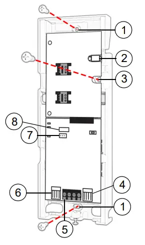
- Mounting hole
- Antenna connector
- Wall tamper hole
- Serial connector
- RS485 / power terminal
- Upgrade connector
- Battery terminal
- Cover tamper switch
SIM Card Connection
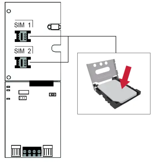
The PCS265LTE supports two nano LTE/4G/3G/2G or GSM provider SIM cards. To install the SIM cards, open the SIM Card tray and insert card into base, as shown. SIM 1 is used as “Primary” and SIM 2 for “Backup”. If only one SIM card is used, insert into SIM 1.
Note: SIM Card 2 can only be configured via SMS.
Panel Connections
Connect the PCS265LTE’s serial out to the serial connector on the panel.
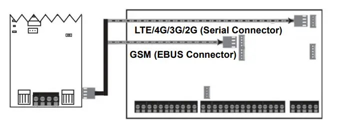
- For LTE/4G/3G/2G reporting, connect to the Serial port of the panel.
- For GSM reporting, connect to the EBUS port of the panel.
Note: GSM reporting is not supported on + Series panels.
RS485 Connection
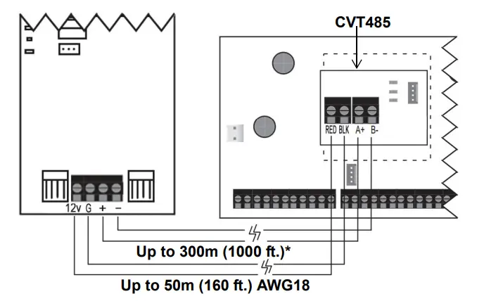
A CVT485 module can be connected onto the control panel’s EBUS in order to lengthen the distance (up to 300 m. / 1000 ft.) between the panel and the PCS265LTE. Refer to the drawing for connections.
External Antenna Connection
Use the ANTK4G LTE external antenna kit for PTCRB installations or to improve RF reception if your module’s signal strength is weak. External antenna kits and extension kits are purchased separately.
IP Module Connection
The PCS265LTE can be connected to an IP Internet Module’s PCS port. For more information on how to configure this option, please refer to the IP module’s Installation manual.
Powering-up the PCS265LTE
Once your hardware connections are completed, the PCS265LTE module will begin its power up sequence.
- Power LED will turn solid green
- Status LED will turn solid green
- SIM card 1 LED will slowly flash red while searching for the GSM network; once found the LED will be solid yellow If configured for LTE/4G/3G/2G reporting, you will need to configure network provider information. Refer to the Programming section.
Note: The battery is optional. If a battery is used/installed, do not allow the battery to deplete and ensure that the battery is replaced when low. The battery function is to support power shut down and not to be used as backup as defined in EN50131-6.
LED Functionality
| LED | Functionality | |
|
SIM1 and SIM2* | Solid yellow | GSM |
| Red flashing | No network | |
| Solid blue | LTE/4G Internet present, polling to SWAN and received a connection identifier | |
| Flashing Blue | Data exchange | |
| Solid green | 3G/2G Internet present, polling to SWAN and received a connection identifier | |
| Flashing green | Data exchange/updating firmware | |
| Flashing every 0.2 seconds | Internet present, polling to SWAN but did not receive a connection identifier | |
| Flashing every 0.5 seconds | Internet present, received a connection identifier but it is not polling to SWAN | |
| Flashing every 1 second | Internet present, not polling to SWAN and did not receive a connection identifier | |
| Off | No Internet connection | |
| Power | Solid green | Power on |
| Off | No power | |
| Status | Solid green | Battery is charged at 80% or higher |
| Flashing green | Battery charging | |
| Off | Battery is not connected | |
| Signal Strength | Three LEDs indicate network signal strength | |
When using an e-bus connection, the LED is always yellow.
Note: When upgrading the firmware remotely SIM1, SIM2, and Status LEDs will all flash green throughout the upgrade process.
Panel Communication Loss LED Functionality
| LED | Functionality | |
| SIM1 | Blue or green (LTE or 2G/3G) | On for 3 seconds then flashes green 3 times in a loop |
| SIM 2 | Orange | Flashes 3 times every 3 seconds |
| Power | Solid green | On |
| Status | Red | Flashes 3 times every 3 seconds |
| RSSI | COLOR Green | All LEDs are on for 3 seconds then off for 1.5 seconds in a loop |
Programming
In order to configure the PCS265LTE for reporting, you will need to first configure your SIM cards. Please note that SIM Card 1 can be configured via panel programming or SMS and SIM Card 2 via SMS only.
IP Reporting over LTE/4G/3G/2G and SMS Personal Reporting Network Provider Information
| MG/SP | EVO | Feature |
| [921] | [2960] | APN part 1 (characters 1-16) |
| [922] | [2961] | APN part 2 (characters 17-32) |
| [923] | [2962] | APN user name part 1 (1-16) |
| [924] | [2963] | APN user name part 2 (17-32) |
| [925] | [2964] | APN password part 1 (1-16) |
| [926] | [2965] | APN password part 2 (17-32) |
| Important: This information can be obtained from your mobile network provider. | ||
LTE/4G/3G/2G Reporting Options
| MG/SP | EVO | Feature | Details |
| [918] [919] | [2976] to [2983] | Account / Partition Registration | MG/SP: Sections represent account/ partition 1 and 2 EVO: Sections represent account / partition 1 to 8 |
| [806] | [2975] | [7] Off + [8] Off = landline only [7] Off + [8] On = LTE/4G/3G/2G primary / land- line backup (default) [7] On + [8] Off = landline only [7] On + [8] On = landline and LTE/4G/3G/2G in parallel | |
| Receiver Settings | MG/SP | |||
| Receiver #: IP address* IP port ** IP address WAN 2 IP port WAN2 Receiver password Security Profile | 1 [929] [930] [931] [932] [933] [934] | 2 [936] [937] [938] [939] [940] [941] | Backup [943] [944] [945] [946] [947] [948] | |
| Module registration Press [ARM] to register | [935] | [942] | [949] | |
| Receiver Settings | EVO | |||
| Receiver #: IP address* IP port ** IP address WAN 2 IP port WAN2 Receiver password Security Profile | 1
[2984] | 2
[2986] | 3
[2988] | 4
[2990] |
| Module registration Press [ARM] to register | [2985] | [2987] | [2989] | [2991] |
| * For 1 or 2 digit numbers, add “0’s” before the digit: e.g., 138.002.043.006 ** Default = 10000 Enter [MEM] for blank space | ||||
GSM Reporting (EBUS Connection) Reporting Options
| MG/SP | EVO | Details |
| [805] | [2950] | [1] Off + [2] Off = landline only (default) [1] Off + [2] On = landline primary / GSM backup (default) [1] On + [2] Off = GSM primary / landline backup [1] On + [2] On = GSM only |
| [815] to [817] | [3071] to [3074] | Telephone numbers |
| [811] to [812] | [3061] to [3068] | Account numbers |
SMS Messages for Backup
| Command | Description |
| P[PASSWORD].SMS[GSM MODEM TELEPHONE #].[IPRS-7 PASSWORD] | Used to program the receiver’s SMS parameters |
Additional Programming Options
SMS Language
| Language | Value | Language | Value |
| English (default) | 000 | Bulgarian | 016 |
| French | 001 | Romanian | 017 |
| Spanish | 002 | Slovak | 018 |
| Italian | 003 | Chinese | 019 |
| Swedish | 004 | Serbian | 020 |
| Polish | 005 | Malay | 021 |
| Portuguese | 006 | Slovenian | 022 |
| German | 007 | Lithuanian | 023 |
| Turkish | 008 | Finnish | 024 |
| Hungarian | 009 | Estonian | 025 |
| Czech | 010 | French Canadian | 026 |
| Dutch | 011 | Belgian | 027 |
| Croatian | 012 | Latvian | 028 |
| Greek | 013 | Albanian | 029 |
| Hebrew | 014 | Macedonian | 030 |
| Russian | 015 | ||
SMS Programming
Refer to the panel’s respective user manual for more information on SMS Personal Reporting.
| Section | SMS Site Name Label | |||||||
| EVO | ||||||||
| [2954] | / | / / | / / | / / | / / | / / | / / | / / |
| MG/SP | ||||||||
| [780] | / | / / | / / | / / | / / | / / | / / | / / |
List of SMS Commands
Please note that the default password is admin.
| Command | Description |
| P[password].A[IP address].P[port number] | Used for LTE/4G/3G/2G remote access |
| P[password].IP.[call back phone number] | Used to obtain the IP address and IP port of the PCS265LTE and whether or not the “bandwidth saver” option is being used |
| P[password].RESET | Used to power cycle the PCS265LTE |
| P[password].STATUS.[phone number] | Used to obtain the signal strength, signal quality, LTE/4G/3G/2G connection status, and APN settings of the current SIM card |
| P[password]. APN1.NAME. [Access Point Name] | Used to program the SIM Card 1 APN |
| P[password]. APN1.USER. [Access Point Name] | Used to program the SIM card 1 APN User Name |
| P[password]. APN1.PSW. [Access Point Name] | Used to program the SIM card 1 APN Password |
| P[password]. APN1.CLEAR] | Used to clear the SIM Card 1 APN |
| P[password]. VAPN1.[CALL BACK PHONE NUMBER] | Used to view the SIM Card 2 Access Point Name information |
| P[password]. APN2.NAME. [Access Point Name] | Used to program the SIM Card 2 Access Point Name |
| P[password]. APN2.USER. [Access Point Name] | Used to program the SIM Card 2 Access Point User |
| P[password]. APN2.PSW. [Access Point Name] | Used to program the SIM Card 2 Access Point Password |
| Command | Description |
| P[password]. APN2.CLEAR | Used to clear the SIM Card 2 Access Point Name |
| P[password]. VAPN2.[CALL BACK PHONE NUMBER] | Used to view the SIM Card 2 Access Point Name information |
| P[password].[IP1W1/ IP1W2/ IP2W1/ IP2W2/ IP3W1/ IP3W2/ IP4W1/ IP4W2].[domain name] | Set domain name for LTE/4G/3G/2G receiver |
| P[password].[IP1W1/ IP1W2/ IP2W1/ IP2W2/ IP3W1/ IP3W2/ IP4W1/ IP4W2] .CLEAR | Clear domain name for LTE/4G/3G/2G receiver |
| C[user code].[ARM/OFF].A[area number], [area number], [area number]TO[area number] | Arm/Disarm |
| P[password].—S | Disable SWAN polling (V4.10.011 and higher) |
| P[password].+++S | Enable SWAN polling (V4.10.011 and higher) |
Certification
The following statements apply for EN 50131 and EN 50136 certification:
- Mode of operation is pass-through
- PCS265LTE must be installed and connected to an EN approved Grade 3 control panel
- Monitoring of the transmission network interface (Internet connection): In case of network/interface failure, the device sends a trouble message to the control panel which then displays it via connected keypad(s)
- Information Security is achieved by 256-bit encrypted, supervised communication (AES validation number 986) which prevents unauthorized reading or modification of messages
- Substitution Security is achieved by Information Security (as stated above), physical security (Tamper protection) and by a unique Serial Number from each device. Messages sent to the receiving station include the S/N in order to identify the substitution and alert accordingly
Technical Specifications
| Specifications | Description |
| RF Power | Class 4 (2W) @ 850/1900 MHz Class 2 (1W) @ 1800/1900 MHz UMTS 850/1900 @ 0.25W (America) UMTS 900/2100 @ 0.25W (Europe) |
| Antenna Bandwidth | 5 bands, wideband |
| Voltage Input | 12 VDC nominal |
| Consumption during GPRS/GSM transmission | 60 mA standby 300 mA maximum |
| Encryption | 128-bit (AES) |
| SMS Protocol | 7-bit (GSM: 3GPP TS 23.038/ GSM03.38) or 16-bit (UCS2 ISO/IEC10646) |
| SIM Cards | LTE/4G/3G GSM (2G – n/a for North and South America) |
| Humidity | 0 – 90% non-condensing |
| Operating Temperature | -20 – 50 °C (-4 to 122 °F) |
| Dimensions | 20.8 x 7.5 x 2 cm / 8.2 x 2.9 x 0.8 in. |
| Certifications | EN 50136-1 EN 50136-2 Grade 3 Class II EN 50131-10 ATS Category SP5 Certification Body: Applica Test and Certification |
Safety Note: This device may operate continuously in temperature of 55°C (131°F) for a maximum period of 7 days.
Warranty
The Limited Warranty Statement can be found on the website www.paradox.com/terms.
Patents
Your use of the Paradox product signifies your acceptance of these terms and conditions. The following US patents may apply 5,886,632 and 6,215,399. Other Canadian and international patents may apply.
©2022 Paradox Security Systems (Bahamas) Ltd. All rights reserved. Specifications may change without prior notice.


