![]() MEG X570S ACE MAX
MEG X570S ACE MAX
Motherboard
User Guide
MEG X570S Ace Max Gaming Motherboard
Quick Start
Thank you for purchasing the MSI® motherboard. This Quick Start section provides demonstration diagrams about how to install your computer. Some of the installations also provide video demonstrations. Please link to the URL to watch it with the web browser on your phone or tablet. You may have even link to the URL by scanning the QR code.
Installing a Processor![]() Youtube
Youtube

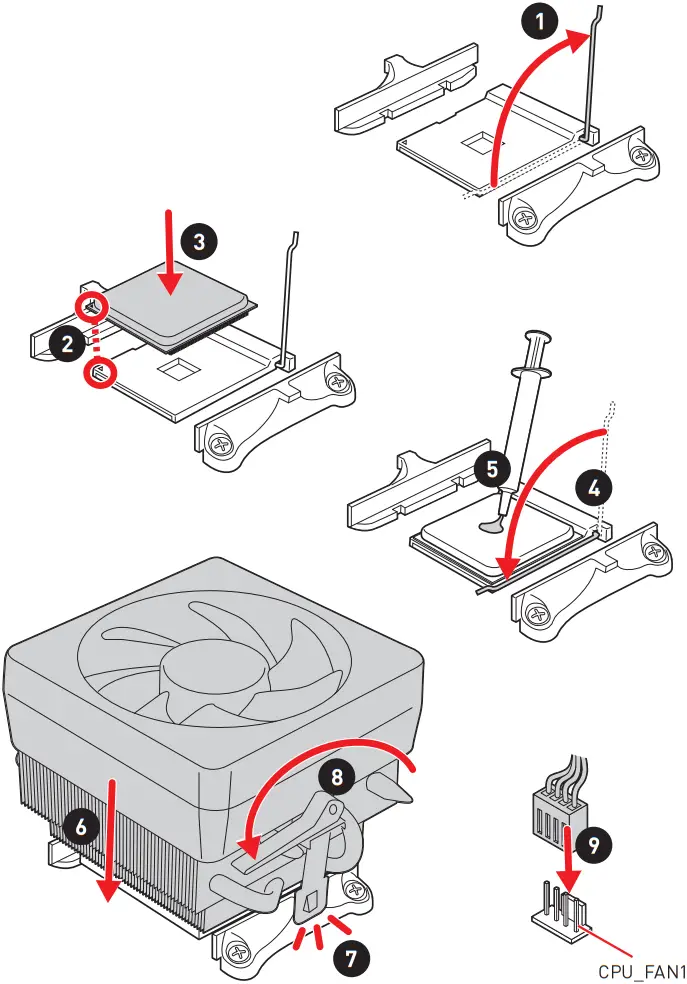
![]() Important
Important
If you are installing the screw-type CPU heatsink, please follow the figure below to remove the retention module first and then install the heatsink.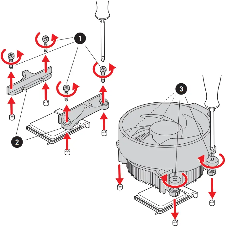 Installing DDR4 memory
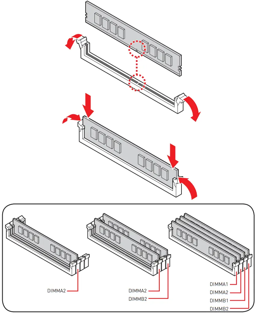

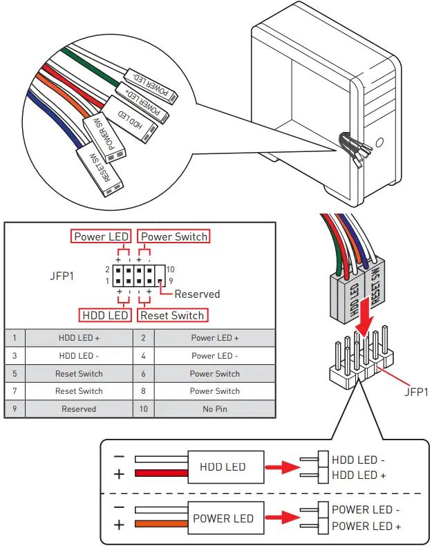
Connecting the Front Panel Header

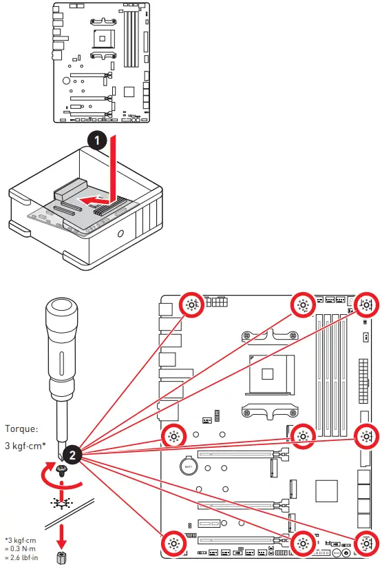
Installing the Motherboard

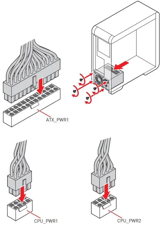
Connecting the Power Connectors

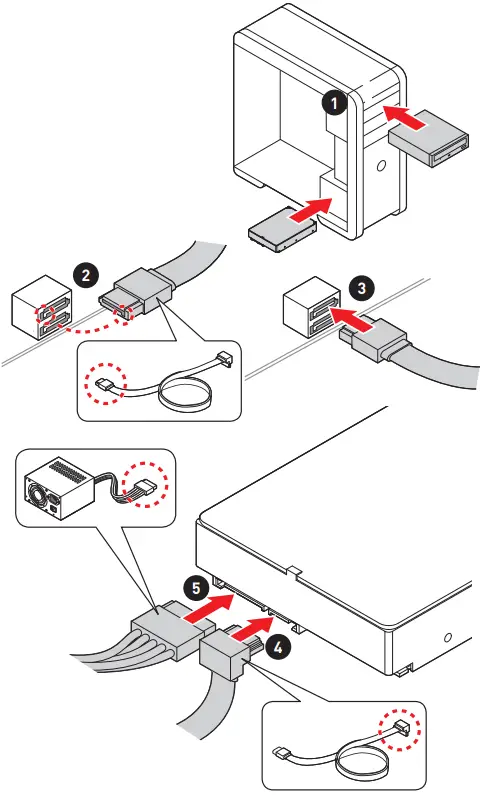
Installing SATA Drives

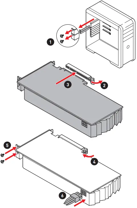
Installing a Graphics Card

Connecting Peripheral Devices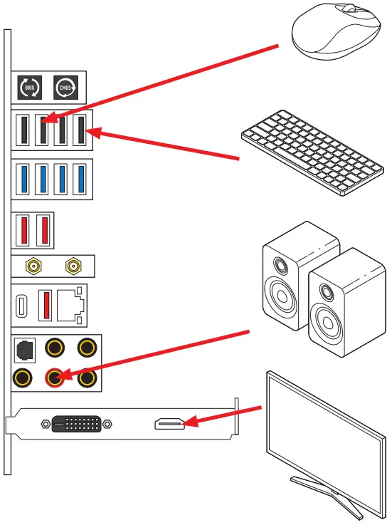 Power On
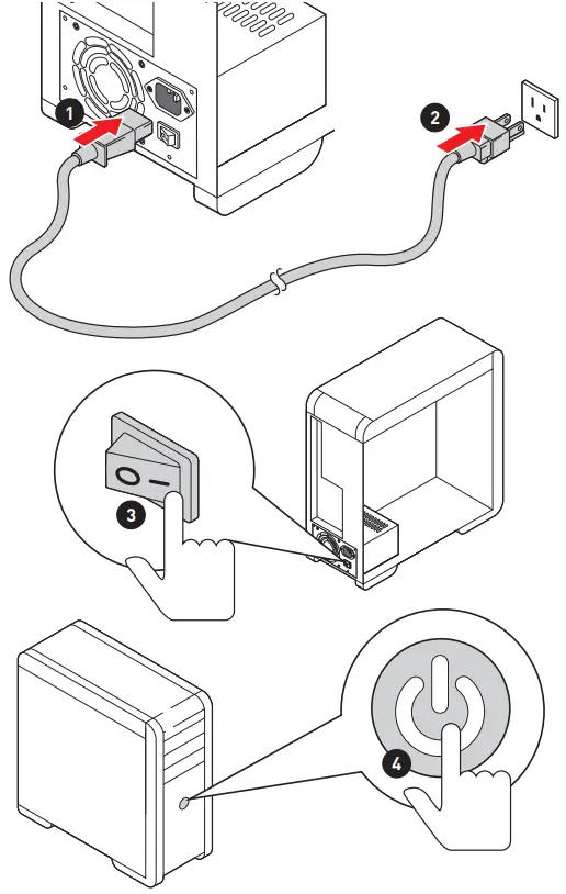
Safety Information
- The components included in this package are prone to damage from electrostatic discharge (ESD). Please adhere to the following instructions to ensure successful computer assembly.
- Ensure that all components are securely connected. Loose connections may cause the computer to not recognize a component or fail to start.
- Hold the motherboard by the edges to avoid touching sensitive components.
- It is recommended to wear an electrostatic discharge (ESD) wrist strap when handling the motherboard to prevent electrostatic damage. If an ESD wrist strap is not available, discharge yourself of static electricity by touching another metal object before handling the motherboard.
- Store the motherboard in an electrostatic shielding container or on an anti-static pad whenever the motherboard is not installed.
- Before turning on the computer, ensure that there are no loose screws or metal components on the motherboard or anywhere within the computer case.
- Do not boot the computer before installation is completed. This could cause permanent damage to the components as well as injury to the user.
- If you need help during any installation step, please consult a certified computer technician.
- Always turn off the power supply and unplug the power cord from the power outlet before installing or removing any computer component.
- Keep this user guide for future reference.
- Keep this motherboard away from humidity.
- Make sure that your electrical outlet provides the same voltage as is indicated on the PSU, before connecting the PSU to the electrical outlet.
- Place the power cord such a way that people can not step on it. Do not place anything over the power cord.
- All cautions and warnings on the motherboard should be noted.
- If any of the following situations arises, get the motherboard checked by service personnel:
▪ Liquid has penetrated into the computer.
▪ The motherboard has been exposed to moisture.
▪ The motherboard does not work well or you can not get it work according to user guide.
▪ The motherboard has been dropped and damaged.
▪ The motherboard has obvious sign of breakage. - Do not leave this motherboard in an environment above 60°C (140°F), it may damage the motherboard.
Case stand-off notification
To prevent damage to the motherboard, any unnecessary mounting stand-off between the motherboard circuits and the computer case is prohibited. The Case standoff keep out zone signs will be marked on the backside of motherboard (as shown below) to serve as a warning to user.
Avoid collision notification
Protective paint is printed around each screw hole to prevent parts from being scratched.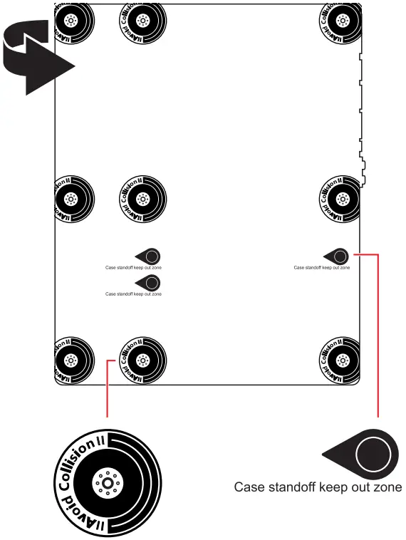
Specifications
| CPU | ∙ Supports AMD Ryzen™ 5000 Series, 5000 G-Series 4000 G-Series, 3000 Series, 3000 G-Series, 2000 Series and 2000 G-Series desktop processors* ∙ Supports Socket AM4 * Please go to msi.com to get the newest support status as new processors are released. |
| Chipset | AMD X570 Chipset |
| Memory | ∙ 4x DDR4 memory slots, support up to 128GB ∙ Supports 1866/ 2133/ 2400/ 2667/ 2800/ 2933/ 3000/ 3066/ 3200 MHz by JEDEC* ∙ Max frequency by A-XMP OC mode: ▪ For Ryzen™ 5000 G-Series & 4000 G-Series processors ▫ 1DPC 1R Max speed up to 5300 MHz (support overclocking up to 5500+ MHz) ▫ 1DPC 2R Max speed up to 4266 MHz ▫ 2DPC 1R Max speed up to 4400 MHz ▫ 2DPC 2R Max speed up to 3600 MHz ▪ For Ryzen™ 5000 Series & 3000 Series processors ▫ 1DPC 1R Max speed up to 5100 MHz ▫ 1DPC 2R Max speed up to 4000 MHz ▫ 2DPC 1R Max speed up to 4000 MHz ▫ 2DPC 2R Max speed up to 3600 MHz ∙ Supports Dual-Channel mode ∙ Supports non-ECC, un-buffered memory *Please refer to www.msi.com for more information on compatible memory |
| Expansion Slots | ∙ Supports PCIe 4.0 / PCIe 3.0 ▪ PCIe 4.0 is available only on AMD Ryzen™ 5000 Series and 3000 Series desktop processors ∙ 2x PCIe x16 slots (From processor) ▪ PCI_E1 & PCI_E2 support x16/ x0, X8/ X8 for AMD Ryzen™ 5000 Series, 5000 G-Series, 4000 G-Series, 3000 Series and 2000 Series desktop processors ▪ PCI_E1 & PCI_E2 support x8/ x0 for AMD Ryzen™ 2000 G-Series and 3000 G-Series desktop processors ∙ 1x PCIe x16 slot (From X570 chipset) ▪ PCI_E4 supports x8* ∙ 1x PCIe x1 slot (From X570 chipset)** * PCI_E4, M2_3, M2_4 and SATA5~8 share the same bandwidth. Please see the page 22 for more details. ** The PCIe x1 slot and onboard Wi-Fi module share the same bandwidth, you can not use both of them simultaneously, and the default setting is the Wi-Fi module for the system. Please disable the Onboard Wi-Fi Module Control in BIOS if you want to use the PCIe x1 slot. |
| Multi-GPU | ∙ Supports NVIDIA® SLI® Technology ∙ Supports AMD CrossFire™ Technology |
| LAN | 1x Realtek® RTL8125B 2.5 Gbps LAN controller |
| Wireless LAN & Bluetooth® | Intel® Wi-Fi 6E AX210 ∙ The Wireless module is pre-installed in the M.2 (Key-E) slot ∙ Supports MU-MIMO TX/RX, 2.4GHz/ 5GHz/ 6GHz* (160MHz) up to 2.4Gbps ∙ Supports 802.11 a/ b/ g/ n/ ac/ ax ∙ Supports Bluetooth® 5.2**, FIPS, FISMA * Wi-Fi 6E 6GHz may depend on every country’s regulations and will be ready in WIN10 21H1. ** Bluetooth 5.2 will be ready in WIN10 21H1. |
| Audio | Realtek® ALC4082 Codec + ESS SABRE9018Q2C Combo DAC/HPA ∙ 7.1-Channel High Definition Audio ∙ Supports S/PDIF output |
| Storage | ∙ 8x SATA 6Gb/s ports (From X570 chipset)* ∙ 4x M.2 slots (Key M)* ▪ Supports PCIe 4.0 / PCIe 3.0 ▫ PCIe 4.0 is available only on AMD Ryzen™ 5000 Series and 3000 Series desktop processors ▪ Support SATA 6Gbps (For M2_1, M2_3 & M2_4) ▪ M2_1 (From processor) ▫ Supports 2280/ 22110 storage devices ▪ M2_2 (From X570 chipset) ▫ Supports 2260/ 2280 storage devices ▪ M2_3* (From X570 chipset) ▫ Supports 2280/ 22110 storage devices ▪ M2_4* (From X570 chipset) ▫ Supports 2260/ 2280 storage devices * PCI_E4, M2_3, M2_4 and SATA5~8 share the same bandwidth. Please see the page 22 for more details. |
| RAID | AMD X570 Chipset ∙ Supports RAID 0, RAID 1 and RAID 10 |
| USB | AMD X570 Chipset ∙ 1x USB 3.2 Gen 2 10Gbps Type-C internal connector ∙ 4x USB 3.2 Gen 1 5Gbps ports available through internal USB connectors) ∙ 1x USB 2.0 port on the back panel ∙ Asmedia® 3241 Chipset ▪ 1x USB 3.2 Gen 2×2 20Gbps Type-C port on the back panel ∙ USB 3.0 Hub ▪ 4x USB 3.2 Gen 1 5Gbps Type-A ports on the back panel ∙ USB 2.0 Hub ▪ 7x USB 2.0 ports (3 Type-A ports on the back panel, 4 ports available through the internal USB connectors) AMD Processor ∙ 3x USB 3.2 Gen 2 10Gbps Type-A ports on the back panel |
| Back Panel Connectors | ∙ 1x Clear CMOS Button ∙ 1x Flash BIOS Button ∙ 4x USB 2.0 ports ∙ 4x USB 3.2 Gen 1 5Gbps Type-A ports ∙ 1x LAN(RJ45) port ∙ 3x USB 3.2 Gen 2 10Gbps Type-A ports ∙ 1x USB 3.2 Gen 2×2 20Gbps Type-C port ∙ 2x Wi-Fi Antenna connectors ∙ 5x OFC audio jacks ∙ 1x Optical S/PDIF Out connector |
| Internal Connectors | ∙ 1x 24-pin ATX main power connector ∙ 2x 8-pin ATX 12V power connectors ∙ 8x SATA 6Gb/s connectors ∙ 4x M.2 slots (M-Key) ∙ 2x USB 2.0 connectors (support additional 4 USB ports) ∙ 2x USB 3.2 Gen 1 5Gbps connectors (support additional 4 USB ports) ∙ 1x USB 3.2 Gen 2 10Gbps Type-C connector ∙ 1x 4-pin CPU fan connector ∙ 1x 4-pin water-pump connector ∙ 6x 4-pin system fan connectors ∙ 1x Front panel audio connector ∙ 2x System panel connectors ∙ 1x TPM module connector ∙ 1x Chassis Intrusion connector ∙ 2x 2-pin Thermal sensors connectors ∙ 1x Water Flow Meter connector ∙ 1x Tuning Controller connector |
| Buttons | ∙ 1x Power button ∙ 1x Reset button |
| Jumpers | ∙ 1x Clear CMOS jumper ∙ 1x Low temperature booting jumper ∙ 1x Safe Boot jumper |
| LED Features | ∙ 1x 4-pin RGB LED connector ∙ 2x 3-pin RAINBOW LED connectors ∙ 1x 3-pin CORSAIR connector ∙ 1x EZ LED Control switch ∙ 1x 2-Digit Debug Code LED ∙ 4x EZ Debug LEDs |
| I/O Controller | NUVOTON NCT6687D Controller Chip |
| Hardware Monitor | ∙ CPU/ System/ Chipset temperature detection ∙ CPU/ System/ Pump fan speed detection ∙ CPU/ System/ Pump fan speed control |
| Form Factor | ∙ ATX Form Factor ∙ 12 in. x 9.6 in. (30.5 cm x 24.4 cm) |
| BIOS Features | ∙ 2x 256 Mb flash ∙ UEFI AMI BIOS ∙ ACPI 6.2, SM BIOS 3.0 ∙ Multi-language |
| Software | ∙ Drivers ∙ MSI Center ∙ Nahimic ∙ MSI APP Player (Bluestack) ∙ Open Broadcaster Software (OBS) ∙ CPU-Z MSI GAMING ∙ Google Chrome™, Google Toolbar, Google Drive ∙ Norton™ Internet Security Solution |
| MSI Center Features | ∙ Duet Display ∙ Gaming Mode ∙ Creator Mode ∙ Game Highlights ∙ LAN Manager ∙ Mystic Light ∙ Ambient Link ∙ Frozr AI Cooling ∙ User Scenario ∙ True Color ∙ Live Update ∙ Monitor ∙ Super Charger ∙ Speed Up ∙ Smart Image Finder ∙ MSI Companion |
| Special Features | ∙ Audio ▪ Audio Boost 5 HD ▪ Nahimic 3 ∙ Network ▪ 2.5G LAN ▪ LAN Manager ▪ Intel WiFi ∙ Cooling ▪ All Aluminum Design ▪ Mosfet Baseplate ▪ M.2 Shield Frozr ▪ K7 thermal pad ▪ Choke Pad ▪ Pump Fan ▪ Smart Fan Control ∙ LED ▪ Mystic Light ▪ Mystic Light Extension (RGB) ▪ Mystic Light Extension (RAINBOW) ▪ Mystic Light Extension (CORSAIR) ▪ Mystic Light SYNC ▪ Ambient Link ▪ EZ LED Control ▪ EZ DEBUG LED ∙ Protection ▪ PCI-E Steel Armor ▪ Pre-installed I/O Shield ∙ Performance ▪ Lightning Gen 4 PCI-E Slot ▪ Lightning Gen 4 M.2 ▪ Multi GPU – SLI Technology ▪ Multi GPU – CrossFire Technology ▪ DDR4 Boost ▪ Core Boost ▪ Game Boost ▪ Lightning USB 20G ▪ USB 3.2 Gen 2 10G ▪ USB with Type A+C ▪ Front USB Type-C ▪ Dual CPU Power ▪ Server PCB ▪ 2oz Copper thickened PCB ∙ Experience ▪ MSI Center ▪ Duet Display ▪ Frozr AI Cooling ▪ Click BIOS 5 ▪ System Saver ▪ Flash BIOS Button |
JCORSAIR1 Connector Specification
| Supporting CORSAIR RGB Products | Maximum connection |
| Lighting PRO RGB LED Strip | 20* * 20% brightness is recommended when the number of LED strips exceeds 8. |
| HD120 RGB Fan | 6 |
| SP120 RGB Fan | 6 |
| LL120 RGB Fan | 6 |
Package contents
Please check the contents of your motherboard package. It should contain:
| Motherboard | MEG X5705 ACE MAX | |
| Documentation | Quick Installation Guide | 1 |
| Application | USB drive with drivers & utilities | 1 |
| Cable | SATA 6Gb/s Cables | 4 |
| LED JRGB Y Cable | 1 | |
| LED JCORSAIR Cable | 1 | |
| LED JRAINBOW Cable | 1 | |
| Thermistor cable | 2 | |
| Accessories | Wi-Fi Antenna | 1 |
| M.2 XPANDER-Z GEN 4 S card | 1 | |
| M.2 screw + standoff (2 sets/packl | 2 | |
| Case Badge | 1 | |
| MEG sticker | 1 | |
| SATA Cable Labels | 1 | |
| Product Registration Card | 1 | |
| Gift | Small screwdriver set | 1 |
| Small Brush | 1 | |
![]() Important
Important
If any of the above items are damaged or missing, please contact your retailer.
Rear I/O Panel
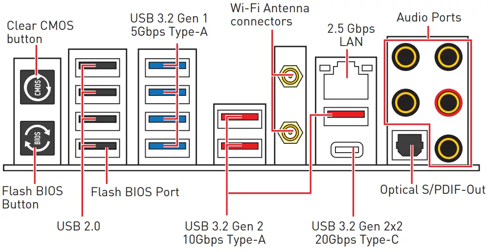
- Clear CMOS button – Power off your computer. Press and hold the Clear CMOS button for about 5-10 seconds to reset BIOS to default values.
- Flash BIOS Port/ Button – Please refer to page 49 for Updating BIOS with Flash BIOS Button.
LAN Port LED Status Table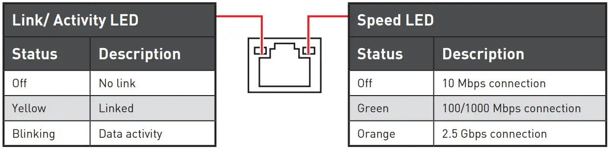 Audio Ports Configuration
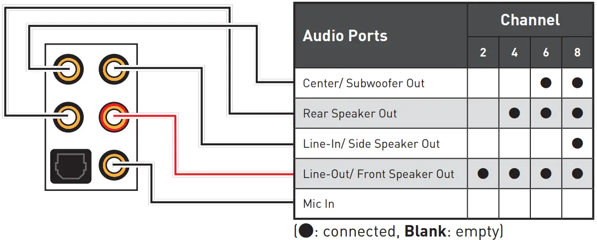 Realtek Audio Console
After Realtek Audio Console is installed. You can use it to change sound settings to get better sound experience.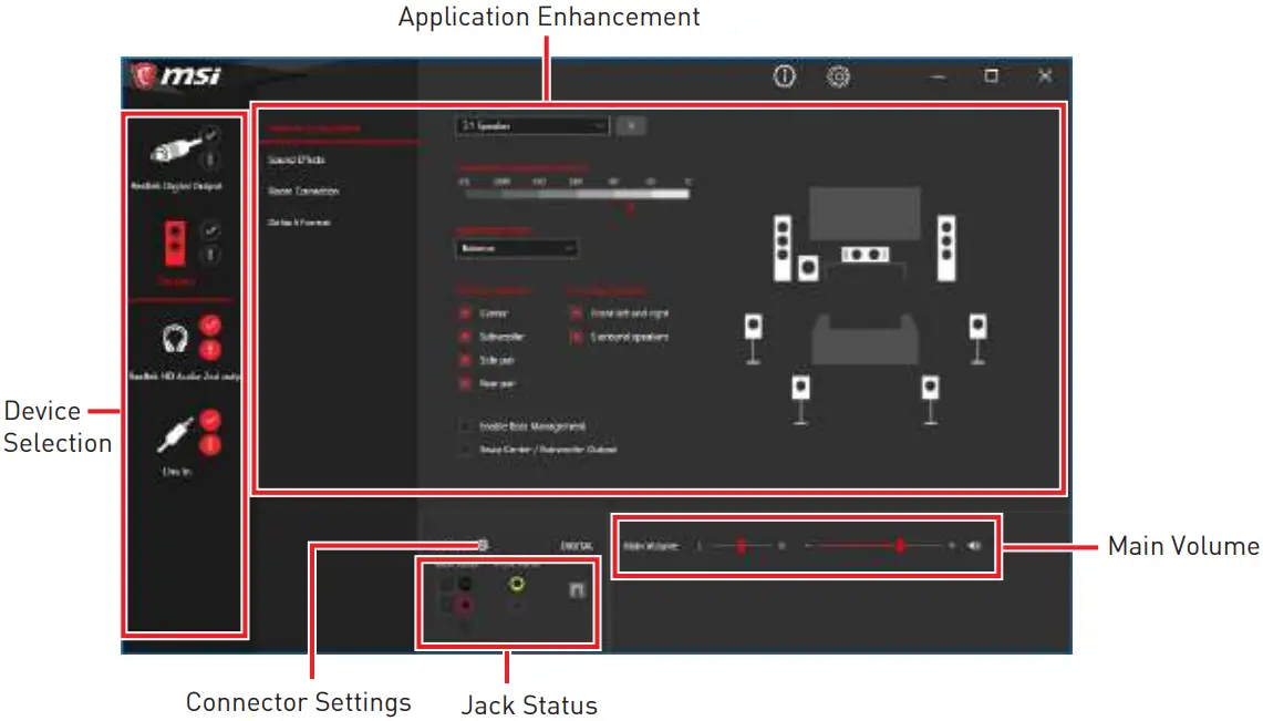
- Device Selection – allows you to select a audio output source to change the related options. The check sign indicates the devices as default.
- Application Enhancement – the array of options will provide you a complete guidance of anticipated sound effect for both output and input device.
- Main Volume – controls the volume or balance the right/left side of the speakers that you plugged in front or rear panel by adjust the bar.
- Jack Status – depicts all render and capture devices currently connected with your computer.
- Connector Settings – configures the connection settings.
Auto popup dialog
When you plug into a device at an audio jack, a dialogue window will pop up asking you which device is current connected.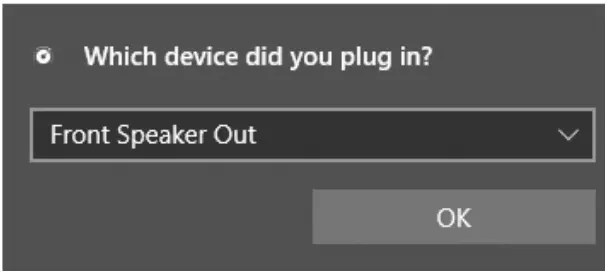 Each jack corresponds to its default setting as shown on the next page.
![]() Important
Important
The pictures above for reference only and may vary from the product you purchased.
Audio jacks to headphone and microphone diagram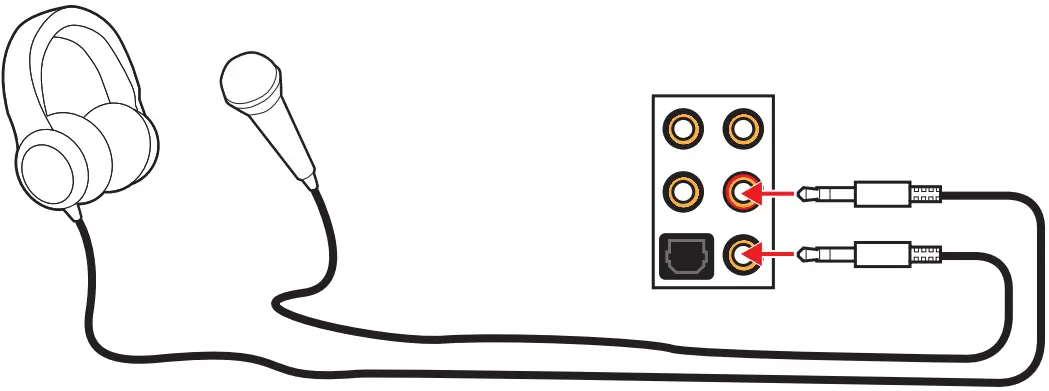 Audio jacks to stereo speakers diagram
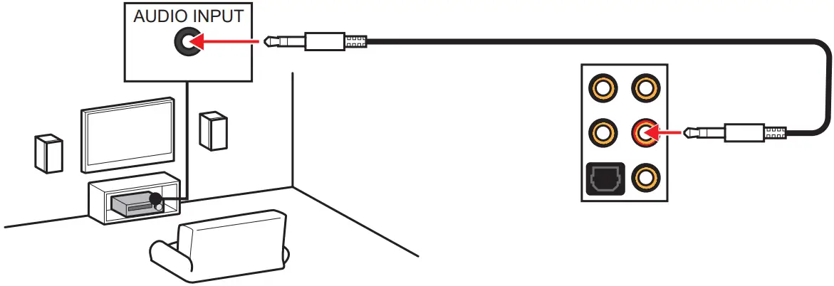 Audio jacks to 7.1-channel speakers diagram
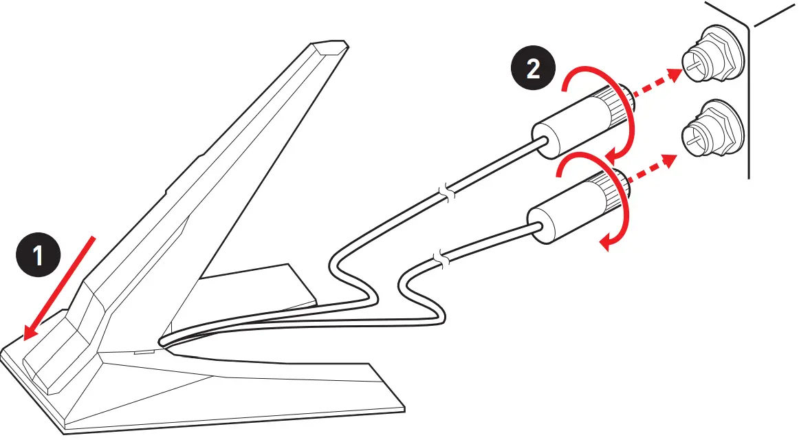
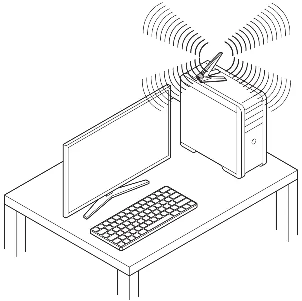
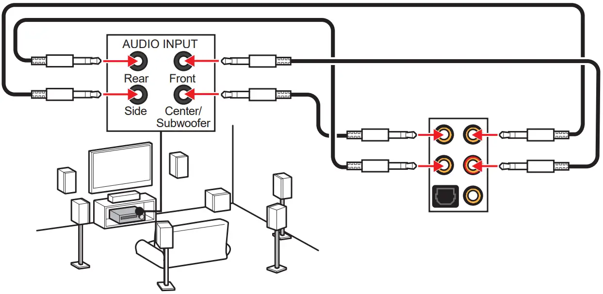 Installing Antennas
- Combine the antenna with the base.
- Screw two antenna cables tight to the WiFi antenna connectors as shown.

- Place the antenna as high as possible.

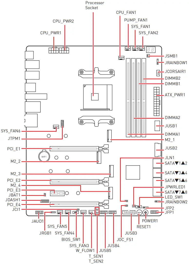
Overview of Components
 Processor Socket
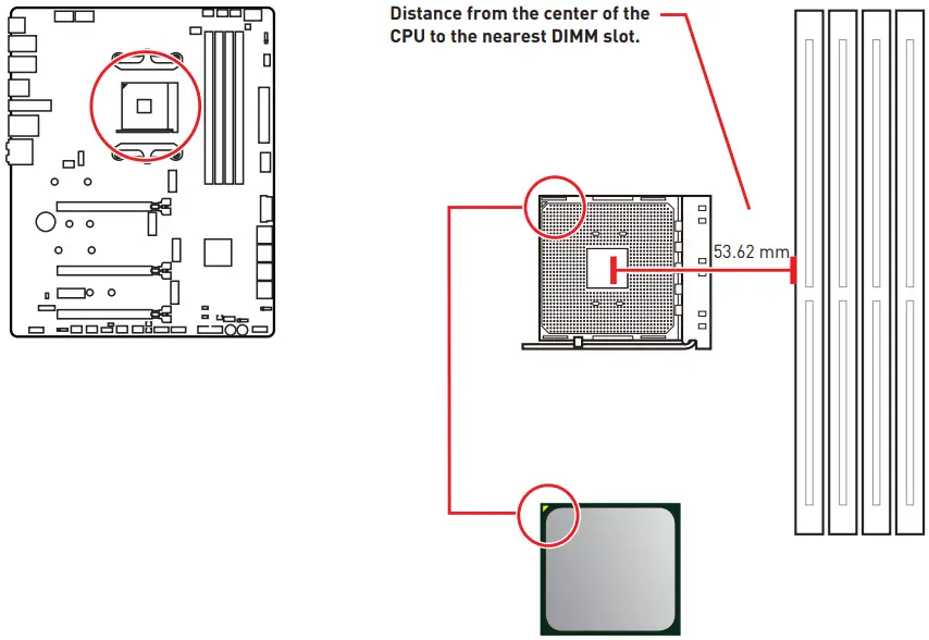 Introduction to the AM4 processor
The surface of the AM4 processor has a yellow triangle to assist in correctly lining up the processor for motherboard placement. The yellow triangle is the Pin 1 indicator.![]() Important
Important
- When changing the processor, the system configuration could be cleared and reset BIOS to default values, due to the AM4 processor’s architecture.
- Always unplug the power cord from the power outlet before installing or removing the CPU.
- When installing a CPU, always remember to install a CPU heatsink. A CPU heatsink is necessary to prevent overheating and maintain system stability.
- Confirm that the CPU heatsink has formed a tight seal with the CPU before booting your system.
- Overheating can seriously damage the CPU and motherboard. Always make sure the cooling fans work properly to protect the CPU from overheating. Be sure to apply an even layer of thermal paste (or thermal tape) between the CPU and the heatsink to enhance heat dissipation.
- If you purchased a separate CPU and heatsink/ cooler, Please refer to the documentation in the heatsink/ cooler package for more details about installation.
- This motherboard is designed to support overclocking. Before attempting to overclock, please make sure that all other system components can tolerate overclocking. Any attempt to operate beyond product specifications is not recommended. MSI® does not guarantee the damages or risks caused by inadequate operation beyond product specifications.
DIMM Slots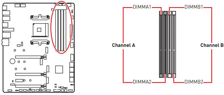 Memory module installation recommendation
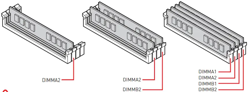
![]() Important
Important
- Always insert memory modules in the DIMMA2 slot first.
- Due to chipset resource usage, the available capacity of memory will be a little less than the amount of installed.
- Based on processor specification, the Memory DIMM voltage below 1.35V is suggested to protect the processor.
- Some memory modules may operate at a lower frequency than the marked value when overclocking due to the memory frequency operates dependent on its Serial Presence Detect (SPD). Go to BIOS and find the DRAM Frequency! to set the memory frequency if you want to operate the memory at the marked or at a higher frequency.
- It is recommended to use a more efficient memory cooling system for full DIMMs installation or overclocking.
- The stability and compatibility of installed memory module depend on installed CPU and devices when overclocking.
- Due to AM4 processor/ memory controller official specification limitation, the frequency of memory modules may operate lower than the marked value under the default state. Please refer www.msi.com for more information on compatible memory.
PCI_E1~4: PCIe Expansion Slots
| Slots | AMD Ryzen™ 5000/ 3000 series processors | AMD Ryzen™ 5000 G-/ 4000 G-/ 2000 series processors | AMD Ryzen™ 3000 G-/ 2000 G- series processors |
| PCI_E1 (CPU) | PCIe 4.0 x16 | PCIe 3.0 x16 | PCIe 3.0 x8 |
| PCI_E2 (CPU) | PCIe 4.0 x8 | PCIe 3.0 x8 | — |
| PCI_E3 (Chipset) | PCIe 4.0 x1 | PCIe 3.0 x1 | PCIe 3.0 x1 |
| PCI_E4 (Chipset) | PCIe 4.0 x8 | PCIe 3.0 x8 | PCIe 3.0 x8 |
![]() Important
Important
- If you install a large and heavy graphics card, you need to use a tool such as MSI Gaming Series Graphics Card Bolster to support its weight to prevent deformation of the slot.
- For a single PCIe x16 expansion card installation with optimum performance, using the PCI_E1 slot is recommended.
- When adding or removing expansion cards, always turn off the power supply and unplug the power supply power cable from the power outlet. Read the expansion card’s documentation to check for any necessary additional hardware or software changes.
- The PCIe x1 slot and onboard Wi-Fi module share the same bandwidth, you can not use both of them simultaneously, and the default setting is the Wi-Fi module for the system. Please disable the Onboard Wi-Fi Module Control in BIOS if you want to use the PCIe x1 slot.
PCIe bandwidth table
AMD Ryzen™ 5000 Series, 5000 G-Series, 4000 G-Series, 3000 Series and 2000 Series desktop processors
| Slot | Single VGA | 2-Way VGA | 3-Way VGA |
| PCI_E1 (CPU) | @ x16 | @ x8 | @ x8 |
| PCI_E2 (CPU) | — | @ x8 | @ x8 |
| PCI_E3 (Chipset) | x1 | x1 | x1 |
| PCI_E4 (Chipset) | x8/ x4 | x8/ x4 | @ x8/ @x4* |
(─: unavailable, @: graphics card, *: CrossFire only)![]() Important
Important
PCI_E4, M2_3, M2_4 and SATA5~8 share the same bandwidth. Please refer to the following Bandwidth share table for more details.
AMD Ryzen™ 2000 G-Series and 3000 G-Series desktop processors
| Slot | Single VGA | 2-Way VGA |
| PCI_E1 (CPU) | @ x8 | @ x8 |
| PCI_E2 (CPU) | — | — |
| PCI_E3 (Chipset) | x1 | x1 |
| PCI_E4 (Chipset) | x8/ x4 | @x8/ @x4* |
(─: unavailable, @: graphics card, *: CrossFire only)![]() Important
Important
PCI_E4, M2_3, M2_4 and SATA5~8 share the same bandwidth. Please refer to the following Bandwidth share table for more details.
Bandwidth share table
PCI_E4, M2_3, M2_4 & SATA5~8
| Slot | Bandwidth configuration | |||||||
| PCI_E4 (Chipset) | x8 | ─ | x4 | |||||
| M2_3 (Chipset) | ─ | PCIe | PCIe | SATA | SATA | ─ | ||
| M2_4 (Chipset) | ─ | PCIe | ─ | SATA | ─ | PCIe | SATA | ─ |
| SATA5~6 (Chipset) | ─ | ─ | V | V | V | ─ | V | V |
| SATA7~8 (Chipset) | ─ | ─ | V | ─ | V | ─ | ─ | V |
(─: unavailable, V: available, PCIe: M.2 PCIe device, SATA: M.2 SATA device)
M2_1~4: M.2 Slots (Key M)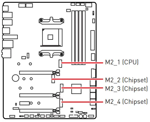

![]() Video Demonstration
Video Demonstration
Watch the video to learn how to Install M.2 SSD.
https://youtu.be/2UeWMgjwogU
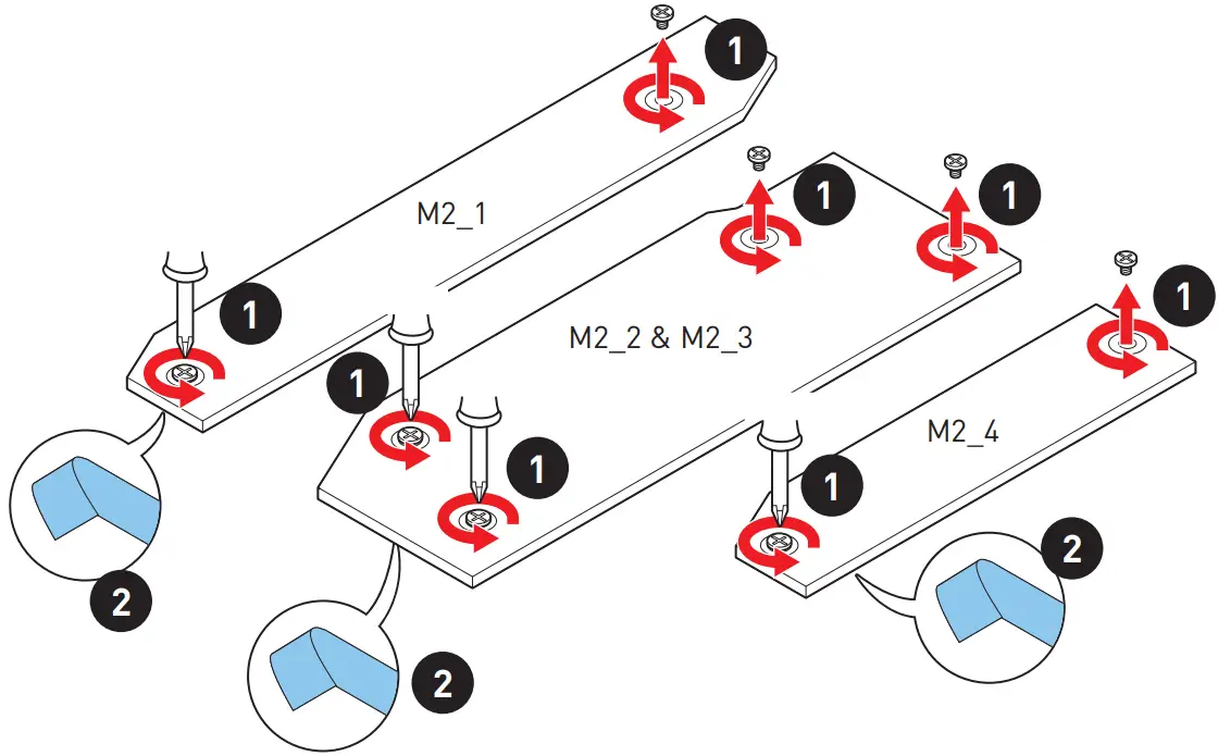
Installing M.2 module
- Loosen the screws of M.2 SHIELD FROZR heatsink.
- Remove the M.2 SHIELD FROZR and remove the protective films from the thermal pads.

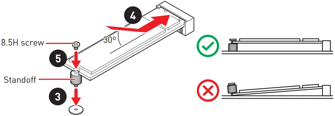
- Secure the supplied M.2 standoff according to your M.2 SSD length if need.
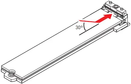
- Insert your M.2 SSD into the M.2 slot at a 30-degree angle.
- Secure the M.2 SSD in place with the supplied M.2 8.5H screw.
 Important
Skip step 3 and step 5, if you install 22110 M.2 into M2_1 & M2_3 slots or install 2280 M.2 into M2_2 & M2_4 slots.
- Put the M.2 SHIELD FROZR heatsink back in place and secure it.

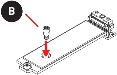
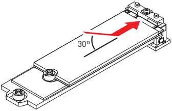
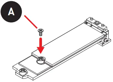
Ways to install M.2 2260 SSD into M2_2 & M2_4 slots Screws Type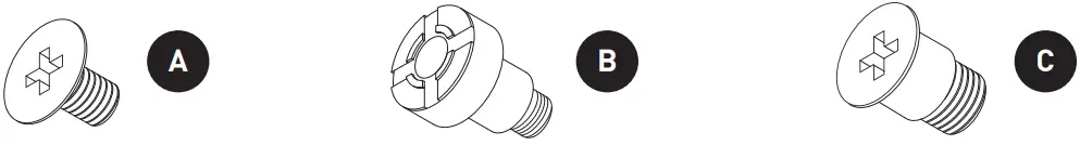
- Remove the M.2 SHIELD FROZR heatsink and remove the protective films from the thermal pads of the heatsink.
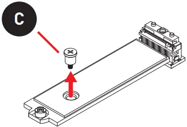
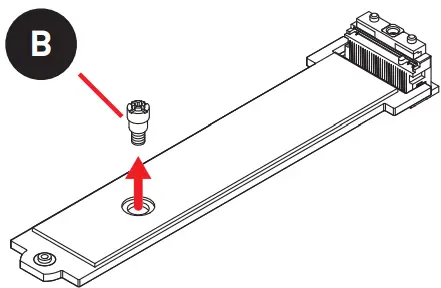
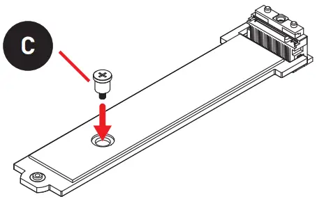
- Remove the Type-C screw.

- Tighten the Type-B screw into the M.2 plate.

- Insert the 2260 M.2 SSD into the M.2 slot at a 30-degree angle.

- Place the Type-A screw in the notch on the trailing edge of the M.2 SSD and tighten it into the Type-B screw.

- Put the M.2 SHIELD FROZR heatsink back in place and secure it.
Ways to install M.2 22110 SSD into M2_1 & M2_3 slots Screws Type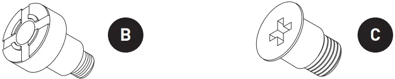
- Remove the M.2 SHIELD FROZR heatsink and remove the protective films from the thermal pads of the heatsink.
- Remove the Type-B screw.

- Tighten the Type-C screw into the M.2 plate.

- Insert the 22110 M.2 SSD into the M.2 slot at a 30-degree angle.

- Put the M.2 SHIELD FROZR heatsink back in place and secure it.
![]() Important
Important
If your M.2 SSD equips its own heatsink, please remove the M.2 plate, and then install the M.2 SSD into the M.2 slot. After complete the M.2 SSD installation, please do not re-install the M.2 SHIELD FROZR heatsink.
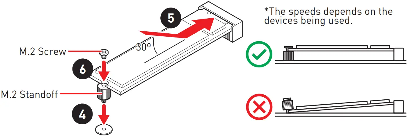
Installing M.2 XPANDER-Z Gen4 S card
To install the M.2 XPANDER-Z GEN 4 S card, please follows the steps below.
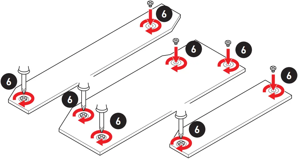
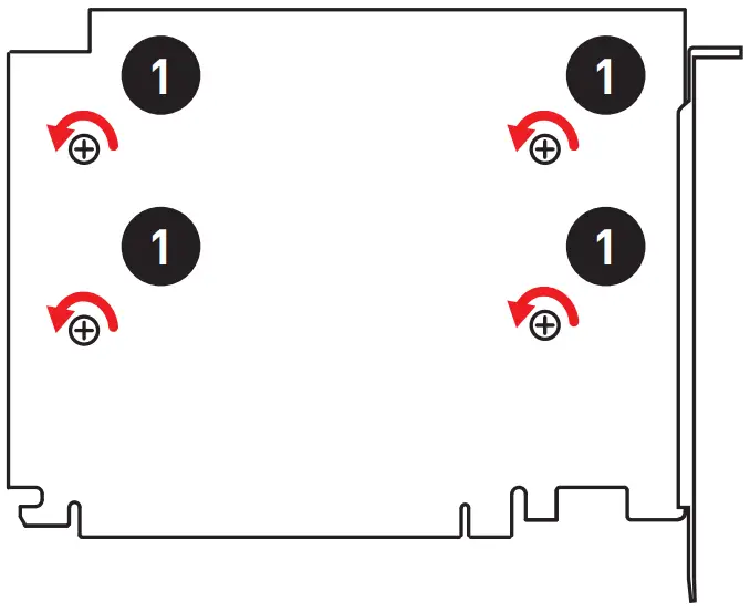
- Remove the heatsink by loosening four screws on the back of the card.

- Loosen M.2 screw from M.2 standoff.
- Loosen M.2 standoff.
- Move the position of the standoffs according to your M.2 SSDs length if need.
- Insert your M.2 SSD into the M.2 slot at a 30-degree angle.
- Secure the M.2 device in place with M.2 screw.

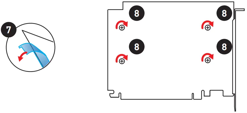
- Remove the protective film from the thermal pad of the heatsink.
- Reinstall and secure the heatsink with four heatsink screws.

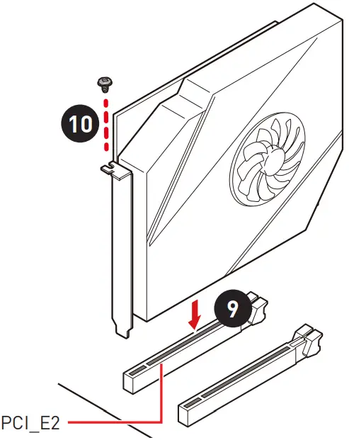
- Insert the card into the PCI_E2 slot.
- Use a screw to secure the card.

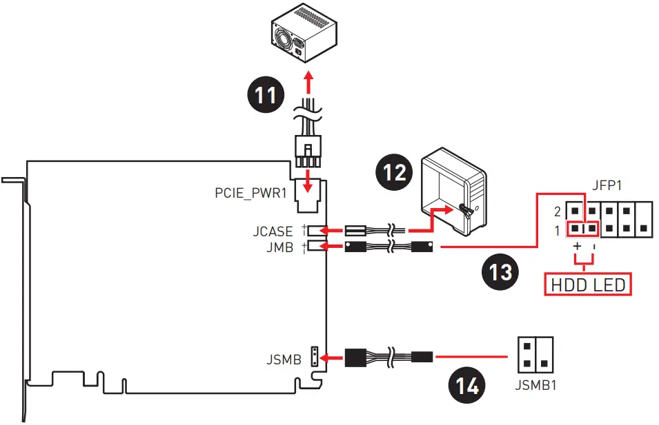
- Connect the PCIE_PWR1 to the power supply.
- Connect the case’s HDD LED cable to the JCASE connector.
- Using the supplied HDD LED cable to connect the JMB connector and JFP1’s HDD pins (pin 1 & pin3).
- Using the supplied JSMB cable to connect the JSMB connector on the card and JSMB1 connector on the motherboard. And then you can set the fan duty cycle and the LED color of the card in BIOS.

SATA1~8: SATA 6Gb/s Connectors
These connectors are SATA 6Gb/s interface ports. Each connector can connect to one SATA device.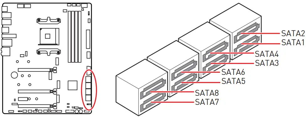
![]() Important
Important
- Please do not fold the SATA cable at a 90-degree angle. Data loss may result during transmission otherwise.
- SATA cables have identical plugs on either sides of the cable. However, it is recommended that the flat connector be connected to the motherboard for space saving purposes.
JFP1, JFP2: Front Panel Connectors
These connectors connect to the switches and LEDs on the front panel.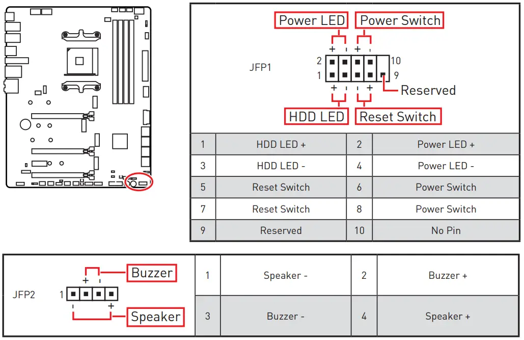 CPU_PWR1~2, ATX_PWR1: Power Connectors
These connectors allow you to connect an ATX power supply. 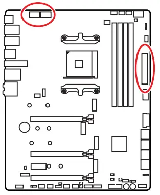
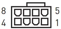 CPU_PWR1~2 CPU_PWR1~2 | |||
| 1 | Ground | 5 | +12V |
| 2 | Ground | 6 | +12V |
| 3 | Ground | 7 | +12V |
| 4 | Ground | 8 | +12V |
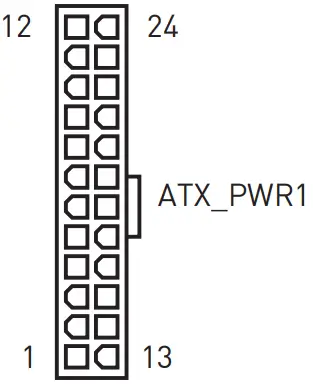
| 1 | +3.3V | 13 | +3.3V |
| 2 | +3.3V | 14 | -12V |
| 3 | Ground | 15 | Ground |
| 4 | +5V | 16 | PS-ON# |
| 5 | Ground | 17 | Ground |
| 6 | +5V | 18 | Ground |
| 7 | Ground | 19 | Ground |
| 8 | PWR OK | 20 | Res |
| 9 | 5VSB | 21 | +5V |
| 10 | +12V | 22 | +5V |
| 11 | +12V | 23 | +5V |
| 12 | +3.3V | 24 | Ground |
![]() Important
Important
Make sure that all the power cables are securely connected to a proper ATX power supply to ensure stable operation of the motherboard.
JOC_FS1: Safe Boot Jumper
This jumper is used for Safe Boot. Once enabled, the system will boot with lower PCIe (from CPU) mode.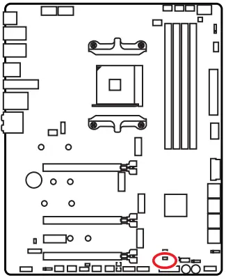
 Normal Boot Normal Boot(default) |  Enabled EnabledBoot with lower PCIe (from CPU) mode for Safe Boot. |
T_SEN1~2: Thermal Sensor Connectors
These connectors allow you to connect the thermistor cable and use it to monitor the temperature of the detection point.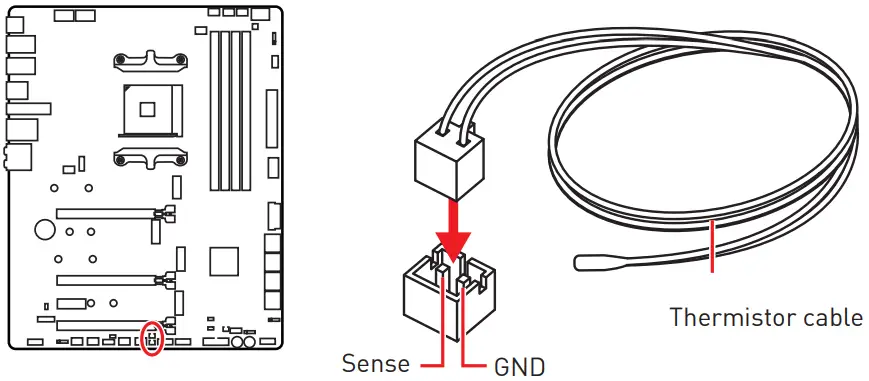 W_FLOW1: Water Flow Meter Connector
This connector allows you to connect a flow meter to monitor the flow rate of your liquid cooling system.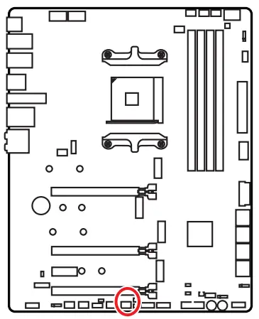
 | |||
| 1 | Ground | 3 | WFLOW IN |
| 2 | WFLOW PWR (2A) | ||
JLN1: Low Temperature Booting Jumper
This jumper is used for liquid nitrogen cooling system to boot at an extreme low temperature. Try to set it Enabled to increase the boot success rate.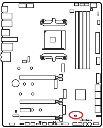
| Normal (Default) | Enabled (Please enable this jumper during BIOS POST.) |
⚠ Important
- Users will try extreme low temperature overclocking at their own risks. The overclocking results will vary according to the CPU version.
- Please don’t set to Enabled when power-off or the system will be un-bootable.
JAUD1: Front Audio Connector
This connector allows you to connect audio jacks on the front panel.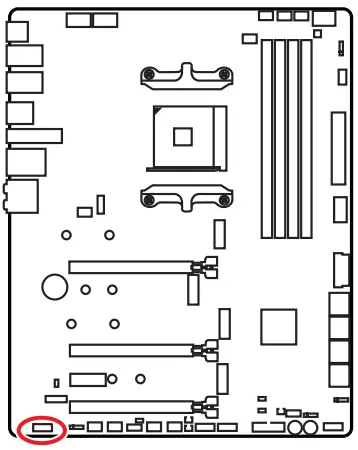

| 1 | MIC L | 2 | Ground |
| 3 | MIC R | 4 | NC |
| 5 | Head Phone R | 6 | MIC Detection |
| 7 | SENSE_SEND | 8 | No Pin |
| 9 | Head Phone L | 10 | Head Phone Detection |
JUSB1: USB 3.2 Gen 2 Type-C Connector
This connector allows you to connect USB 3.2 Gen 2 Type-C connector on the front panel. The connector possesses a foolproof design. When you connect the cable, be sure to connect it with the corresponding orientation.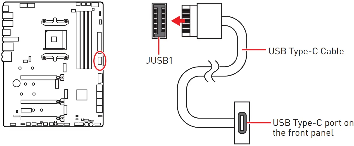 JUSB2~3: USB 3.2 Gen1 Connector
These connectors allow you to connect USB 3.2 Gen1 ports on the front panel.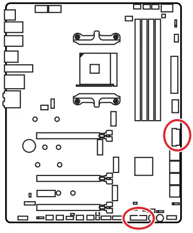
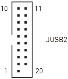 | 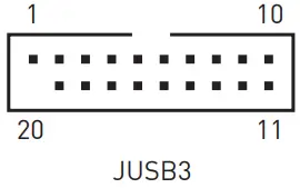 | ||
| 1 | Power | 11 | USB2.0+ |
| 2 | USB3_RX_DN | 12 | USB2.0- |
| 3 | USB3_RX_DP | 13 | Ground |
| 4 | Ground | 14 | USB3_TX_C_DP |
| 5 | USB3_TX_C_DN | 15 | USB3_TX_C_DN |
| 6 | USB3_TX_C_DP | 16 | Ground |
| 7 | Ground | 17 | USB3_RX_DP |
| 8 | USB2.0- | 18 | USB3_RX_DN |
| 9 | USB2.0+ | 19 | Power |
| 10 | NC | 20 | No Pin |
![]() Important
Important
Note that the Power and Ground pins must be connected correctly to avoid possible damage.
JUSB4~5: USB 2.0 Connectors
These connectors allow you to connect USB 2.0 ports on the front panel.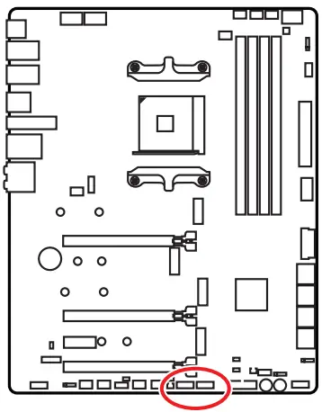
 | |||
| 1 | VCC | 2 | VCC |
| 3 | USB0- | 4 | USB1- |
| 5 | USB0+ | 6 | USB1+ |
| 7 | Ground | 8 | Ground |
| 9 | No Pin | 10 | NC |
![]() Important
Important
- Note that the VCC and Ground pins must be connected correctly to avoid possible damage.
- In order to recharge your iPad,iPhone and iPod through USB ports, please install MSI® Center utility.
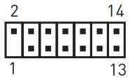
JTPM1: TPM Module Connector
This connector is for TPM (Trusted Platform Module). Please refer to the TPM security platform manual for more details and usages.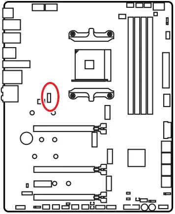
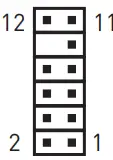 | |||
| 1 | SPI Power | 2 | SPI Chip Select |
| 3 | Master In Slave Out (SPI Data) | 4 | Master Out Slave In (SPI Data) |
| 5 | Reserved | 6 | SPI Clock |
| 7 | Ground | 8 | SPI Reset |
| 9 | Reserved | 10 | No Pin |
| 11 | Reserved | 12 | Interrupt Request |
CPU_FAN1, PUMP_FAN1, SYS_FAN1~6: Fan Connectors
Fan connectors can be classified as PWM (Pulse Width Modulation) Mode or DC Mode.
PWM Mode fan connectors provide constant 12V output and adjust fan speed with speed control signal. DC Mode fan connectors control fan speed by changing voltage.
The auto mode fan connectors can automatically detect PWM and DC mode. However, you can follow the instruction below to adjust the fan connector to PWM or DC Mode manually.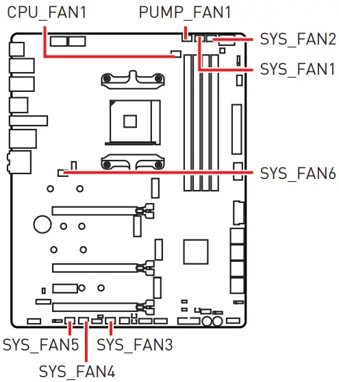
| Connector | Default fan mode | Max. current | Max. power |
| CPU_FAN1 | Auto mode | 3A | 36W |
| PUMP_FAN1 | PWM mode | 3A | 36W |
| SYS_FAN1~6 | DC mode | 2A | 24W |
Switching fan mode and adjusting fan speed
You can switch between PWM mode and DC mode and adjust fan speed in BIOS > HARDWARE MONITOR.
Select PWM mode or DC mode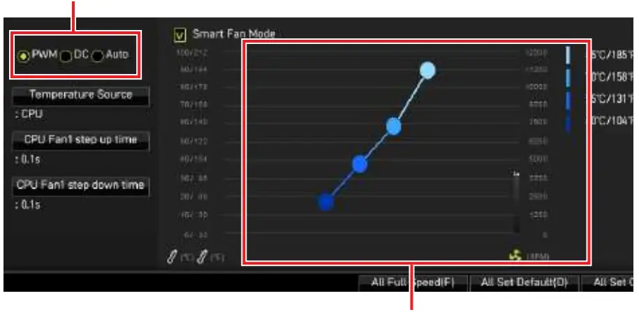 There are gradient points of the fan speed that allow you to adjust fan speed in relation to CPU temperature.
![]() Important
Important
Make sure fans are working properly after switching the PWM/ DC mode.
Pin definition of fan connectors
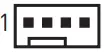 PWM Mode pin definition PWM Mode pin definition | |||
| 1 | Ground | 2 | +12V |
| 3 | Sense | 4 | Speed Control Signal |
 DC Mode pin definition DC Mode pin definition | |||
| 1 | Ground | 2 | Voltage Control |
| 3 | Sense | 4 | NC |
JCI1: Chassis Intrusion Connector
This connector allows you to connect the chassis intrusion switch cable. 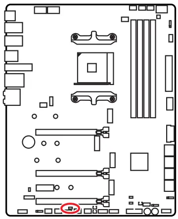
| Normal (default) | Trigger the chassis intrusion event |
Using chassis intrusion detector
- Connect the JCI1 connector to the chassis intrusion switch/ sensor on the chassis.
- Close the chassis cover.
- Go to BIOS > SETTINGS > Security > Chassis Intrusion Configuration.
- Set Chassis Intrusion to Enabled.
- Press F10 to save and exit and then press the Enter key to select Yes.
- Once the chassis cover is opened again, a warning message will be displayed on screen when the computer is turned on.
Resetting the chassis intrusion warning
- Go to BIOS > SETTINGS > Security > Chassis Intrusion Configuration.
- Set Chassis Intrusion to Reset.
- Press F10 to save and exit and then press the Enter key to select Yes.
JDASH1 : Tuning Controller connector
This connector is used to connect an optional Tuning Controller module.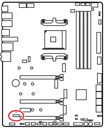
 | |||
| 1 | No Pin | 2 | NC |
| 3 | MCU_SMB_SCL_M | 4 | MCU_SMB_SDA_M |
| 5 | VCC5 | 6 | Ground |
| 7 | PSIN#_R | 8 | FP_RST#_R |
| 9 | OC_RETRY# | 10 | OC_FS |
| 11 | BLK+ | 12 | BLK- |
| 13 | CLRCMOS_EN | 14 | NC |
JBAT1: Clear CMOS (Reset BIOS) Jumper
There is CMOS memory onboard that is external powered from a battery located on the motherboard to save system configuration data. If you want to clear the system configuration, set the jumpers to clear the CMOS memory. 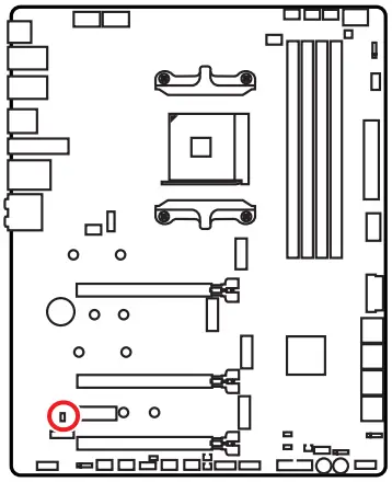
(default) |
Resetting BIOS to default values
- Power off the computer and unplug the power cord.
- Use a jumper cap to short JBAT1 for about 5-10 seconds.
- Remove the jumper cap from JBAT1.
- Plug the power cord and Power on the computer.
POWER1, RESET1: Power Button, Reset Button
The Power / Reset button allows you to power on / reset the computer.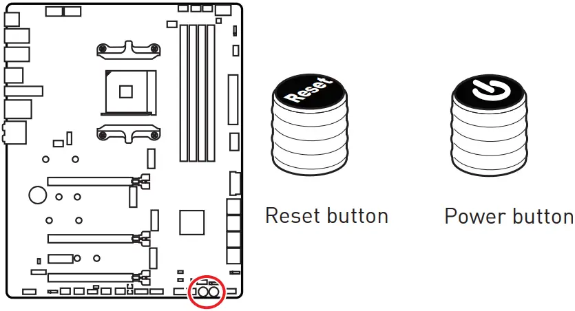 JRGB1: RGB LED connector
The JRGB connector allows you to connect the 5050 RGB LED strips 12V. 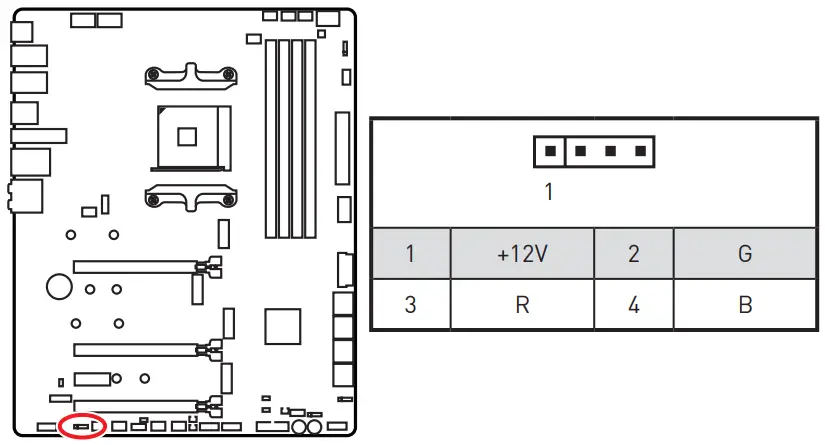 RGB LED Strip Connection
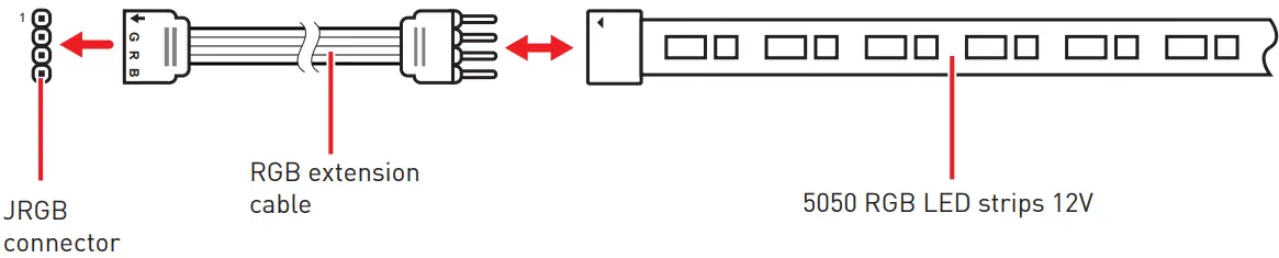 RGB LED Fan Connection
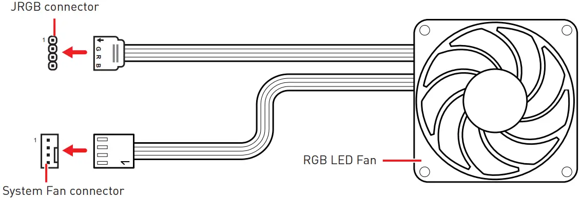
![]() Important
Important
- The JRGB connector supports up to 2 meters continuous 5050 RGB LED strips (12V/G/R/B) with the maximum power rating of 3A (12V).
- Always turn off the power supply and unplug the power cord from the power outlet before installing or removing the RGB LED strip.
- Please use MSI’s software to control the extended LED strip.
JRAINBOW1~2: Addressable RGB LED connectors
The JRAINBOW connectors allow you to connect the WS2812B Individually Addressable RGB LED strips 5V. 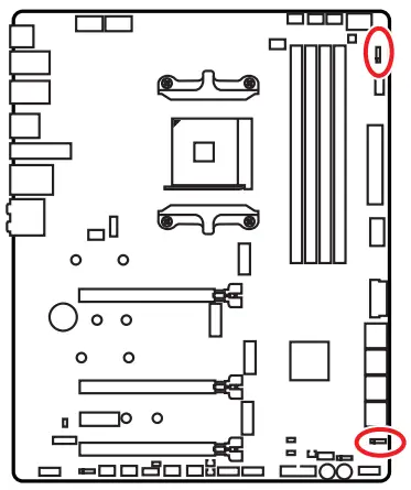
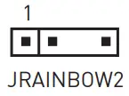 | 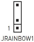 | ||
| 1 | +5V | 2 | Data |
| 3 | No Pin | 4 | Ground |
Addressable RGB LED Strip Connection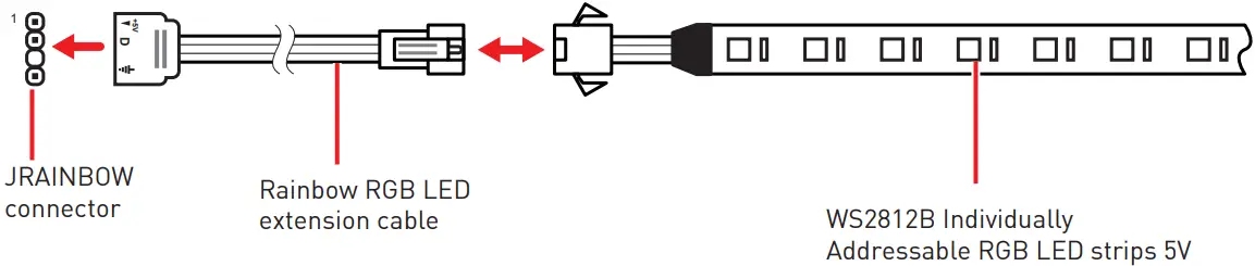 Addressable RGB LED Fan Connection
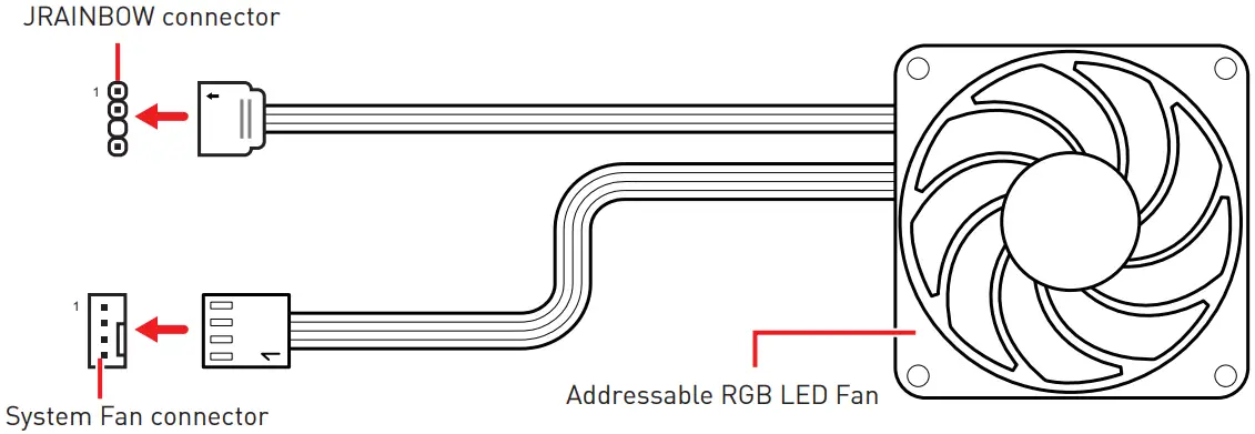
![]() CAUTION
CAUTION
Do not connect the wrong type of LED strips. The JRGB connector and the JRAINBOW connector provide different voltages, and connecting the 5V LED strip to the JRGB connector will result in damage to the LED strip.![]() Important
Important
- The JRAINBOW connector supports up to 75 LEDs WS2812B Individually Addressable RGB LED strips (5V/Data/Ground) with the maximum power rating of 3A (5V). In the case of 20% brightness, the connector supports up to 200 LEDs.
- Always turn off the power supply and unplug the power cord from the power outlet before installing or removing the RGB LED strip.
- Please use MSI’s software to control the extended LED strip.
JCORSAIR1: CORSAIR Connector
The JCORSAIR1 connector allows you to connect the CORSAIR Individually Addressable Lighting PRO RGB LED strips 5V or CORSAIR RGB fans with the CORSAIR fan hub. Once all items are connected properly, you can control the CORSAIR RGB LED strips and fans with MSI’s software. CORSAIR Lighting Node PRO Connection
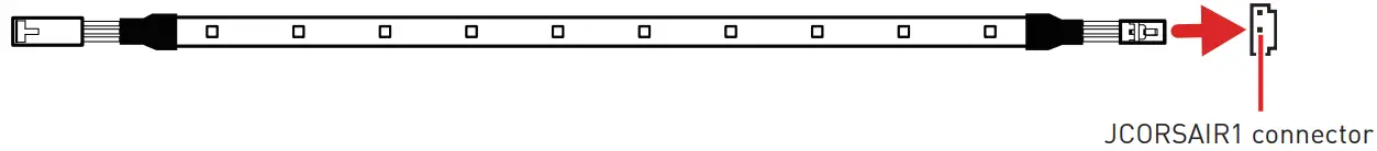
![]() Important
Important
- Fans must start at 1 and continue in series. 1 > 2 > 3 > 4 > 5 > 6. Any fan not connected in series will break communication and the RGB LED lighting function will not work.
- Quantity of RGB LED Fans or RGB LED Lighting PRO strips supported may differ between models. Please refer to the motherboard specification.
- CORSAIR RGB LED Fan and CORSAIR Lighting Node PRO can’t be used at the same time.
Onboard LEDs
EZ Debug LED
These LEDs indicate the debug status of the motherboard. 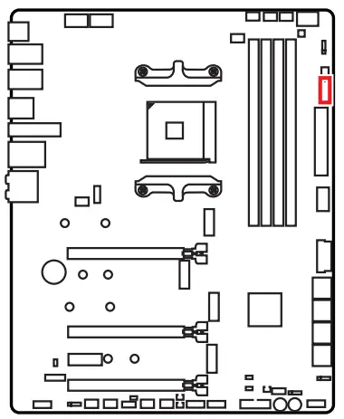
![]() CPU – indicates CPU is not detected or fail.
CPU – indicates CPU is not detected or fail.![]() DRAM – indicates DRAM is not detected or fail.
DRAM – indicates DRAM is not detected or fail.![]() VGA – indicates GPU is not detected or fail.
VGA – indicates GPU is not detected or fail.![]() BOOT – indicates the booting device is not detected or fail.
BOOT – indicates the booting device is not detected or fail.
JPWRLED1: LED power input
This connector is used by retailers to demonstrate onboard LED lights.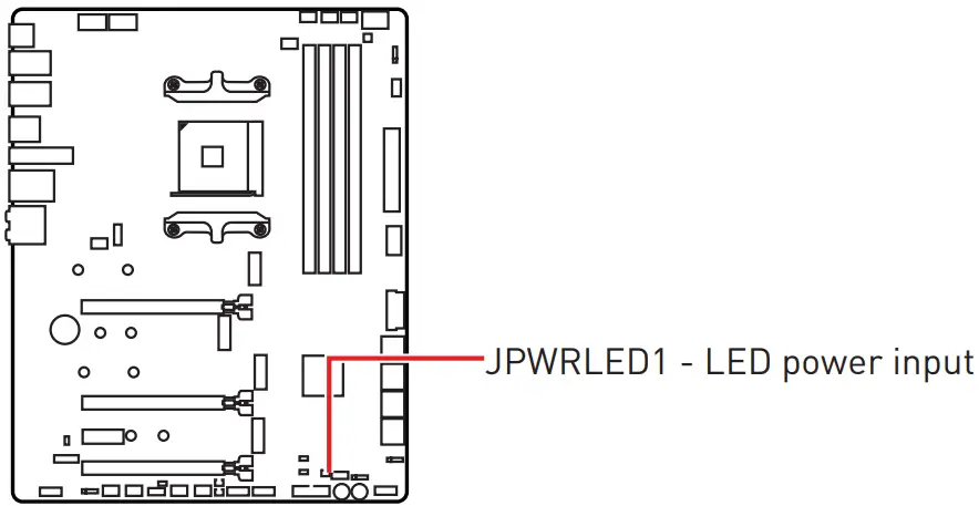
LED_SW1: EZ LED Control
This switch is used to switch on/ off all the LEDs of motherboard.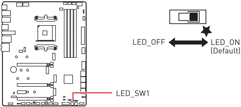 Debug Code LED
The Debug Code LED displays progress and error codes during and after POST. Refer to the Debug Code LED table for details.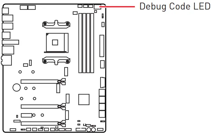 Hexadecimal Character Table
| Hexadecimal | 0 | 1 | 2 | 3 | 4 | 5 | 6 | 7 | 8 | 9 | A | B | C | D | E | F |
| Debug Code LED display |
Boot Phases
Security (SEC) – initial low-level initialization
Pre-EFI Initialization (PEI) – memory initialization
Driver Execution Environment (DXE) – main hardware initialization
Boot Device Selection (BDS) – system setup, pre-OS user interface & selecting a bootable device (CD/DVD, HDD, USB, Network, Shell, …)
Debug Code LED Table
SEC Progress Codes
| 1 | Power on. Reset type detection (soft/hard) |
| 2 | AP initialization before microcode loading |
| 3 | System Agent initialization before microcode loading |
| 4 | PCH initialization before microcode loading |
| 6 | Microcode loading |
| 7 | AP initialization after microcode loading |
| 8 | System Agent initialization after microcode loading |
| 9 | PCH initialization after microcode loading |
| 0B | Cache initialization |
SEC Error Codes
| 0C – 0D | Reserved for future AMI SEC error codes |
| 0E | Microcode not found |
| 0F | Microcode not loaded |
PEI Progress Codes
| 10 | PEI Core is started |
| 11 | Pre-memory CPU initialization is started |
| 14-14 | Pre-memory CPU initialization (CPU module specific) |
| 15 | Pre-memory System Agent initialization is started |
| 16 – 18 | Pre-Memory System Agent initialization (System Agent module specific) |
| 19 | Pre-memory PCH initialization is started |
| 1A – 1C | Pre-memory PCH initialization (PCH module specific) |
| 2B | Memory initialization. Serial Presence Detect (SPD) data reading |
| 2C | Memory initialization. Memory presence detection |
| 2D | Memory initialization. Programming memory timing information |
| 2E | Memory initialization. Configuring memory |
| 2F | Memory initialization (other) |
| 31 | Memory Installed |
| 32 | CPU post-memory initialization is started |
| 33 | CPU post-memory initialization. Cache initialization |
| 34 | CPU post-memory initialization. Application Processor(s) (AP) initialization |
| 35 | CPU post-memory initialization. Boot Strap Processor (BSP) selection |
| 36 | CPU post-memory initialization. System Management Mode (SMM) initialization |
| 37 | Post-Memory System Agent initialization is started |
| 38 – 3A | Post-Memory System Agent initialization (System Agent module specific) |
| 3B | Post-Memory PCH initialization is started |
| 3C – 3E | Post-Memory PCH initialization (PCH module specific) |
| 4F | DXE IPL is started |
PEI Error Codes
| 4B | Memory not installed (For Summit CPU) |
| E0 | Memory not installed (For Bristol CPU) |
DXE Progress Codes
| 60 | DXE Core is started |
| 61 | NVRAM initialization |
| 62 | Installation of the PCH Runtime Services |
| 63 | CPU DXE initialization is started |
| 64 – 67 | CPU DXE initialization (CPU module specific) |
| 68 | PCI host bridge initialization |
| 69 | System Agent DXE initialization is started |
| 6A | System Agent DXE SMM initialization is started |
| 6B – 6F | System Agent DXE initialization (System Agent module specific) |
| 70 | PCH DXE initialization is started |
| 71 | PCH DXE SMM initialization is started |
| 72 | PCH devices initialization |
| 73 – 77 | PCH DXE Initialization (PCH module specific) |
| 78 | ACPI module initialization |
| 79 | CSM initialization |
| 7A – 7F | Reserved for future AMI DXE codes |
| 90 | Boot Device Selection (BDS) phase is started |
| 91 | Driver connecting is started |
| 92 | PCI Bus initialization is started |
| 93 | PCI Bus Hot Plug Controller Initialization |
| 94 | PCI Bus Enumeration 32 |
| 95 | PCI Bus Request Resources |
| 96 | PCI Bus Assign Resources |
| 97 | Console Output devices connect |
| 98 | Console input devices connect |
| 99 | Super IO Initialization |
| 9A | USB initialization is started |
| 9B | USB Reset |
| 9C | USB Detect |
| 9D | USB Enable |
| 9E -9F | Reserved for future AMI codes |
| A0 | IDE initialization is started |
| A1 | IDE Reset |
| A2 | IDE Detect |
| A3 | IDE Enable |
| A4 | SCSI initialization is started |
| A5 | SCSI Reset |
| A6 | SCSI Detect |
| A7 | SCSI Enable |
| A8 | Setup Verifying Password |
| A9 | Start of Setup |
| AB | Setup Input Wait |
| AD | Ready To Boot event |
| AE | Legacy Boot event |
| AF | Exit Boot Services event |
| B0 | Runtime Set Virtual Address MAP Begin |
| B1 | Runtime Set Virtual Address MAP End |
| B2 | Legacy Option ROM Initialization |
| B3 | System Reset |
| B4 | USB hot plug |
| B5 | PCI bus hot plug |
| B6 | Clean-up of NVRAM |
| B7 | Configuration Reset (reset of NVRAM settings) |
| B8 – BF | Reserved for future AMI codes |
DXE Error Codes
| D0 | CPU initialization error |
| D1 | System Agent initialization error |
| D2 | PCH initialization error |
| D3 | Some of the Architectural Protocols are not available |
| D4 | PCI resource allocation error. Out of Resources |
| D5 | No Space for Legacy Option ROM |
| D6 | No Console Output Devices are found |
| D7 | No Console Input Devices are found |
| D8 | Invalid password |
| D9 | Error loading Boot Option (LoadImage returned error) |
| DA | Boot Option is failed (StartImage returned error) |
| DB | Flash update is failed |
| DC | Reset protocol is not available |
S3 Resume Progress Codes
| E0 | S3 Resume is stared (S3 Resume PPI is called by the DXE IPL) |
| E1 | S3 Boot Script execution |
| E2 | Video repost |
| E3 | OS S3 wake vector call |
| E4 – E7 | Reserved for future AMI progress codes |
S3 Resume Error Codes
| E8 | S3 Resume Failed |
| E9 | S3 Resume PPI not Found |
| EA | S3 Resume Boot Script Error |
| EB | S3 OS Wake Error |
| EC – EF | Reserved for future AMI error codes |
Recovery Progress Codes
| F0 | Recovery condition triggered by firmware (Auto recovery) |
| F1 | Recovery condition triggered by user (Forced recovery) |
| F2 | Recovery process started |
| F3 | Recovery firmware image is found |
| F4 | Recovery firmware image is loaded |
| F5 – F7 | Reserved for future AMI progress codes |
Recovery Error Codes
| F8 | Recovery PPI is not available |
| F9 | Recovery capsule is not found |
| FA | Invalid recovery capsule |
| FB – FF | Reserved for future AMI error codes |
ACPI States Codes
The following codes appear after booting and the operating system into ACPI modes.
| 01 | System is entering S1 sleep state |
| 02 | System is entering S2 sleep state |
| 03 | System is entering S3 sleep state |
| 04 | System is entering S4 sleep state |
| 05 | System is entering S5 sleep state |
| 10 | System is waking up from the S1 sleep state |
| 20 | System is waking up from the S2 sleep state |
| 30 | System is waking up from the S3 sleep state |
| 40 | System is waking up from the S4 sleep state |
| AC | System has transitioned into ACPI mode. Interrupt controller is in PIC mode. |
| AA | System has transitioned into ACPI mode. Interrupt controller is in APIC mode. |
Installing OS, Drivers & MSI Center
Please download and update the latest utilities and drivers at www.msi.com
Installing Windows® 10
- Power on the computer.
- Insert the Windows® 10 installation disc/USB into your computer.
- Press the Restart button on the computer case.
- Press F11 key during the computer POST (Power-On Self Test) to get into Boot Menu.
- Select the Windows® 10 installation disc/USB from the Boot Menu.
- Press any key when screen shows Press any key to boot from CD or DVD…message.
- Follow the instructions on the screen to install Windows® 10.
Installing Drivers
- Start up your computer in Windows® 10.
- Insert MSI® USB Drive into the USB port.
- Click the Select to choose what happens with this disc pop-up notification, then select Run DVDSetup.exe to open the installer. If you turn off the AutoPlay feature from the Windows Control Panel, you can still manually execute the DVDSetup.exe from the root path of the MSI USB Drive.
- The installer will find and list all necessary drivers in the Drivers/Software tab.
- Click the Install button in the lower-right corner of the window.
- The drivers installation will then be in progress, after it has finished it will prompt you to restart.
- Click OK button to finish.
- Restart your computer.
MSI Center
MSI Center is an application that helps you easily optimize game settings and smoothly use content creation softwares. It also allows you to control and synchronize LED light effects on PCs and other MSI products. With MSI Center, you can customize ideal modes, monitor system performance, and adjust fan speed.
MSI Center User Guide If you would like to know more information about MSI Center, please refer to http://download.msi.com/manual/mb/MSICENTER.pdf or scan the QR code to access.
![]() Important
Important
Functions may vary depending on the product you have.
UEFI BIOS
MSI UEFI BIOS is compatible with UEFI (Unified Extensible Firmware Interface) architecture. UEFI has many new functions and advantages that traditional BIOS cannot achieve, and it will completely replace BIOS in the future. The MSI UEFI BIOS uses UEFI as the default boot mode to take full advantage of the new chipset’s capabilities.![]() Important
Important
The term BIOS in this user guide refers to UEFI BIOS unless otherwise noted.
UEFI advantages
- Fast booting – UEFI can directly boot the operating system and save the BIOS selftest process. And also eliminates the time to switch to CSM mode during POST.
- Supports for hard drive partitions larger than 2 TB.
- Supports more than 4 primary partitions with a GUID Partition Table (GPT).
- Supports unlimited number of partitions.
- Supports full capabilities of new devices – new devices may not provide backward compatibility.
- Supports secure startup – UEFI can check the validity of the operating system to ensure that no malware tampers with the startup process.
Incompatible UEFI cases
- 32-bit Windows operating system – this motherboard supports only Windows 10 64-bit operating system.
- Older graphics card – the system will detect your graphics card. When display a warning message There is no GOP (Graphics Output protocol) support detected in this graphics card.
![]() Important
Important
We recommend that you to replace with a GOP/UEFI compatible graphics card or using integrated graphics from CPU for having normal function.
How to check the BIOS mode?
- Power on your computer.
- Press Delete key, when the Press DEL key to enter Setup Menu, F11 to enter Boot Menu message appears on the screen during the boot process.
- After entering the BIOS, you can check the BIOS Mode at the top of the screen.
BIOS Mode: UEFI
BIOS Setup
The default settings offer the optimal performance for system stability in normal conditions. You should always keep the default settings to avoid possible system damage or failure booting unless you are familiar with BIOS.![]() Important
Important
- BIOS items are continuously update for better system performance. Therefore, the description may be slightly different from the latest BIOS and should be for reference only. You could also refer to the HELP information panel for BIOS item description.
- The pictures in this guide are for reference only.
- The BIOS screens, options and settings will vary depending on your system.
Entering BIOS Setup
Press Delete key, when the Press DEL key to enter Setup Menu, F11 to enter Boot Menu message appears on the screen during the boot process.
Function key
F1: General Help list
F2: Add/ Remove a favorite item
F3: Enter Favorites menu
F4: Enter CPU Specifications menu
F5: Enter Memory-Z menu
F6: Load optimized defaults
F7: Switch between Advanced mode and EZ mode
F8: Load Overclocking Profile
F9: Save Overclocking Profile
F10: Save Change and Reset*
F12: Take a screenshot and save it to USB flash drive (FAT/ FAT32 format only).
Ctrl+F: Enter Search page
* When you press F10, a confirmation window appears and it provides the modification information. Select between Yes or No to confirm your choice.
BIOS User Guide If you’d like to know more instructions on setting up the BIOS, please refer to http://download.msi.com/manual/mb/AMDX570BIOS.pdf or scan the QR code to access.
Resetting BIOS
You might need to restore the default BIOS setting to solve certain problems. There are several ways to reset BIOS:
- Go to BIOS and press F6 to load optimized defaults.
- Short the Clear CMOS jumper on the motherboard.
- Press the Clear CMOS button on the rear I/O panel.
![]() Important
Important
Be sure the computer is off before clearing CMOS data. Please refer to the Clear CMOS jumper/ button section for resetting BIOS.
Updating BIOS
Updating BIOS with M-FLASH
Before updating:
Please download the latest BIOS file that matches your motherboard model from MSI website. And then save the BIOS file into the USB flash drive.
Updating BIOS:
- Insert the USB flash drive that contains the update file into the USB port.
- Please refer the following methods to enter flash mode.
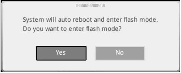
▪ Reboot and press Ctrl + F5 key during POST and click on Yes to reboot the system.
Press <Ctrl+F5> to activate M-Flash for BIOS update.
▪ Reboot and press Del key during POST to enter BIOS. Click the M-FLASH button and click on Yes to reboot the system.
- Select a BIOS file to perform the BIOS update process.
- When prompted click on Yes to start recovering BIOS.
- After the flashing process is 100% completed, the system will reboot automatically.
Updating the BIOS with MSI Center
Before updating:
- Make sure the LAN driver is already installed and the internet connection is set properly.
- Please close all other application software before updating the BIOS.
To update BIOS:
- Install and launch MSI Center and go to Support page.
- Select Live Update and click on Advance button.
- Select the BIOS file and click on Install button.
- The installation reminder will appear, then click the Install button on it.
- The system will automatically restart to update BIOS.
- After the flashing process is 100% completed, the system will restart automatically.
Updating BIOS with Flash BIOS Button
- Please download the latest BIOS file that matches your motherboard model from the MSI® website.
- Rename the BIOS file to MSI.ROM, and save it to the root of the USB storage device.
- Connect the power supply to CPU_PWR1 and ATX_PWR1. (No need to install CPU and memory.)
- Plug the USB storage device that contains the MSI.ROM file into the Flash BIOS Port on the rear I/O panel.
- Press the Flash BIOS Button to flash BIOS, and the LED starts flashing.
- The LED will be turned off when the process is completed.
Regulatory Notices![]() FCC-B Radio Frequency Interference Statement
FCC-B Radio Frequency Interference Statement
This equipment has been tested and found to comply with the limits for a Class B digital device, pursuant to part 15 of the FCC rules. These limits are designed to provide reasonable protection against harmful interference in a residential installation. This equipment generates, uses and radiates radio frequency energy, and, if not installed and used in accordance with the instructions, may cause harmful interference to radio communications. However, there is no guarantee that interference will not occur in a particular installation. If this equipment does cause harmful interference to radio or television reception, which can be determined by turning the equipment off and on, the user is encouraged to try to correct the interference by one or more of the following measures:
- Reorient or relocate the receiving antenna.
- Increase the separation between the equipment and receiver.
- Connect the equipment into an outlet on a circuit different from that to which the receiver is connected.
NOTE
- The changes or modifications not expressly approved by the party responsible for compliance could void the user’s authority to operate the equipment.
- Shield interface cables and AC power cord, if any, must be used in order to comply with the emission limits.
FCC Conditions
This device complies with part 15 of the FCC Rules. Operation is subject to the following two conditions:
- This device may not cause harmful interference.
- This device must accept any interference received, including interference that may cause undesired operation.
MSI Computer Corp.
901 Canada Court, City of Industry, CA 91748, USA
(626)913-0828
www.msi.com
CE Conformity![]() Products bearing the CE marking comply with one or more of the following EU Directives as may be applicable:
Products bearing the CE marking comply with one or more of the following EU Directives as may be applicable:
- RED 2014/53/EU
- Low Voltage Directive 2014/35/EU
- EMC Directive 2014/30/EU
- RoHS Directive 2011/65/EU
- ErP Directive 2009/125/EC
Compliance with these directives is assessed using applicable European Harmonized Standards.
The point of contact for regulatory matters is MSI, MSI-NL Eindhoven 5706 5692 ER Son.
Products with Radio Functionality (EMF)
This product incorporates a radio transmitting and receiving device. For computers in normal use, a separation distance of 20 cm ensures that radio frequency exposure levels comply with EU requirements. Products designed to be operated at closer proximities, such as tablet computers, comply with applicable EU requirements in typical operating positions. Products can be operated without maintaining a separation distance unless otherwise indicated in instructions specific to the product.
Restrictions for Products with Radio Functionality![]() CAUTION: IEEE 802.11x wireless LAN with 5.15~5.35 GHz frequency band is restricted for indoor use only in all European Union member states, EFTA (Iceland, Norway, Liechtenstein), and most other European countries (e.g., Switzerland, Turkey, Republic of Serbia). Using this WLAN application outdoors might lead to interference issues with existing radio services.
CAUTION: IEEE 802.11x wireless LAN with 5.15~5.35 GHz frequency band is restricted for indoor use only in all European Union member states, EFTA (Iceland, Norway, Liechtenstein), and most other European countries (e.g., Switzerland, Turkey, Republic of Serbia). Using this WLAN application outdoors might lead to interference issues with existing radio services.![]() Radio frequency bands and maximum power levels
Radio frequency bands and maximum power levels
- Features: Wi-Fi 6E, BT
- Frequency Range:
2412~2484MHz
5150~5350MHz (RLAN 1)
5470~5725MHz (RLAN 2)
5725~5875MHz (RLAN 3)
5875~5925MHz (RLAN 4)
5925~6425MHz - Max Power Level: 2.4 GHz: 20dBm; 5 GHz: 23dBm; 6 GHz: 23dBm
Wireless Radio Use
This device is restricted to indoor use when operating in the 2.4GHz, 5GHz, 6GHz frequency band.
Compliance Statement of Innovation, Science and Economic Development Canada (ISED)
This device complies with with Innovation, Science and Economic Development Canada’s licence-exempt RSS(s). Operation is subject to the following two conditions: (1) this device may not cause interference, and (2) this device must accept any interference, including interference that may cause undesired operation of the device. Operation in the band 5150-5250 MHz is only for indoor use to reduce the potential for harmful interference to co-channel mobile satellite systems.
CAN ICES-003(B)/NMB-003(B)
Australia and New Zealand notice
This equipment incorporates a radio transmitting and receiving device. In normal use, a separation distance of 20 cm ensures that radio frequency exposure levels comply with the Australian and New Zealand Standards.
Battery Information
European Union:![]() Batteries, battery packs, and accumulators should not be disposed of as unsorted household waste. Please use the public collection system to return, recycle, or treat them in compliance with the local regulations.
Batteries, battery packs, and accumulators should not be disposed of as unsorted household waste. Please use the public collection system to return, recycle, or treat them in compliance with the local regulations.
Taiwan:![]() For better environmental protection, waste batteries should be collected separately for recycling or special disposal.
For better environmental protection, waste batteries should be collected separately for recycling or special disposal.![]() California, USA:
California, USA:
The button cell battery may contain perchlorate material and requires special handling when recycled or disposed of in California.
For further information please visit: http://www.dtsc.ca.gov/hazardouswaste/perchlorate/
CAUTION: There is a risk of explosion, if battery is incorrectly replaced. Replace only with the same or equivalent type recommended by the manufacturer.
Chemical Substances Information
In compliance with chemical substances regulations, such as the EU REACH Regulation (Regulation EC No. 1907/2006 of the European Parliament and the Council), MSI provides the information of chemical substances in products at: https://csr.msi.com/global/index![]() Environmental Policy
Environmental Policy
- The product has been designed to enable proper reuse of parts and recycling and should not be thrown away at its end of life.
- Users should contact the local authorized point of collection for recycling and disposing of their end-of-life products.
- Visit the MSI website and locate a nearby distributor for further recycling information.
- Users may also reach us at [email protected] for information regarding proper Disposal, Take-back, Recycling, and Disassembly of MSI products.
WEEE (Waste Electrical and Electronic Equipment) Statement
ENGLISH![]() To protect the global environment and as an environmentalist, MSI must remind you that…
To protect the global environment and as an environmentalist, MSI must remind you that…
Under the European Union (“EU”) Directive on Waste Electrical and Electronic Equipment, Directive 2002/96/EC, which takes effect on August 13, 2005, products of “electrical and electronic equipment” cannot be discarded as municipal wastes anymore, and manufacturers of covered electronic equipment will be obligated to take back such products at the end of their useful life. MSI will comply with the product take back requirements at the end of life of MSIbranded products that are sold into the EU. You can return these products to local collection points.
Copyright and Trademarks Notice
Copyright © Micro-Star Int’l Co., Ltd. All rights reserved. The MSI logo used is a registered trademark of Micro-Star Int’l Co., Ltd. All other marks and names mentioned may be trademarks of their respective owners. No warranty as to accuracy or completeness is expressed or implied. MSI reserves the right to make changes to this document without prior notice.
Technical Support
If a problem arises with your system and no solution can be obtained from the user guide, please contact your place of purchase or local distributor. Alternatively, please try the following help resources for further guidance.
- Visit the MSI website for technical guide, BIOS updates, driver updates, and other information: http://www.msi.com
- Register your product at: http://register.msi.com
Revision History
- Version 1.0, 2021/06, First release.
- Version 1.1, 2022/03, updated list.
- Version 1.2, 2022/03, modify share table.
Regulatory Notices![]()


