![]() ID-7608 Verge Wall LED Mount Fixtures
ID-7608 Verge Wall LED Mount Fixtures
Instructions
Signify Classified – Internal
Wall LED Verge
ID-7608 Verge Wall LED Mount Fixtures
System Overview
These instructions review how to install Verge wall mount fixtures. Verge 4 ft and 8 ft modules can be installed as individual standalone units, or they can be joined together to create continuous rows. The graphic below shows the components required to install a typical row of Verge wall mount fixtures.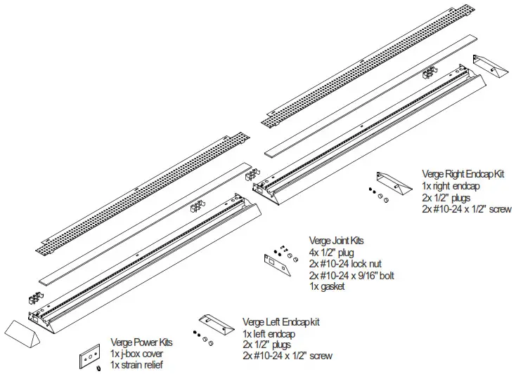
TOOLS REQUIRED: Stubby Phillips screwdriver, 3/8 ” nut driver.
Module Lengths
Sync wall mount systems come in 4ft and 8ft modules. Overall module lengths are shown to the right. Module lengths do not include endcaps. 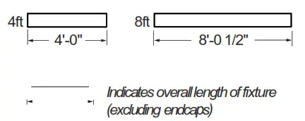
Endcaps
Add two endcaps to the overall length of each row.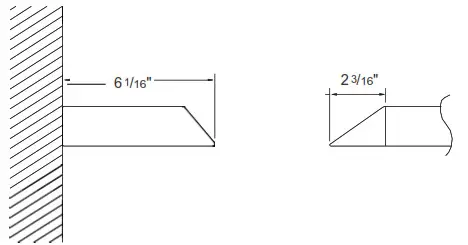
Mount Spacing
©Mounts variable within 2″ – 5″ of end or joint. On 8ft module, additional mount to be located within 2″ – 5″ of center of module.
©Maximum distance between mounts is 48″. Note: Fixture isflush with wall.
Row Configurations
The tables below indicate how 4ft and 8ft modules can be combined to create continuous rows of various lengths.
| Nominal row length | 4ft module | 8ft module |
| 4′ | 1x | |
| 8′ | 1x | |
| 12′ | 1x | 1x |
| 16′ | 2x | |
| 20′ | 1x | 2x |
| 24′ | 3x | |
| 28′ | 1x | 3x |
| 32′ | 4x |
![]() ATTENTION: Install in accordance with national and local building and electrical codes.
ATTENTION: Install in accordance with national and local building and electrical codes.
IMPORTANT: Read all instructions at least once prior to beginning installation.
All mount brackets must be secured to wall structure (eg. studs or cross-braces).
This equipment has been tested and found to comply with the limits for a Class A digital device, pursuant to part 15 of the FCC Rules. These limits are designed to provide reasonable protection against harmful interreference when the equipment is operated in a commercial environment. This equipment generates, uses, and can radiate radio frequency energy and, if not installed and used in accordance with the instruction manual, may cause harmful interference to radio communications. Operation of this equipment in a residential area is likely to cause harmful interference in which case the user will be required to correct the interference at his own expense.
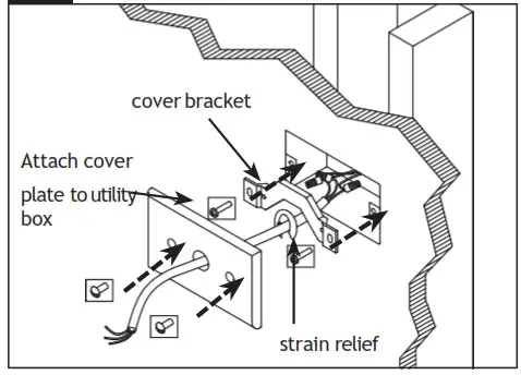
- Install utility box and utility box cover
 Determine power feed location and install 2″x4″ utility box (supplied by others) parallel with fixture. Complete connections at utility box with supplied power cord. Attach cover bracket using supplied hardware. Punch power access hole in supplied cover, feed power cord through and attach strain relief on wall side. Attach cover using supplied painted hardware. NOTE: Bottom of utility box should be in line with bottom of wall brackets.
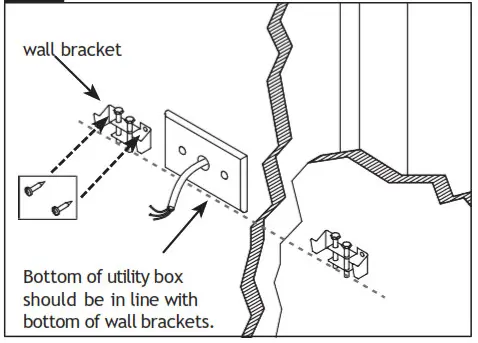
 - Install wall brackets
 Determine fixture mounting location and secure wall brackets to structure using appropriate fasteners (two per bracket, supplied by others). 4ft fixtures: Require two bracket assemblies; 8ft fixtures: Require three bracket assemblies. Brackets must be installed a maximum of 5″ from end of fixture (on 8ft fixture, the third bracket can be 5″ of ether side of inrow crossplate).
NOTE: Mounted fixture(s) will sit approximately /4″ above top edge of bracket assembly. - Unpack / Prepare fixtures
Arrange boxed fixtures on floor in specified locations; remove fixtures from boxes; remove plastic from fixtures. Cap all unnecessary power feed holes at back of fixture(s) using supplied 1/2″ plugs. - Remove Top Reflector
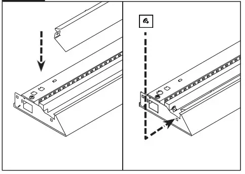
 Shift top reflector to the left and then remove the reflector.
4b Remove Front Reflector Remove the screws holding the front reflector and then remove the front reflector.
 - Raise Fixture and Engage on Wall Brackets
 With 2 people, raise fixture into position and engage it on hooks located on top of wall brackets, then rotate it down into position. Secure bracket using supplied hardware.
POWER LOCATIONS: Prior to engaging fixture in mounting brackets, feed installed power cord through the access hole at back of the fixture. - Access Wiring / Remove Pan
 To access wiring, remove screw from top pan and lift pan off. Apply strain relief to power cord.
NOTE: Care should be taken when lifting up top reflector to avoid disconnecting internal wiring. - Complete electrical connections

Complete electrical connections using wire nuts (supplied by others). Re-install pan and hardware removed in STEP 5. - Level and secure first fixture

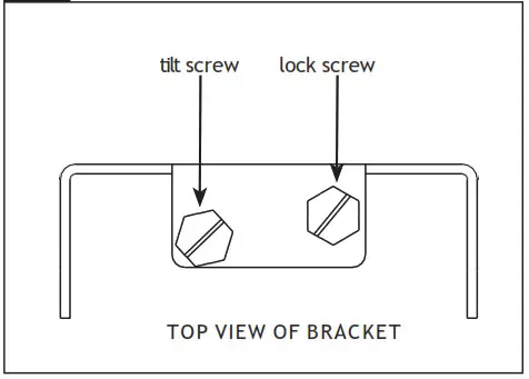
LEVEL: Using 5/16″ hex nut driver, level fixture by adjusting the tilt screw.
SECURE: Secure fixture to wall bracket assemblies by tightening the lock screw. - Install and join additional fixtures to create row

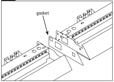
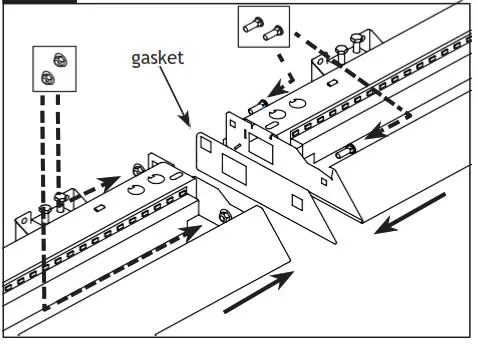
With two people, raise second fixture and engage on mounting brackets (see STEP 4). At joint, remember to insert black gasket. - Complete electrical connections at joints

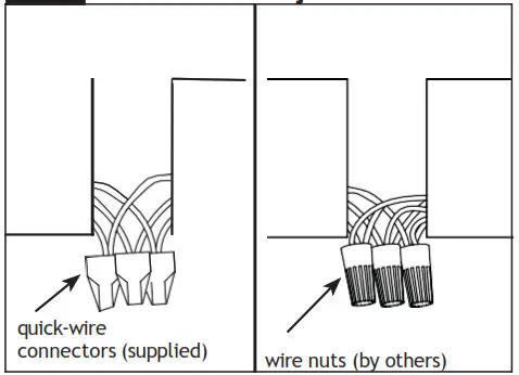
Complete in-row electrical connections.
NON-POWER LOCATIONS: Use supplied quick-wire connectors. Tuck wires into wire cavity.
POWER LOCATIONS: Remove installed quick-wire connectors and complete electrical connections using wire nuts (supplied by others). Tuck wires into wiring cavity. NOTE: Use smallest appropriate wire nuts. - Level and secure additional fixture
 Level second fixture by adjusting the tilt screw (see step 8). Slide second fixture flush against first fixture and secure joint using supplied nut and bolt hardware (requires 3/8 nut drivers). Secure fixture to wall brackets by tightening the lock screw at each bracket location (see step 8).
Repeat steps 8-10 for each additional fixture(s) in row. - Install Endcaps

Attach endcap to first and last module in each row using supplied hardware.
IMPORTANT: Do not over-tighten endcap fasteners. Ledalite recommends tightening fasteners by hand. When nut is flush with crossplate, turn an additional /4 turn. - Re-install Front Reflector
 Re-install front reflector using short (stubby) screwdriver.
 - Install Light Guide and Re-install Top Reflector

 Determine fixture mounting location and secure wall brackets to structure using appropriate fasteners (two per bracket, supplied by others). 4ft fixtures: Require two bracket assemblies; 8ft fixtures: Require three bracket assemblies. Brackets must be installed a maximum of 5″ from end of fixture (on 8ft fixture, the third bracket can be 5″ of ether side of inrow crossplate).
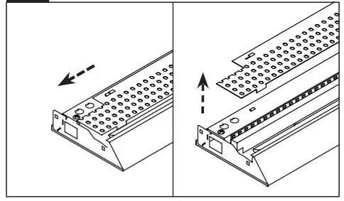 Shift top reflector to the left and then remove the reflector.
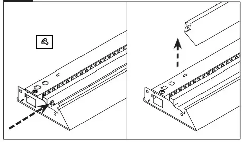 Remove the screws holding the front reflector and then remove the front reflector.
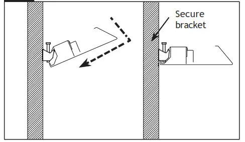 With 2 people, raise fixture into position and engage it on hooks located on top of wall brackets, then rotate it down into position. Secure bracket using supplied hardware.
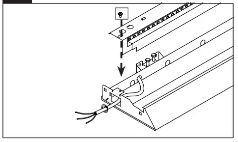 To access wiring, remove screw from top pan and lift pan off. Apply strain relief to power cord.
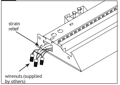
 Level second fixture by adjusting the tilt screw (see step 8). Slide second fixture flush against first fixture and secure joint using supplied nut and bolt hardware (requires 3/8 nut drivers). Secure fixture to wall brackets by tightening the lock screw at each bracket location (see step 8).
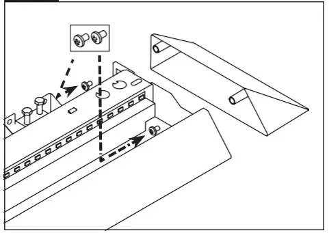
 Re-install front reflector using short (stubby) screwdriver.
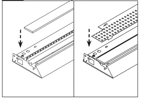
Identify smooth side of the Light Guide and ensure it is installed smooth side DOWN.
Install Light Guide panel into LED fixture after joining and wiring is complete. Ensure panel isseated correctly as shown above.
Final Step: Install the top reflector and shift into place.
Sensor in Rows
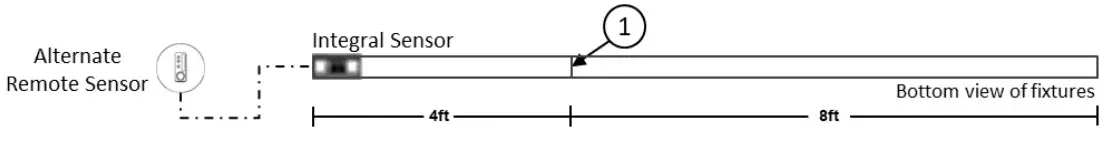
Single Sensor Controlling Whole Row
- Purple & brown (or purple & grey/pink) control wires MUST be connected between fixtures.
Note : – A maximum of 8 drivers can be wired to 8 sensors; confirm fixture driver count with factory.
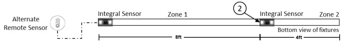
Multiple Sensors Controlling Separates Zones in a Row - Purple & brown (or purple & grey/pink) control wires MUST NOT be connected between zones.
Notes :
– A maximum of 8 drivers can be wired to one sensor; confirm fixture driver count with factory.
– Only one sensor is allowed on a wired zone. (Sensors can be paired together wirelessly via a mobile app).
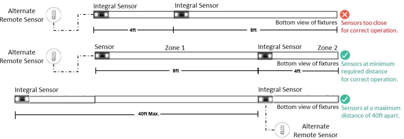
Sensor Spacing
– For correct operation, sensor should be placed a minimum distance of 8ft apart.
– Wireless sensor should be placed no further than 40ft apart for good wireless signal connection.
Important Consideration When Using Sensor in a Row
- For fixtures with wireless sensors (CS, SB or RA options):
DO NOT connect fixture purple and brown (or purple & grey/pink) control wires to an external dimming switch. Fixture mains wiring should not be connected to a circuit with an external on/off switch. - For best aesthetic condition, place sensors at ends of row only so as not to break the continuous lens.
- For better occupancy coverage in longer rows, sensors may be placed mid run, but keep in mind this will break the continuous lens into discrete sections. Alternatively, remote sensors may be used, note the same wiring rules will apply.
Occupancy Sensor Coverage:
Note: Longer dimension of detection area (Y1, Y2) is parallel to longer dimension of the luminaire.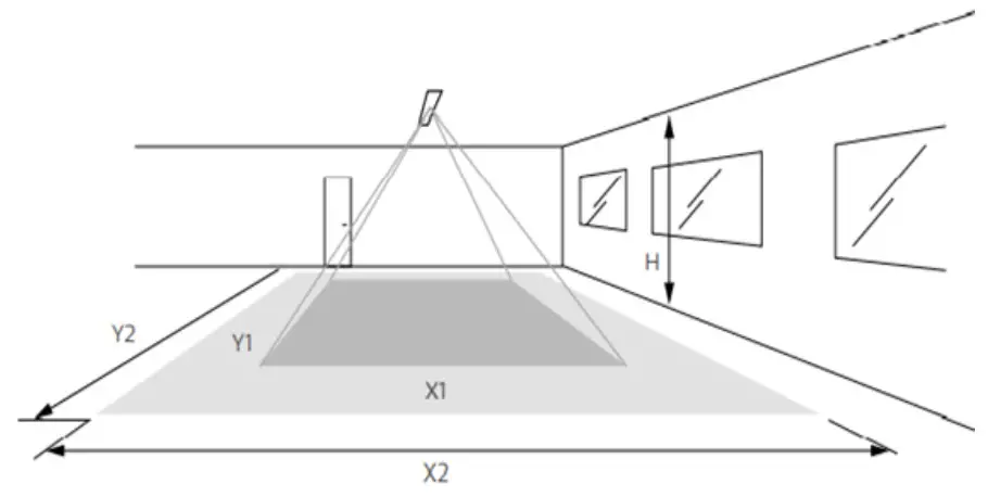
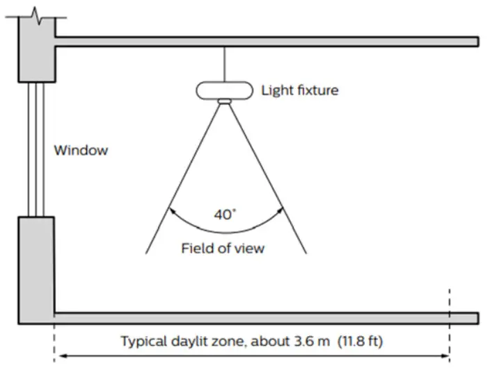
Daylight Sensor
The light sensor measures the total amount of light in a circular field of approximately 80% of the PIR detection area. The following aspects should be observed during installation:
- Minimum distance from the window = 2ft (0.6m).
- Prevent light reflections from outside entering the sensor (for example sunlight reflection on a car hood) as this will lead to incorrect light regulation.
As a guideline the formula 0.72 X H can be used to calculate the minimum distance between the window and sensor whereby H is the height from the bottom of the window to the sensor.
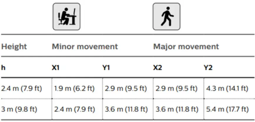
The detection area for the movement sensor can be roughly divided into two parts;
- Minor movements (person moving = 3ft
- Major movements (person moving = 3ft/s or 0.9m/s).
Photosensor spatial response
© 2019 Signify Holding. All rights are reserved.
Reproduction in whole or part is prohibited without the written consent of the copyright owner.
Phone: 604.888.6811
Web: ledalite.com/products Revision C
Signify North America Corporation. 400 Crossing Blvd, Suite 600 Bridgewater, NJ 08807.
Telephone: 855-486-2216
Signify Canada Ltd. 281 Hillmount Road, Markham, ON, Canada L6C 2S3.
Telephone: 800-668-9008![]()


