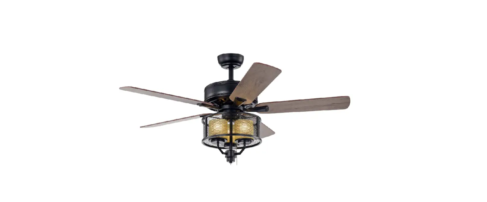
HM-GY5205AC
52-INCH DEROCATE CEILING FAN
USE AND CARE GUIDE
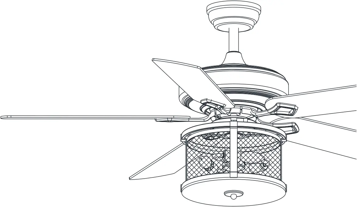
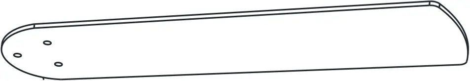
Ceiling fan
Safety Information
- To reduce the risk of electric shock, the electricity has been turned off at the circuit breaker or fuse box before begin.
- All wiring must be in accordance with the National Electrical Code NASI/NEPA 70-1999 and local electrical codes.Electrical installation should be performed by a qualified licensed electrician.
- The outlet box and support structure must be securely mounted and capable of reliably supporting 35lbs. (15.9kg). Use only UL listed outlet boxes marked “Acceptable for Fan Support of 35lbs(15.9kg) or less.”
- The fan must be mounted with a minimum of 7 ft. (2m) clearance from the trailing edge of the blades to the floor.
- Do not operate the reversing switch while the fan blades are in motion. You must turn the fan off and stop the blades before you reverse the blade direction.
- Do not place objects in the path of the blades.
- To avoid personal injury or damage to the fan and other items, please be careful when working around or cleaning the fan.
- Electrical diagrams are for reference only. Light kits that are not packed with the fan must be UL -listed and marked suitable for use with the model fan you are installing.Switches must be UL General Use Switches. Refer to the instructions packaged with the light kits and switches for proper assembly.
- After making electrical connections, spliced conductors should be turned upward and pushed carefully up into the outlet box.The wires should be spread apart with the grounded conductor and the equipment-grounding conductor on one side of the outlet box.
- All set screws must be checked and retightened where necessary before installation.
![]() WARNING
WARNING
To reduce the risk of personal injury, do not bend the blade brackets (also referred to as flanges) during assembly or after installation. Do not insert objects in the path of the blades.
Remove the rubber motor stops on the bottom of the fan before installing the blades or testing the motor.
To reduce the risk of fire or electric shock, do not use this fan with any solid-state speed control device.
To avoid possible electric shock, turn the electricity off at the main fuse box before wiring. If you feel you do not have enough electrical wiring knowledge or experience , contact a licensed electrician.
Electrical diagrams are for reference only. Optional use of any light kit shall be UL-listed and marked suitable for use with this fan.
To reduce the risk of fire, electric shock, or personal injury, mount to outlet box marked” Acceptable for fan support of 35 lbs. (15.9 kg) or less” and use the screws provided with the outlet box.
SPECIFICATION
Size | Speed | Volts | Amps | Watts | RPM | CFM | Net Weight | Gross Weight | Cube Feet |
| 52 in | Low | 120 | 0.22 | 12.5 | 66 | 1731 | Printed on the outer box | ||
Medium | 0.36 | 30.4 | 110 | 3356 | |||||
| High | 0.49 | 58.3 | 170 | 5043 | |||||
The above data are for reference only, Actually the motor speed of each ceiling fan is a little different. Any products, Subject to actual products as standard.
NOTE | These are approximate measures.They do not include the amps and wattage used by the light kit. |
Specifications & measurements shown are subject to± 5% variations.
TOOLS REQUIRED
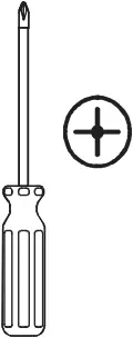 | 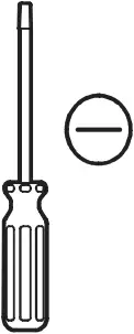 |  |  | |
| Phillips screwdriver | Flat blade screwdriver | Step ladder | Wire stripper | Electrical tape |
HARDWARE INCLUDED
components table
AA | Expansion bolts ×2 | Plastic wire nut (not to scale) ×3 |  DD DDBlade attachment screw ×16 |
Paper Washers ×16 | blade arm screw and lock washer ×1 | Balance sheet ×2 | Balance the clip ×1 |
NOTE | Hardware not shown to actual size. |
Pre-Installation(continued)
PACKAGE CONTENTS
 |  | ||||
| R-T | remote control(transmitter) | 1 | R-R | remote control(receiver) | 1 |
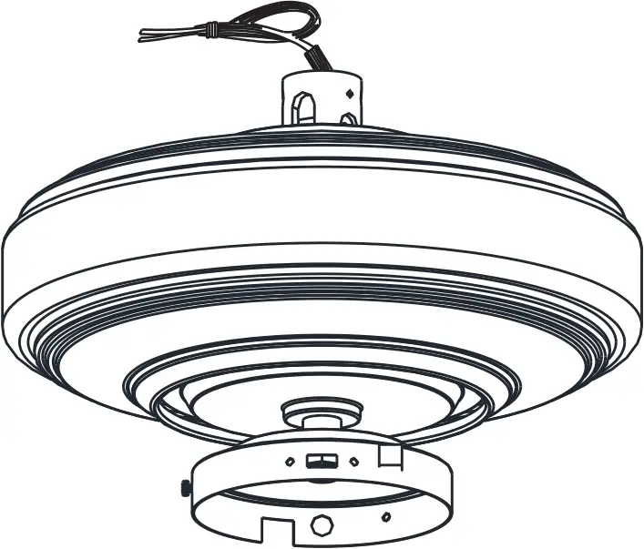
| A
Fan-Motor assembly ×1PCS | B
Arm(with per- installed screws) ×5PCS | C
Light kit fitter assembly ×1PCS |
| D
Blade X 5PCS | Glass ×1PCS J | |
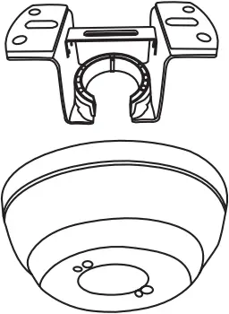
| E Slide – on mounting bracket
F Canopy X 1PCS | G 4.92 inch Ball/downrod assembly X 1PCS
H 9.84 inch Ball/downrod assembly X 1PCS | 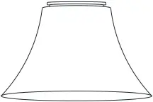 I Coupling cover X 1PCS |
Pls check whether above accessories are completed or not?Yes, and install.
Installation of the hanging bracket
(suspension part)(page-1)
Mounting screws ×4 | Expansion bolts ×2 |
- Mounting Bracket Washers
- Self tapping screw
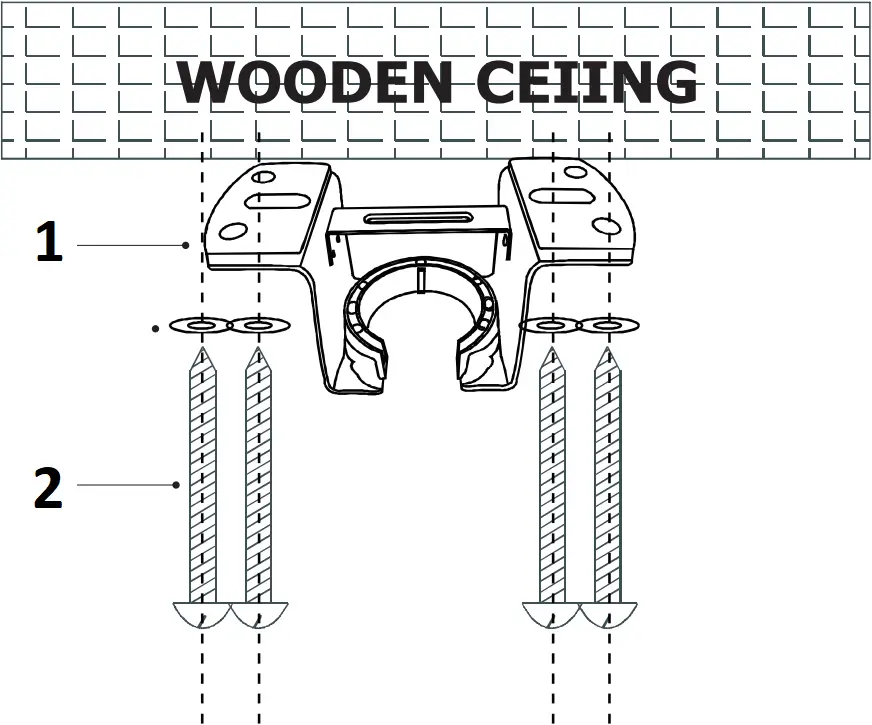
For wooden ceiling, use wood screw to drill on the wooden beam or the “junction box” to fix the hanging bracket(selection is made according to actual requirements of the customers)
STEP 1 A-WOODEN CEILING
SWITCH OFF THE ELECTRICAL MAINS AT THE CIRCUIT BREAKER FUSE BOX.
1) Use the Mounting Bracket (A) as a guide, mark the spots where the 4 Self Tapping Screws (B) will be drilled.
2) Remove the Mounting Bracket (A), drill 4 holes for 3MM diameter, install the mounting bracket onto wooden ceillng with the 4Self Tapping Screws (B)&Washers(C)
![]() IMPORTANT : SCREWS MUST BE TIGHTENED TILL SNUG
IMPORTANT : SCREWS MUST BE TIGHTENED TILL SNUG
NOTE | According to the ceiling of different materials, use different screws to fix the hanging bracket.Don’t fix the hanging bracket on the wood ceiling less than 12MM to prevent danger caused by loosening of screws. After the hanging bracket is completed, ensure that it can withstand the tension test of more than 68KG for safety. |
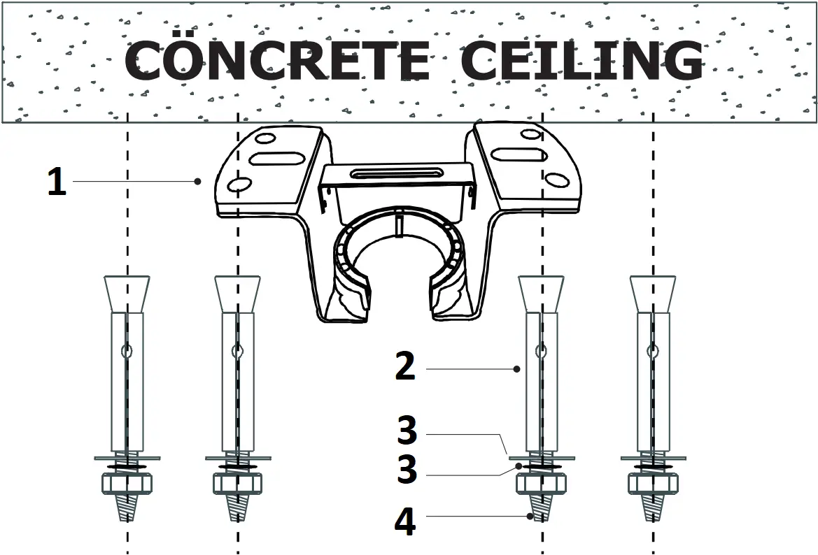
- Mounting Bracket
- Expansion Bolts
- Flat Washers
- Nuts
For concrete ceiling, use the percussion bit with diameter 8mm to drill holes according to the length of expansion screws. Then use the attached expansion screws to fix the hanging bracket onto the ceiling (selection is made according to actual requirements of the customers).
STEP 2 A-CONCRETE CEILING
SWITCH OFF THE ELECTRICAL MAINS AT THE CIRCUIT BREAKER FUSE BOX.
1 )Use the Mounting Bracket (A) as a guide, mark the spots where the 4 Expansion Bolts (B)will be drilled.
2 )Remove the Mounting Bracket (A), drill 4 holes and insert 4 Expansion Bolts (B)into the concrete ceiling, install the mounting bracket and secure with Flat Washers (C), Spring Washers (D) and Nuts (E).
![]() IMPORTANT : SCREWS & NUTS MUST BE TIGHTENED TILL SNUG
IMPORTANT : SCREWS & NUTS MUST BE TIGHTENED TILL SNUG
Electrical Outlet Box
![]() WARNING : Contact a qualified electrician to replace the outlet box if it is not suitable for ceiling cans
WARNING : Contact a qualified electrician to replace the outlet box if it is not suitable for ceiling cans
- If there is an existing outlet box,ensure it is clearly marked “Suitable for Fan Support”. if not, it must be replaced with an approve one.
- Secure the outlet box (or make sure the existing box is secured) directly to the building structure. Use appropriate fasteners and building materials.wood joist and outlet box must be able to support a minimum of 50 pounds.
- Fig.1,2 and 3 are examples of different ways to mount the outlet box in different situations.A hanger support bar may be required.
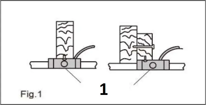
- Outlet Box
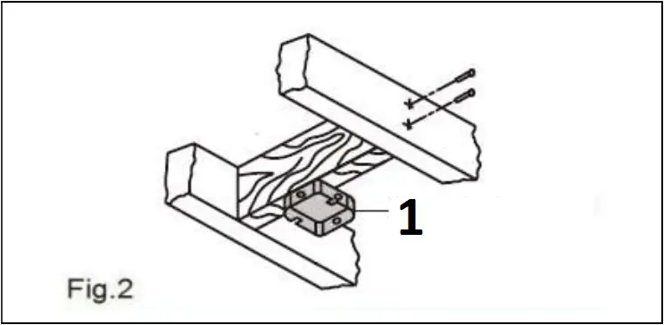
- Outlet Box
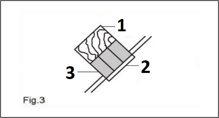
- Provide Strong Support
- Ceiling Mounting Plate
- Recessed Outlet Box
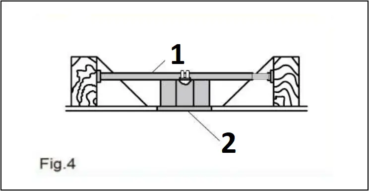
- Hanger Bar (not included)
- Outlet Box
Assembly – Hanging the Fan
| E Slide – on mounting bracket
F Canopy X 1PCS | G 4.92 inch Ball/downrod assembly X 1PCS
H 9.84 inch Ball/downrod assembly X 1PCS | I Coupling cover X 1PCS | A
Fan-Motor assembly ×1PCS |
Install downrod assembly
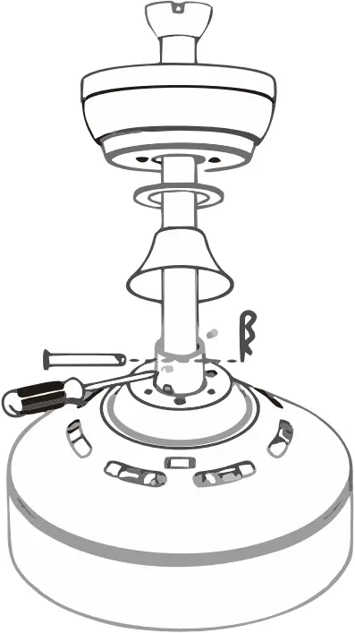
- Carefully feed the motor wires up though the downrod
- Align the holes and replace hanger pin and locking pin.
- Tighten the two colar setscrews.
- Slip coupling cover, canopy cover and canopy onto the downrod.
Hang the fan
- Lift the fan motor assembly up to the mounting bracket and seat the hanger ball in the mounting bracket socket.Rotate the fan motor assembly until the check groove drops into the registration slot and seats firmly. The downrod should not rotate if the is done correctly
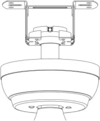
Install canopy
- Ensure the loosened screws is inserted into the key holes on the mounting bracket.
- Carefully raise the canopy up to the mounting bracket. Rotate the canopy clockwise.
- Secure the canopy by replacing the screws previously removed and tightening the screw previously loosened
- Place the canopy cover (if applicable)and rotate the canopy cover clockwise until it locks into position.
Fastening the blade arms to the motor
| DD Blade attachment screw ×16 | Paper Washers ×16 |
| B
Arm×5 | D
Blade X 5PCS |
Phillips screwdriver
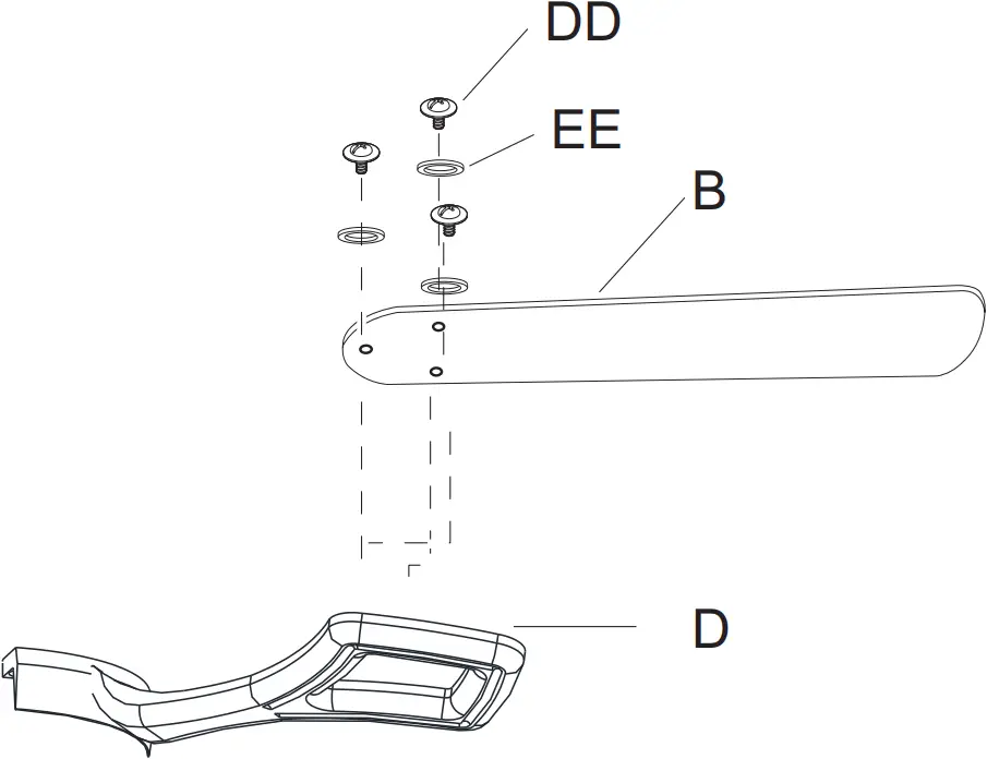
- Remove the pre installed screws
- Install the fan blade on the corresponding screw hole, and then install and fix it with the removed screws.
blade arm screw and lock washer ×10PCS (unscrew form motor) |
Phillips screwdriver
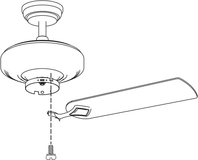
- Fasten the arm to the fan-motor assembly by inserting the alignment post int the slot on the bottom of the motor and tightening the pre-installed armscews.
- Repeat this step for the remaining blade assemblies.
 Finish |
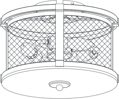
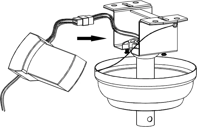
Assembly-Attaching the Lights
| C
Light kit fitter assembly ×1 |
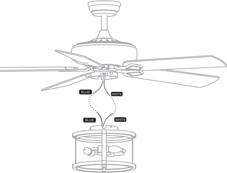
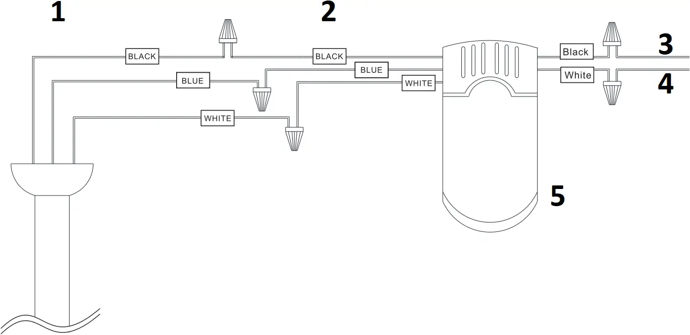
Motor kit Light kit
White ![]()
![]() White
White
Blue ![]()
![]() Blue
Blue
- Insert the “white” line in the switching box of the motor into the “white” line of the light and tie insulated rubber tape.
- Insert the “blue” line in the switching box of the motor into the “blue” line of the light and tie insulated rubber tape.
×3PCS (unscrew form motor) |
 Glass ×1PCS J |
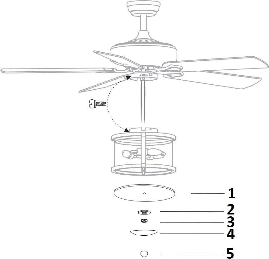
- Glass
- plastic spacer
- Nut
- Metal cover
- Metal Blall
Phillips screwdriver
- Take the wire into the switching box of the motor.
- Align the opening of switching box of the light at switch locking position of the positive and negative rotation of the motors withching box.
Place the cover screw in the screw of the switching box. - Insert the glass wafer into the luminaire
- Put in the plastic spacer
- Tighten with a nut, then close the metal cover, and tighten with a ball
Install the hanging part of the ceiling fan
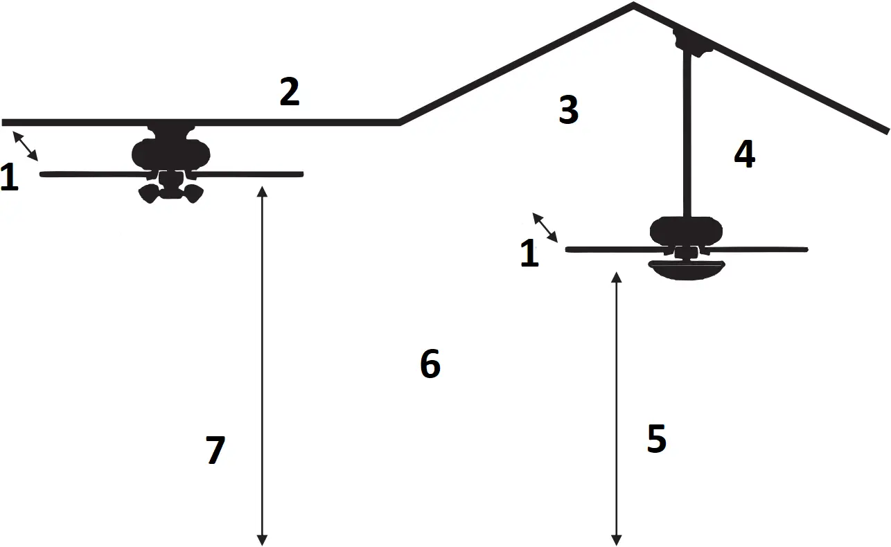
- blade tips should be as least 15cm from the nearest obstacle in any direction,eg tie bar,wall or roof beam
- A flush mount ceiling fan can only be mounted on a flat ceiling
- Different rod lengths are available for most fans
- Drop mounted fans can be mounted on a sloping ceiling up to 35degress in angle
- Ceiling fans blade should a minimum of 229cm and a maximum of 290cm above the floor to be safe and effective
- To convert a flush mount fan to a drop mount fan you will need a conversion kit
- Ceiling fans blade should be at least 229cm from the floor
Making the electrical connections
![]() WARNING:Each wire not supplied with this fan is designed to accept up to one12-gauge house wire and two wires from the fan.If you have large than 12-gauge house wiring or more than one house wire to connect to the fan wiring, consult an electrician for the proper size wire nuts to use.
WARNING:Each wire not supplied with this fan is designed to accept up to one12-gauge house wire and two wires from the fan.If you have large than 12-gauge house wiring or more than one house wire to connect to the fan wiring, consult an electrician for the proper size wire nuts to use.
![]() IMPORTANT: Use the plastic wire connectors(BB) supplied with your fan.Secure the connectors with electrical tape and ensure there are no loose strands or connections.
IMPORTANT: Use the plastic wire connectors(BB) supplied with your fan.Secure the connectors with electrical tape and ensure there are no loose strands or connections.
![]() WARNING:Remove the rubber motor stops on the bottom of fan before installing the blades or testing the motor.
WARNING:Remove the rubber motor stops on the bottom of fan before installing the blades or testing the motor.
![]() WARNING :Each wire not supplied with this fan is designed to accept up to one12-gauge house wire and two wires from the fan. If you have larger than12-gauge house wiring or more than one house wire to connect to the fan wiring, consult an electrician for the proper size wire nuts to use.
WARNING :Each wire not supplied with this fan is designed to accept up to one12-gauge house wire and two wires from the fan. If you have larger than12-gauge house wiring or more than one house wire to connect to the fan wiring, consult an electrician for the proper size wire nuts to use.
![]() WARNING: Remove the rubber motor stops on the bottom of the fan before installing the blades or testing the motor.
WARNING: Remove the rubber motor stops on the bottom of the fan before installing the blades or testing the motor.
![]() IMPORTANT: Use the plastic wire connectors(BB) supplied with your fan. Secure the connectors with electrical tape and ensure there are no loose strands or connections.
IMPORTANT: Use the plastic wire connectors(BB) supplied with your fan. Secure the connectors with electrical tape and ensure there are no loose strands or connections.
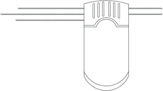
remote control(transmitter) X 1PCS R-T | R-R remote control(receiver) X 1PCS |
- From CEILING FAN
- From controller
- FOR AC IN L
- FOR AC IN N
- remote control <ONLY>
SWITCH OFF THE ELECTRICAL MAINS AT THE CIRCUIT BREAKER FUSE BOX
1 )Connect wires from receiver to terminal block properly as instruction diagram
Assembly – Hanging the Fan(continued)
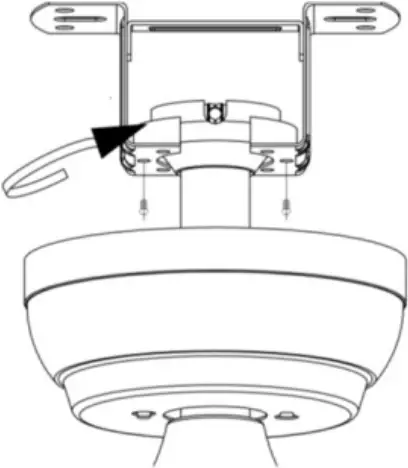
Preparing for mounting
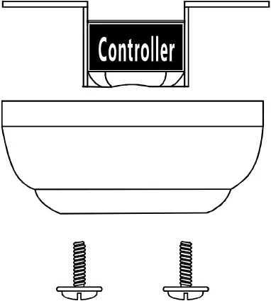
Install remote control
- Carefully push the canopy to the bottom of the mounting bracket, make two sliding holes aligned to the two prominent screws on the mounting bracket, and then turn clockwise until tight.
- Push the canopy ring to the bottom oft he canopy, slide the inner holes aligned to the two prominent screws on the mounting bracket again, and turn the canopy ring clockwise until tight.
Preparing for mounting
1:Remove the mounting bracket from the canopy by loosening the two canopy screws located in the L shaped slots
2:Remove and save the two canopy screws in the round holes. This will enable you to remove the mounting bracket
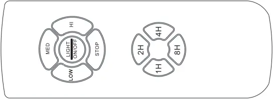
Use of remote control
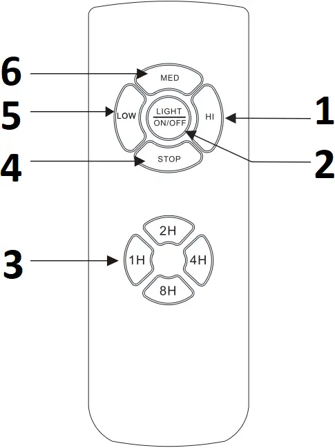
- Hi Level
- LIGHT ON/OFF
- Auto off after 1hr~8hr
- Fan On/Off
- Low Level
- Med Level
![]() FanSpeed Low Level
FanSpeed Low Level![]() FanSpeed Middle Level
FanSpeed Middle Level![]() FanSpeed High level
FanSpeed High level![]() FanSTOP
FanSTOP
![]() LIGHT NO/OFF
LIGHT NO/OFF
![]() Auto off after 1hr
Auto off after 1hr![]() Auto off after 2hr
Auto off after 2hr![]() Auto off after 4hr
Auto off after 4hr![]() Auto off after 8hr
Auto off after 8hr
Troubleshooting
Problem | Solution |
| The fan will not start |
|
| |
| The fan wobbles. |
|


