blizzard UVONIX Blackstar 120W UV LED Blacklight + Barndoors
Blizzard Lighting, LLC
http://www.blizzardpro.com
Waukesha, WI USA
Copyright (c) 2021
GETTING STARTED
What’s In The Box?
- UVonix™ Blackstar
- PowerCON-Compatible Power Cord
- Mounting Brackets and Locking Knobs
- Barndoor Attachment
- This Lovely User Manual
Getting It Out Of the Box
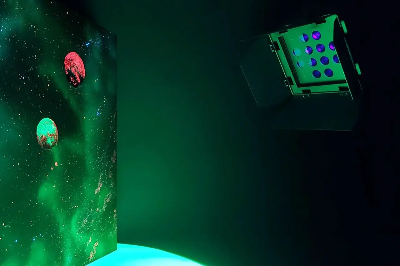
Congratulations on your purchase of the UVonix™ Blackstar, high-output 365nm ultraviolet LED black light fixture. Now that you’ve got your Blackstar, you should carefully unpack the box and check the contents to ensure that all parts are present and in good condition. If anything looks as if it has been damaged in transit, notify the shipper immediately and keep the packing material for inspection. Again, please save the carton and all packing materials. If a fixture must be returned to the factory, it is important that the fixture be returned in he original factory box and packing.
Powering Up!
All fixtures must be powered directly off a switched circuit and cannot be run off a rheostat (variable resistor) or dimmer circuit, even if the rheostat or dimmer channel is used solely for a 0% to 100% switch.
Warning! All fixtures must be connected to circuits with a suitable Ground (Earthing).
Getting A Hold Of Us
If something happens to go wrong, visit blizzardpro.com/support and ,open a support ticket. We’ll be happy to help, honest.
Disclaimer: The information and specifications contained in this document are subject to change without notice. Blizzard Lighting™ assumes no responsibility or liability for any errors or omissions that may appear in this user manual.
Blizzard Lighting™ reserves the right to update the existing document or to create a new document to correct any errors or omissions at any time. You can download the latest version of this document from www.blizzardpro.com.
| Author: | Date: | Last Edited: | Date: |
| J. Thomas | 2/4/2021 | J. Thomas | 5/27/2021 |
Safety Instructions
WARNING: Please read these instructions carefully. They include important information about the installation, usage and maintenance of this product.
- Please keep this User Guide for future use. If you sell the unit to someone else, be sure that they also receive this User Guide.
- ALWAYS make sure that you are connecting to the proper voltage, and that the line voltage you are connecting to is not higher than that stated on the decal or rear panel of the fixture.
- This product is intended for indoor use only.
- To prevent risk of fire or shock, do not expose fixture to rain or moisture.
- Make sure there are no flammable materials close to the unit while operating.
- The unit must be installed in a location with adequate ventilation, at least 20in (50cm) from adjacent surfaces. Be sure that no ventilation slots are blocked.
- ALWAYS disconnect from the power source before servicing or replacing fuse and be sure to replace with same fuse size and type.
- ALWAYS secure fixture using a safety chain. NEVER carry the fixture by its head. Use its carrying handles.
- DO NOT operate at ambient temperatures higher than 104°F (40°C).
- In the event of a serious operating problem, stop using the unit immediately. NEVER try to repair the unit by yourself. Repairs carried out by unskilled people can lead to damage or malfunction. Please contact the nearest authorized technical assistance center. Always use the same type spare parts.
- NEVER connect the device to a dimmer pack.
- Make sure the power cord is never crimped or damaged.
- Never disconnect the power cord by pulling or tugging on the cord.
- Avoid direct eye exposure to the light source while it is on.
Caution! There are no user serviceable parts inside the unit. Do not open the housing or attempt any repairs yourself. In the unlikely event your unit may require service, please open a support ticket at www.blizzardpro.com/support
MEET THE UVONIX™ BLACKSTAR
Main Features
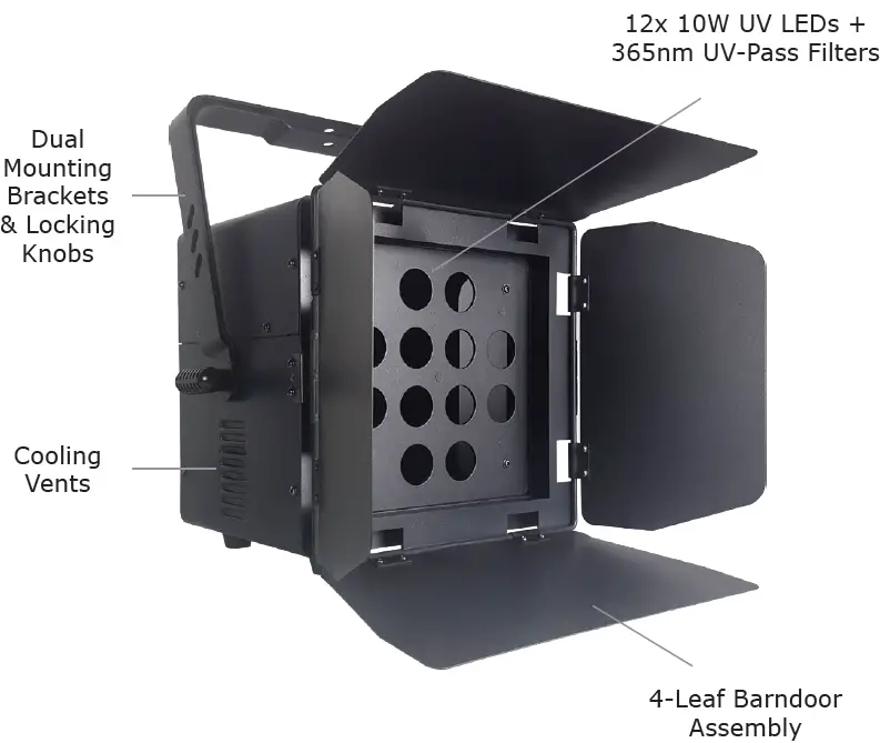
- 12x 10W UV LEDs, 50,000+ hour lifetime
- UV-pass lens filters for pure 365nm wavelength
- 30° beam angle
- Electronic dimming & strobe effects
- Flicker-free resolution, perfect for video
- 4 user-selectable dimming curves
- 6 dimming delay settings (5/10/15/20/25/30ms)
- Adjustable LED refresh rates (900Hz-25KHz)
- Barndoor attachment for light shaping
- Dual mounting brackets for flexible positioning
- 3/5-pin male/female XLR input & output connections
- PowerCON-compatible input/output connections
Control
- Protocol: USITT DMX-512
- DMX channels: 1/2/4-channels
- Easy-to-use 4-button control panel with LCD display
- Operating modes: DMX-512, M/S, and Standalone
DMX Quick Reference (1-Channel Mode)
| 1CH | What It Does |
| 1 | Dimmer |
DMX Quick Reference (2-Channel Modes)
| 2CH | What It Does |
| 1 | Dimmer |
| 2 | Dimmer (fine 16-bit) |
DMX Quick Reference (4-Channel Modes)
| 4CH | What It Does |
| 1 | Strobe Effects |
| 2 | Dimmer |
| 3 | Dimmer (fine 16-bit) |
| 4 | 32-Bit Dimming Curves |
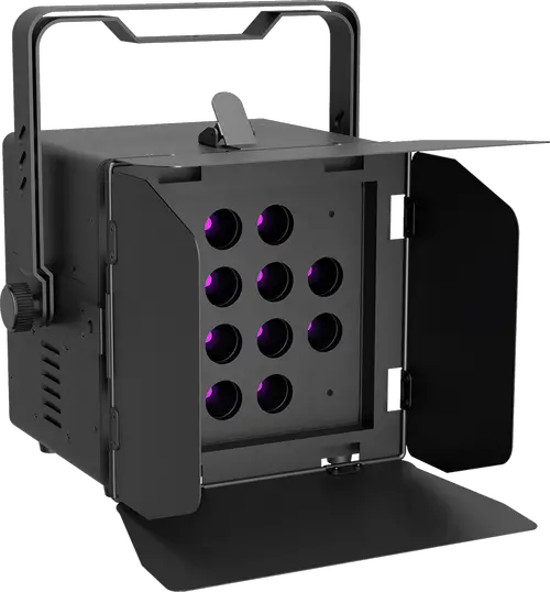
UVonix™ Blackstar Pin-Up Picture
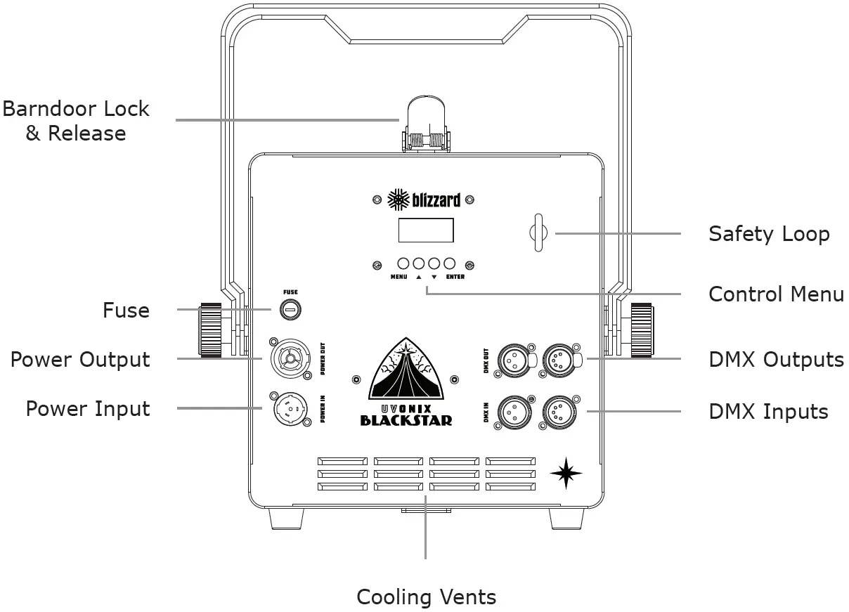
The Rear Connections
SETUP
WARNING: Before replacing the fuse, disconnect the power cord. ALWAYS replace it with the same type and rating.
Fuse Replacement
Remove the fuse holder from of its housing. Then take out the damaged fuse from its holder and replace with exact same type of fuse. Reattach the fuse holder, and then reconnect power.
The fuse in this unit is a fast-acting, low breaking capacity 5X20mm glass fuse with a rating of 3.15A, 250V.
Connecting A Bunch of UVonix™ Blackstars
You will need a serial data link to run light shows using a DMX-512 controller or to run shows on two or more fixtures set to sync in master/slave operating mode. The combined number of channels required by all the fixtures on a serial data link determines the number of fixtures the data link can support.
Fixtures on a serial data link must be daisy chained in one single line. Also, connecting more than 32 fixtures on one serial data link without the use of a DMX optically-isolated splitter may result in deterioration of the digital DMX signal. The maximum recommended cable-run distance is 500 meters (1640 ft). The maximum recommended number of fixtures on a serial data link is 32 fixtures.
Data/DMX Cabling
To link fixtures together you’ll need data cables. You should use data-grade cables that can carry a high quality signal and are less prone to electromagnetic interference.
For instance, Belden© 9841 meets the specifications for EIA RS-485 applications. Standard microphone cables will “probably” be OK, but note that they cannot transmit DMX data as reliably over long distances. The cable should have the following characteristics:
- 2-conductor twisted pair plus a shield
- Maximum capacitance between conductors – 30 pF/ft.
- Maximum capacitance between conductor & shield – 55 pF/ft.
- Maximum resistance of 20 ohms / 1000 ft.
- Nominal impedance 100 – 140 ohms
Cable Connectors
Cables must have a male XLR connector on one end and a female XLR connec-tor on the other end. (Duh!)
A Word on Termination:
DMX is a resilient communication protocol, however errors still occasionally occur. Termination reduces signal errors, and therefore best practices include use of a terminator in all circumstances. If you are experiencing problems with erratic fixture behavior, especially over long signal cable runs, a terminator may help improve performance.
To build your own DMX Terminator:
Obtain a 120-ohm, 1/4-watt resistor, and wire it between pins 2 & 3 of the last fixture. They are also readily available from specialty retailers.
CAUTION: Do not allow contact between the common and the fixture’s chassis ground. Grounding the common can cause a ground loop, and your fixture may perform erratically. Test cables with an ohm meter to verify correct polarity and to make sure the pins are not grounded or shorted to the shield or each other.
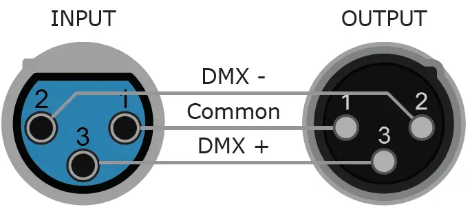
3-Pin??? 5-Pin??? Huh?!?
This fixture is equipped with both 3-pin and 5-pin XLR sockets for DMX input and output. The sockets are wired in parallel. Only use a shielded twisted pair cable designed for RS-485 and 3/5-pin XLR connectors to connect the controller to the fixture, or the fixture to another fixture.
| Conductor | 3-Pin Female (Output) | 5-Pin Male (Input) |
| Ground/Shield | Pin 1 | Pin 1 |
| Data 1- (Primary Data Link) | Pin 2 | Pin 2 |
| Data 1+ (Primary Data Link) | Pin 3 | Pin 3 |
| Data 2- (Optional Secondary Data Link) | — | Pin 4 – Do Not Use |
| Data 2+ (Optional Secondary Data Link) | — | Pin 5 – Do Not Use |
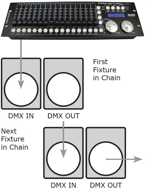
Take It To The Next Level: Setting Up DMX Control
Step 1: Connect the male connector of the DMX cable to the female connector (output) on the controller.
Step 2: Connect the female connector of the DMX cable to the first fixture’s male connector (input).
Note: It doesn’t matter which fixture address is the first one connected. We recommend connecting the fixtures in terms of their proximity to the controller, rather than connecting the lowest fixture number first, and so on.
Step 3: Connect other fixtures in the chain from output to input as above. Place a DMX terminator on the output of the final fixture to ensure best communication.
Fixture Linking (M/S Mode)
- Connect the male connector side of the DMX cable to the output female connector of the first fixture.

- Connect the end of the cable coming from the first fixture which will have a female connector to the input connector of the next fixture consisting of a male connector. Then, proceed to connect from the output as stated above to the input of the following fixture and so on.
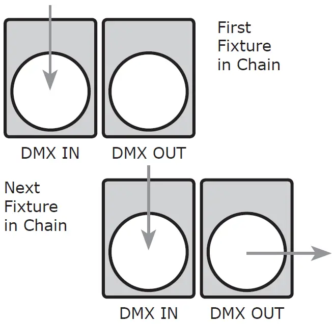
A quick note: Often, the setup for Master-Slave and Standalone operation requires that the first fixture in the chain be initialized for this purpose via either settings in the control panel or DIP-switches. Secondarily, the fixtures that follow may also require a slave setting.
Check the “Operating Adjustments” section in this manual for complete instructions for this type of setup and configuration.
Mounting & Rigging
This fixture may be mounted in any SAFE position provided there is enough room for ventilation. The fan or vent pathway must never be obstructed.
IMPORTANT: Regardless of the rigging option you choose for your fixtures, always be sure to secure your fixture with a safety cable.
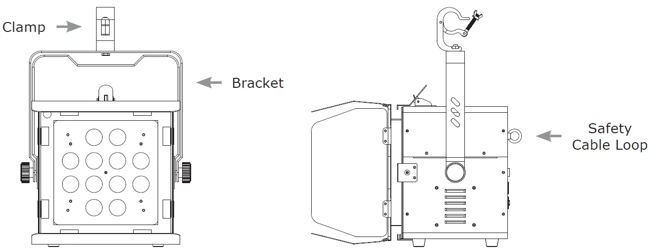
Mount the fixture using a suitable “C” or “O” type clamp. The clamp should be rated to hold at least 10x the fixture’s weight to ensure structural stability. Do not mount to surfaces of unknown strength, and ensure properly rated rigging is used when mounting fixtures overhead.
Overhead mounting requires extensive experience, which includes calculating working load limits, knowledge of the installation material being used, and periodic safety inspections. If you lack these qualifications, do not attempt the installation yourself.
OPERATING ADJUSTMENTS
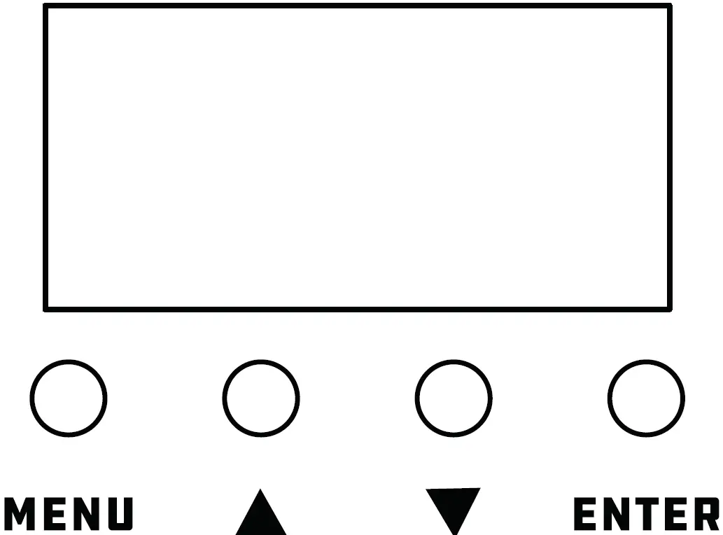
The Control Panel
All the features and different modes possible with the UVonix™ Blackstar are accessed by using the control panel on the rear of the fixture. There are 4 control buttons under to the LCD display which allow you to navigate through the various control panel menus.
<MENU> Is used to navigate to the previous higher-level menu item.
<UP> Scrolls through menu items and numbers in ascending order.
<DOWN> Scrolls through menu items and numbers in descending order.
<ENTER> Is used to select and confirm/store the current selection.
The control panel LED display shows the menu items you select from the menu map on page #11. When a menu function is selected, the display will show im-mediately the first available option for the selected menu function. To select a menu item, press <ENTER>.
Use the <UP> and <DOWN> buttons to navigate the menu options. Press the <ENTER> button to select the menu function currently displayed, or to enable a menu option. To return to the previous option or menu without changing the value, press the <MENU> button.
| DMX Address | Address | Set the starting address (001-512) | |
| Operate Mode | Mode DMX-CH | 1CH | |
| 2CH | |||
| 4CH | |||
| Mode Ma./Sa. | Slave | ||
| Master | |||
| Mode LostDMX | Blackout Hold | ||
| Mode Manual | Dimmer (0% <–> 100%) | ||
| Strobe | |||
| 000 <-> 015 016 <-> 075 076 <-> 135 136 <-> 195 196 <-> 215 216 <-> 235 236 <-> 255 | No function Strobe Pulse effect Random strobe Gradual effect 1 Gradual effect 2 Gradual effect 3 | ||
| System Setting | Sys.Set DimCurve | Linear | |
| Log | |||
| Exp | |||
| S-Curve | |||
| Sys.Set DimFreq. | PWM frequency: | 1500Hz | |
| 900Hz | 2500Hz | ||
| 1000Hz | 4000Hz | ||
| 1100Hz | 10KHz | ||
| 1200Hz | 15KHz | ||
| 1300Hz | 20KHz | ||
| 1400Hz | 25KHz | ||
| Sys.Set DimDelay | Dimming delay: | 15ms | |
| OFF | 20ms | ||
| 5ms | 25ms | ||
| 10ms | 30ms | ||
| Sys.Set Display | Bk.Light (LCD Backlight) | On (constant on) | |
| Off | |||
| Sys.Set Default | Default | No | |
| Yes (factory reset) | |||
| Status Info | Sys.Info Firmware | Firmware version | |
| Sys.Info Op. Hours | Total hours in use | ||
| Sys.Info Temp | Led.Temp (xxxC) | ||
| Led.Temp (xxxF) | |||
| Sys.Info Fan | Fan.Volt (xxxV) | ||
| Fan.RPM (A:xxx) | |||
| Fan.RPM (B:xxx) | |||
Starting DMX Address
- Navigate the menu to reach DMX Address, and press <ENTER>.
- Use the <UP/DOWN> buttons to select a value from 001-512, and press <ENTER> to confirm.
DMX Channel Mode
- Navigate the menu to reach Operate Mode, and press <ENTER>.
- Use the <UP/DOWN> buttons to select DMX-CH. Press <ENTER>.
- Use the <UP/DOWN> buttons to select CH1, CH2, or CH4, and press <ENTER> to confirm.
M/S Mode
- Navigate the menu to reach Operate Mode, and press <ENTER>.
- Use the <UP/DOWN> buttons to select Ma./Sa. Press <ENTER>.
- Use the <UP/DOWN> buttons to select Master or Slave, and press <ENTER> to confirm.
Lost DMX Signal
- Navigate the menu to reach Operate Mode, and press <ENTER>.
- Use the <UP/DOWN> buttons to select LostDMX. Press <ENTER>.
- Use the <UP/DOWN> buttons to select Blackout or Hold, and press <ENTER> to confirm.
Manual Mode
- Navigate the menu to reach Operate Mode, and press <ENTER>.
- Use the <UP/DOWN> buttons to select Manual. Press <ENTER>.
- The Dimmer values will increase/decrease the brightness from 0% to 100%, and Strobe values will change the effect (see strobe DMX values).
Dimming Curves
- Navigate the menu to reach System Setting, and press <ENTER>.
- Use the <UP/DOWN> buttons to select DimCurve. Press <ENTER>.
- Use the <UP/DOWN> buttons to select Linear, Log, Exp, or S-Curve, and press <ENTER>.
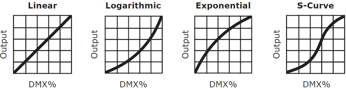
Note: Smoother (and slower) dimming capabilities can be achieved with use of the 4 available dimming curve settings.
Dimming Frequency
- Navigate the menu to reach System Setting, and press <ENTER>.
- Use the <UP/DOWN> buttons to select DimFreq. Press <ENTER>.
- Use the <UP/DOWN> buttons to select a dimming frequency ranging from 900Hz-25KHz, and press <ENTER> to confirm.
Dimming Delay
- Navigate the menu to reach System Setting, and press <ENTER>.
- Use the <UP/DOWN> buttons to select DimDelay. Press <ENTER>.
- Use the <UP/DOWN> buttons to select any dimming delay option up to 30Ms, and press <ENTER> to confirm.
System Reset
- Navigate the menu to reach System Setting, and press <ENTER>.
- Use the <UP/DOWN> buttons to select Default. Press <ENTER>.
- Use the <UP/DOWN> buttons to select Yes (factory reset) or No, and press <ENTER> to confirm.
DMX Values In-Depth (1-Channel Mode)
| 1CH | Value | What It Does |
| 1 | 000 <-> 255 | Dimmer (0% <–> 100%) |
DMX Values In-Depth (2-Channel Mode)
| 2CH | Value | What It Does |
| 1 | 000 <-> 255 | Dimmer (0% <–> 100%) |
| 2 | 000 <-> 255 | Fine dimmer (0% <–> 100%) |
DMX Values In-Depth (4-Channel Mode)
| 4CH | Value | What It Does |
| 1 | 000 <-> 015 016 <-> 075 076 <-> 135 136 <-> 195 196 <-> 215 216 <-> 235 236 <-> 255 | Strobe No Function Strobe (slow <-> fast) Pulse effect (slow <-> fast) Random strobe (slow <-> fast) Gradual effect 1 Gradual effect 2 Gradual effect 3 |
| 2 | 000 <-> 255 | Dimmer (0% <–> 100%) |
| 3 | 000 <-> 255 | Fine dimmer (0% <–> 100%) |
| 4 | 000 <-> 005 006 <-> 063 064 <-> 127 128 <-> 191 192 <-> 255 | Dimming Curves No Function Linear Logarithmic Exponential S-Curve |
APPENDIX
Keeping Your UVonix™ Blackstar As Good As New
The fixture you’ve received is a rugged, tough piece of pro lighting equipment, and as long as you take care of it, it will take care of you. That said, you’ll need to take care of it if you want it to operate as designed. You should keep the fixture clean, especially if you are using it in an environment with a lot of dust, fog, haze, wild animals, wild teenagers or spilled drinks.
Cleaning the optics routinely with a suitable glass cleaner will greatly improve the quality of light output. Keeping the fans free of dust and debris will keep the fixture running cool and prevent damage from overheating.
In transit, keep the fixtures in cases. You wouldn’t throw a prized guitar, drumset, or other piece of expensive gear into a gear trailer without a case, and similarly, you shouldn’t even think about doing it with your shiny new light fixtures.
Common sense and taking care of your fixtures will be the single biggest thing you can do to keep them running at peak performance and let you worry about designing a great light show, putting on a great concert, or maximizing your client’s satisfaction and “wow factor.” That’s what it’s all about, after all!
Returns (Gasp!)
We’ve taken a lot of precautions to make sure you never even have to worry about sending a defective unit back, or sending a unit in for service. But,
like any complex piece of equipment designed and built by humans, once in a while, something doesn’t go as planned. If you find yourself with a fixture that isn’t behaving like a good little fixture should, you’ll need to obtain a Return Authorization (RA).
Don’t worry, this is easy. Just visit www.blizzardpro.com/support and open a support ticket, and we’ll issue you an RA. Then, you’ll need to send the unit to us using a trackable, pre-paid freight method. We suggest using USPS Priority or UPS. Make sure you carefully pack the fixture for transit, and whenever possible, use the original box & packing for shipping.
When returning your fixture for service, be sure to include the following:
- Your contact information (Name, Address, Phone Number, Email address).
- The RA# issued to you
- A brief description of the problem/symptoms.
We will, at our discretion, repair or replace the fixture. Please remember that any shipping damage which occurs in transit to us is the customer’s responsibility, so pack it well!
Shipping Issues
Damage incurred in shipping is the responsibility of the shipper, and must be reported to the carrier immediately upon receipt of the items. Claims must be made within seven (7) days of receipt.
Tech Specs!
| Weight & Dimensions | |
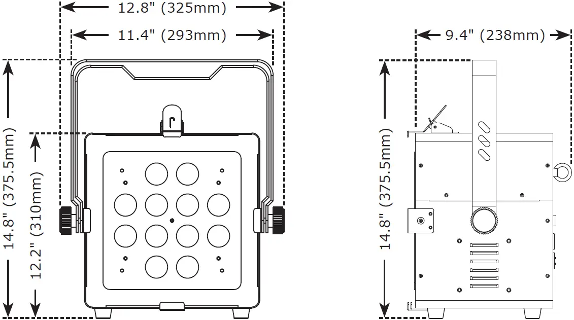
| Width | 12.8 inches (325mm) |
| Depth | 14.8 inches (375.5mm) |
| Height | 9.4 inches (238mm) |
| Weight | 20.7 lbs. (9.4 kg) |
| Power | |
| Operating Voltage | 100-240VAC, 50-60 Hz |
| Power Consumption | 155W, 1.42A, PF: .99 |
| Fuse | 3.15A 250V, 5X20mm |
| Light Source | |
| LED | 12* 10-watt UV LEDs |
| Optical | |
| Beam Angle | 30° beam angle |
| Wavelength | 365nm |
| Thermal | |
| Max. Operating Temp. | 104° F (40 degrees C) ambient |
| Control | |
| Protocol | USITT DMX-512 |
| DMX Channels | 1/2/4-channel |
| Input/Output | 3/5-pin XLR male/female |
| Other Operating Modes | DMX-512, M/S, and Standalone |
| Warranty | 2-year limited warranty, does not cover malfunction caused by damage to LEDs. |
Dimensional Drawings
Enjoy your product!
Our sincerest thanks for your purchase!
–The team @ Blizzard Lighting


