FLOTIDE SSCmini Salt Chlorinator User Manual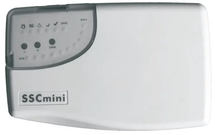
SAFETY WARNING AND RECOMMENDDATIONS
The equipment should be assembled and handled by truly qualified people.
Current electrical and accident prevention regulations should be followed.
Under no circumstances will the manufacturer be held responsible for the assembly, installation or start-up, nor any handling or fitting of components unless they are corded out on its premises. The working voltage of SSCminr is 220-240V, 50/60Hz. Do not attempt to alter the system to operate at a different voltage.
Check all the electrical connectors to avoid false contacts and their consequent overheating.
Before installing and replacing any component, disconnect the control unit from the main power supply; only replacements provided by Emaux can be used for replacing. The control unit must be installed in places with sufficient ventilation.
The equipment should not be installed working pressure exceeds 2.0 bor.
If the supply cord is damaged, it must be replaced by the manufacturer, its service agent or similarly qualified persons in order to avoid o hazard.
This appliance can not be used by children and persons with reduced physical, sensory or mental capabilities or lack of experience and knowledge. Children shall not ploy with the appliance.
Clearing and user maintenance shall not be mode by children without supervision.
SAFETY GUIDE
IMPORTANT: The instruction manual you are holding includes essential information on the safety measures to be implemented for installation and start-up. Therefore, the installer as well as the user must read the instructions before beginning installation and start-up.
Keep this manual for future reference.
When using this electrical equipment, basic safety measures listed below should be followed:
- Disconnect all AC power during installation.
- To reduce the risk of injury, do not permit children to use this product unless they are closely supervised.
- A green colored terminal marked “Earth Ground” is located inside the wiring compartment. To reduce the risk of electric shock, this terminal must be connected to the grounding means provided in the electric supply service panel with a continuous copper wire equivalent in size to the circuit conductors supplying the equipment.
- To reduce the risk of electric shock, conned the local common bonding grid in the area of the swimming pool or spa to these terminals with an insulated or bare copper conductor.
CONTENTS OF PACKAGE
Following components are contained in the package:
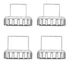
| SSCmini® Control unit | SSC mini Electrolytic Cell | 1.5″ and 2″ Universal Unions |
 |  |  |
| Standard working voltage | 220-240 V AC — 50/60 Hz | |
| Maximum chlorine production | 20 g/h | |
| Maximum Pool Volume | 90 m3 | |
| Water salinity required | 3-4 g/I | |
| Working Temperature of Water | 10°C — 45°C (50°F — 113°F) | |
| Electrodes | Titanium plates | |
INTRODUCTION
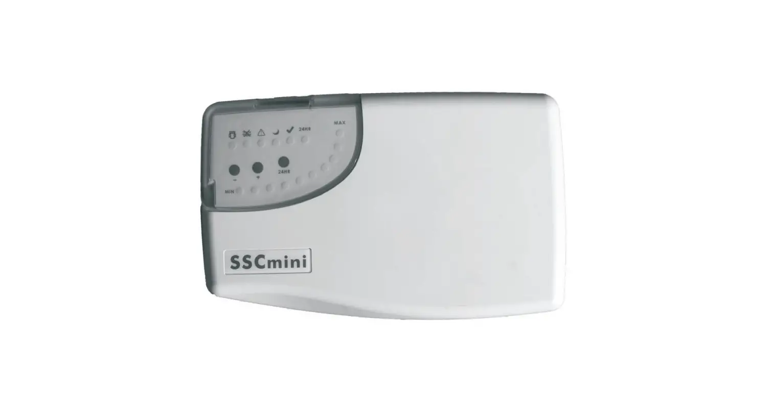
SSCminis is an automatic chlorine generation system for pool sanitization and it is composed by two main components: an electrolytic cell and a control unit.
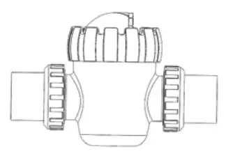
ELECTROLYTIC CELL
The electrolytic cell is composed by o number of titanium plates (electrodes) placed in o cell holder. The control unit regulates electrical current that posses through the titanium plates. One extreme of the plates will be anode and the other will be cathode. Adding a certain concentration of salt in the water, this posses through the plates and thonks to the electrical current, the Hypochlorous acid is produced.
The following chemical reactions are produced in the plates of the electrolytic cell:
Positive pole (anode):
Negative pole (cathode):
Final chemical reaction: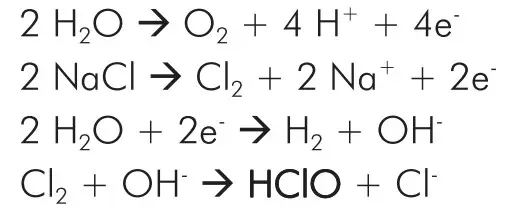
The operation requires a certain concentration of salt (4000 ppm), low enough that it normally will not be tasted. The SSCmini4 automatically sanitizes your pool by converting the salt into Hypochlorous acid which kills bacteria and algae in the pool through o process called electrolysis.
Because chlorine will revert back to sodium chloride after killing the bacteria, the above reactions will continuously recycle virtually eliminating the need to add sanitizing chemicals to your pool. The only time you may need to add more salt to the pool is when water is replenished due to backwashing, draining, or splashing.
CONTROL UNIT
The control unit is provided with a microprocessor driven control system to regulate operation time inform about .55Cmine operation status and errors. The system olso includes o self-cleaning procedure that ovoids scale formation on the electrodes.
WATER CHEMISTRY
The following table shows the recommended levels of the chemical parameters required for a proper quality of water in the pool by using SSCmini®. Test your water periodically and ensure the levels are within the recommended range.
- Salt Level: 3000 – 4000 ppm
- Free Chlorine: 1.0 — 3.0 ppm
- pH Value: 7.2 — 7.6
- Cyanuric Acid (stabilizer): 30 — 50 ppm
- Total Alkalinity: 80 — 120 ppm
- Calcium Hardness: 200 — 400 ppm
- Metal: 0 ppm
SALT LEVEL
The amount of salt required when using the SSCmini’ is between 3000 and 4000 ppm. To reach this concentration, it is necessary to 4 kg of salt per each cubic meter of pool water. Low salinity (below 2500ppm) will cause premoture cell failure. High salinity (above 6000ppm) will result in electro-oxidation and the corrosion of stainless steel swimming pool fixtures. Salt required according to the pool volume:
| Pool volume (m3) | Salt (kg) | Pool volume (Gallon) | Salt (Pound) |
| 10 | 40 | 2,642 | 88 |
| 20 | 80 | 5,283 | 176 |
| 30 | 120 | 7,925 | 264 |
| 40 | 160 | 10,567 | 352 |
| 50 | 200 | 13,209 | 440 |
| 60 | 240 | 15,850 | 528 |
| 70 | 280 | 18,492 | 616 |
| 80 | 320 | 21,134 | 704 |
| 90 | 360 | 23,775 | 792 |
Note: Table based on 4000 ppm of salt per m3 of water.
TYPE OF SALT
The most common salt used in swimming pools with Salt Electrolysis is Sodium Chlorine (NaCI) that is 99% pure. DO NOT use the following types of salts:
- rock salt;
- salt with more than 1% yellow prussiate of soda;
- Salt with more than 1% of anti-caking additives;
- Iodized salt.
ADDING AND REMOVING SALT
Before adding the salt into the pool, turn your filtration pump on and set your filtration valve manifold in position “Filtration”. Add the salt directly into the pool or balance tank and do not allow the salt to sit in a pile on the bottom of the pool. Keep the filtration system running for 24 hours using a main drain or a vacuum suction nozzle as a main suction line.
The only way to remove the salt in the pool water is to partially drain the pool and refill with fresh water.
INSTALLATION
CONTROL UNIT INSTALLATION
The SSOninrs’ control unit is contained in a rointight enclosure that is suitable for outdoor mounting (IPX4 rating). However, the following points must be token into consideration for a correct installation of the control unit:
- Install the Control Unit using the mounting template provided with the package. The unit should be installed in a minimum distance of 3 meters from the swimming pool, 1.5 meters from the ground, within 2 meters from electrical enclosure, and within 3 meters from where the cell will be installed.
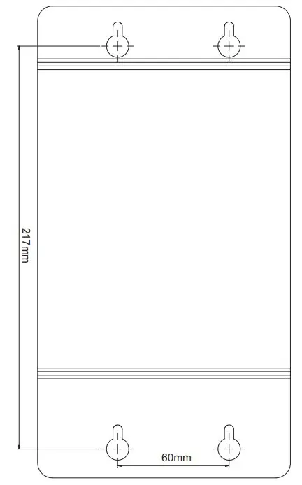
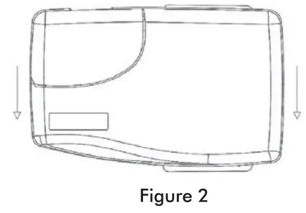
- Fix the mounting template on the wall and drill 4 holes with a diameter of 8mm in the wall according to the mounting template (Figure 1). Use expansion bolts to support the control unit.

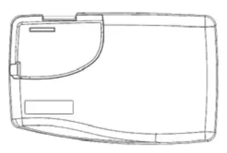
- Hong the control box on the fixed bolts (Figure 2) and make sure that the power cable and cell cable also reach the Control Unit.

- Don’t install the control unit under direct sun light.
- The control unit should be installed away from chemicals storage.
- The unit must be kept away from heat sources and any equipment which produce heat.
- Plug-in power supply into a suitable weatherproof outlet socket with circuit breaker.

ELECTROLYTIC CELL INSTALLATION
Please follow the recommendations below to install the electrolytic cell properly:
- The electrolytic cell should be mounted once the installation of all other swimming pool equipment is completed (filtration pump, filter, heating system).
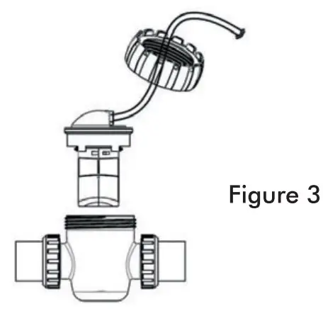
- The electrolytic cell is designed to install in PVC pool plumbing. The opening of the cell holder must be placed upright to enable the maintenance of titanium plates. To install the cell, cut off at least 187mm of pipe. Fix the electrolytic holder on the pipe, put the electrodes into the cell. Make the electrode cable go through the nut (Figure 3).

- Connect the unions to the pipe and make necessary adjustments for a proper connection. Once adjusted, fix the connection with PVC glue and tighten the union nuts.
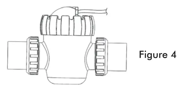
- Place the electrodes inside the holder and tighten the nut of the cell; connect the electrode cable to the control unit; tighten the nut to ensure the good contact (Figure 4).
Note: the cell con also be installed in a vertical position.
START_UP
Before starting the SSCmini” unit, the following points have to be taken into consideration:
- Check if the filter is completely clean, and ensure that the swimming pool and the installation do not contain any metals dissolved or algae.
- Ensure that the heating equipment (if any) is suitable for use in salt water.
- Ensure that chemical parameters of pool water are within the recommended range (see Chapter 6).
- Run your filtration system for 24 hours before starting salt chlorinator so that salt in the swimming pool is completely dissolved.
For stop-up, set the system at 50% of working time. It will take o few days of adjustments to find the most appropriate setting according to the chlorine demand of your swimming pool. Once determined, only minor adjustments might be necessary in cases of splashing, bockwoshing, rain, etc.
The temperature of the water is a parameter that effects the chlorine production. When the temperature rises, chlorine will be easily volatilized affecting sanitizing effect.The water temperature should be within the range of 15-40°C. The SSCmini* will not produce chlorine at temperatures below 10° C.
The desired level of chlorine generation should be modified according the following parameters:
- Pool water temperatures increases or decreases significantly
- When there is o higher load of bather than normally
- When the cell’s life time is finishing
- In a long period of inactivity or winterizing
OPERATION
SSCminit sell chlorinator is managed through o control panel that regulates chlorine production and informs about operation status.
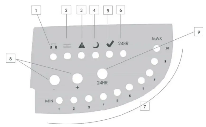
LED INDICATORS
- Cell life low. Illuminates when the cell reaches the end of its expected life. In this case, the cell electrodes have to be replaced.
- No flow. Water flow is not detected, or water flow is too low. If operation schedule is not active, no action should be done, otherwise refer to the Troubleshooting guide (Chapter 12).
- Alarm. The unit is not working properly. Refer to the Troubleshooting guide (Chapter 12).
- Stand-by. The unit is in-between operation cycles.
- Normal operation. Electrolytic cell is generating chlorine under normal conditions.
- Superchlorination. Superchlorination mode is active. Electrolytic cell will be generating chlorine during 24 hours.
- Work schedule. These 10 LEDs, from 1 to 10, correspond to a working hour, each LED represents 6 minutes. If all 10 LEDs illuminate, the unit will be generating chlorine without stop. If 5 LEDs illuminate, the unit will be generating chlorine during 30 minutes of each working hour.

CONTROL BUTTONS - Work schedule control: Press “+” and “-” to adjust working time. The LEDs below will illuminate os explained above.
- Superchlorination: Press the button to activate Superchlorinotion mode. The cell will be generoting chlorine during 24 hours. To exit superchlorination mode, press the button again.
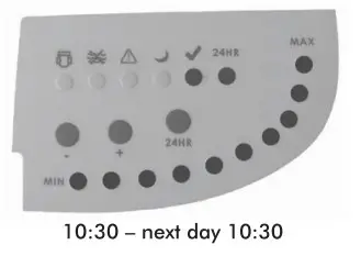
EXAMPLE
If you start SSCminim at 9:00 and set the work schedule at 5, then the unit will be working from 9:00 to 9:30 (Normal operation LED is ON) and in stond-by mode from 9:30 to 10:00 (Stand-by LED is ON).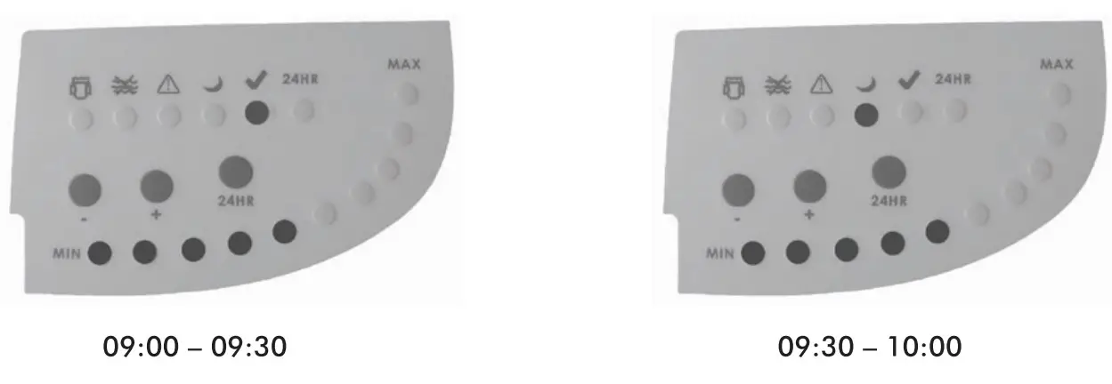
A new cycle will start at 10:00 until 10:30, and so on.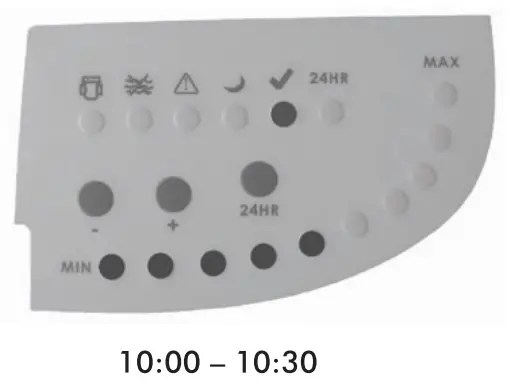
If you activate Superchlorinotion mode of 10:30 (Superchlorination LED is ON), then the unit will be working until 10:30 of the next day and will exit Superchlorination mode afterwards. Once finished Superchlorination, the schedule will be restored and a new cycle will start.
MAINTENANCE
Due to the Reverse Polarity system that avoids scale in the plates of the cell, the first action to consider for ensuring a long cell lifetime is to keep the chemical parameters always in the recommended range, especially the amount of salt, the pH and the water hardness.
- Keep the salinity of the water always higher than 3000 ppm in order to ovoid premature deterioration of the cell plates. The following formula determines the amount of salt to be added in the pool due to low salinity:
Q = (4-S) x V
Where Q = quantity of salt (kg) to be added.
4 = correct salt concentration (constant).
S = Measured salt content in the pool
V = Volume of the pool in m3. - Keep the pH between 7.2 and 7.6. Check and clean the cell plates if the system has been working for o prolonged period with a pH value over 7.6.
ELECTROLYTIC CELL CLEANING PROCEDURE
If scale has formed on the titanium plates, the first cleaning procedure is os follows:
- Switch off the power supply of SSCmini° control unit and remove electrodes from the cell.
- Once removed, look inside and inspect for stole formation on the plates and for any debris which has passed through the filter and caught on the plates.
- Try to remove the scale using o plastic or wooden tool (do NOT use metal os this will scratch the coating off the plates).
If the scale still remains on the plates, proceed the cell cleaning with acid solution:
- Dilute hydrochloric acid with water: one part of acid in 10 pads of water. ATTENTION! }woys odd acid into the water, NEVER odd water into the acid. This prevents splashing of the acid when the water hits it. Wear rubber gloves and appropriate eye protection.
- Submerge the cell plates in the solution for no more than 10 minutes. Plates plastic housing can be submerged in the solution, but avoid any contact with the cell connections and wires.
- Rinse the cell with a high pressure hose. If any deposits are still visible, repeat socking and rinsing.
- If scaling persists, replace the cell by a new one.
WINTERIZING
During o long non-working period, such os winter, the following procedure must be carried out:
- Switch off 5.5Cmini control unit and disconnect it from power supply.
- Drain all water from the electrolytic cell, as well os filtration pump, filter and piping.
- Clean the cell plates with fresh water and dry them with o soft cloth. Check if scaling has been formed. If so, proceed with cleaning of the cell plates (see chapter 10).
TROUBLESHOOTING
SSCminis salt chlorinator informs the user about operation status and alerts about any problems that may hove occurred. Apart from tell life love and No flow° indicators, a combination of “Alarm” and one of “Work schedule” LEDs (from 1 to ID) will illuminate to inform about a fault type.
| Work schedule LED | ||
| INDICATOR | POSSIBLE PROBLEM | SOLIJDON |
| CM LIFE LOW | Cell life ender | Cell electrodes ititonium plotesl ham to be replaced os soon os possible. |
| NO FLOW | Inadequate Water Flow (only if siond.bry mode is not active) | Ensure that water flow rale of your Filtration system a enough to fill the cell completely. |
| Check if hfhotion pump is working properly. that there ore no obstructions in the pool plumbing or pump pnekhec | ||
| Filter tockwashing might be necessary. | ||
| LED 1 / 2 CELL FAULT | Scale formation | Clean the electrolytic cell Chapter 10 |
| Incorrect Water salinity | Test water salinity and adjust it (see Chapter 6.3). Ensure that !rotor flow rote of your fihrotion system is enough to fill the cell completely. | |
| Inadequate tote Water Flow | Check if Rho:Mon pump is working properly. that Mere ore no obstructions in the pool plumbing or pump prefilter. | |
| LED 3 | Incorrect power supply | Disconnect the unit from power supply for two minutes and then connect it again |
| Ensure that SSCmini* is receiving 220V-240VAC 50/60H input. | ||
| LED 4 | Water temperature out of working range | Test water temperature. B it is lower than 10°C, use your heating system to reach proper temperature; if it Is higher than 45t. turn off your hooting sssterri or use other rrothods to cool the water. |
| LED 5/6 | Low salinity and / or High temperature | Test water salinity and odium a (see Chapter 6.3) Test water temperature. If it is higher than 45°C, turn off your healing system or use other methods to cool the rooter. |
| LED7/9 | Unknown | Disconnect the unit from power supply for two minutes ond then connect it again. If this error continues, contact technical sencce. |
| LED 8 CELL FAULT | Scale formation | Clean the electrolytic cell (see Chapter 10) |
| Inadequate Water Flow | Ensure that water flow rote of your filtration system is enough to fill the cell completely | |
| Check 4 filtration pump is working properly, awl there are no obstructions in the pool plumbing or pump prefilter | ||
| Communication error between cell and control unit | Make sure that the cell cop is properly plugged in and that the wire to the Control Box is not cut or damaged. | |
| LED 10 | Communication error between cell ond control unit | Make sure that the Cell cop is properly plugged in and that the Control Box is not cut or damaged. |
PART LIST
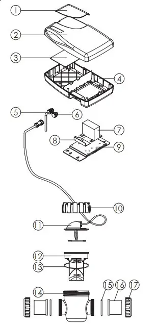
| Item | Part No. | Part Name | QTY |
| 1 | 530095108 | Transparent Lid | 1 |
| 2 | 530085586 | Chlorinator Top Cover | 1 |
| 106855108 | Switch keys | 1 | |
| 3 | 106255294 | Control electronic board( 230/ 240V) | 1 |
| 4 | 530145108 | lower lid | 1 |
5 | 106231416 | Lock for Cable | 1 |
| 105021259 | Cable and Euro Plug | 1 | |
| 105005227 | Cable | 1 | |
| 105011249 | Cable and Australia Plug | 1 | |
| 6 | 106485122 | SP Power Point | 1 |
| 7 | 106161403 | Transformer for SSC25 | 1 |
| 8 | 106441496 | 25 Silicon contrlled combination | 1 |
| 9 | 116095118 | Cooling aluminum | 1 |
| 10 | 530135108 | Electrolytic cell nut | 1 |
| 11 | 89380226 | Five core cable with electronic board | 1 |
| 12 | 89380227 | Electrolyzer body | 1 |
| 13 | 111040010 | O- Ring | 1 |
| 14 | 530045586 | Electrolyzer housing | 1 |
| 15 | 111202472 | O- Ring | 2 |
| 16 | 430300943 | 1. 5″ Union | 2 |
| 430300989 | 2. 0″ Union | 2 | |
| 17 | 430170991 | 2. 0″ Nut | 2 |
INSTALLATION TEMPLATE
Ratio 1:1