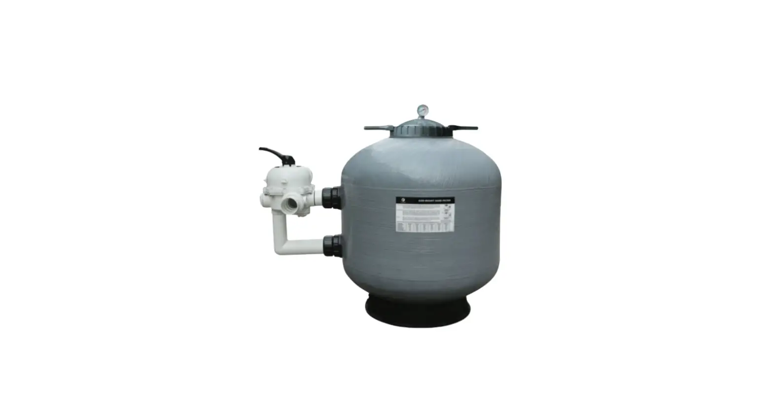
FLOTIDE S450R Side Mount Sand Filter

Product Information
The product in question is a sand filter with a multipurpose control valve. The sand filter comes in four different models: S450R, S500R, S650R, and S700R. The filter tank size and sand diameter vary between models. The control valve has different positions for different functions like normal filtration, backwash, rinse, waste, recirculating, and closing. The valve also has a pipe tap boss for an optional influent pressure gauge. The replacement parts of the filter and multipoint valve are also listed in the manual.
Product Usage Instructions
- Before installation or changing the valve position, turn off the pump.
- Install the filter coping with O’ring in place and screw the pressure gauge carefully into the tapped hole. Do not over-tighten. Ensure that the air relief valve is a tight fit to the filter coping and turns easily.
- Connect the pump to the control valve opening marked PUMP and make a return to the pool pipe connection to the control valve opening marked RETURN. Complete other necessary plumbing connections like suction lines to pump, waste, etc.
- Make electrical connections to the pump per pump instructions.
- To prevent water leakage, ensure all pipe connections are tight.
- Once installed, be sure the correct amount of filter media sand is in the tank and all connections are secure.
- Depress the control valve handle and rotate to the BACKWASH position to clean the filter by reversing the flow. To prevent damage to the control valve seal, always depress the handle before turning.
- Prime and start the pump according to pump instructions while allowing the filter tank to fill with water.
- During the initial clean-up of the pool water, it may be necessary to backwash frequently due to the heavy initial dirt load in the water.
- The various functions of the valve position can be used according to the requirement. For example, use the RINSE position after backwash to flush dirt from the valve or use the WASTE position for vacuuming to waste or lowering the water level. The valve can also be used for bypassing the filter for circulating water to the pool or shutting off all flow to the filter or pool.
- While servicing the valve, stop the pump and close the gate valve in suction and discharge before proceeding.
FUNCTION
The filter uses special filter sand to remove dirt particles from pool water. The filter sand is loaded into the filter tank and functions as a permanent dirt-removing media. When the control valve is in the FILTER position, the pool water which contains suspended dirt particles is pumped through your piping system and is automatically directed by the patented filter control valve to the top of the filter tank. As the pool water is pumped through the filter, dirt particles are trapped by the sand bed, and filtered out. The cleaned pool water is returned from the bottom of the filter tank, through the control valve and back to the pool through the piping system. This entire sequence is continuous and automatic. It provides for total recirculation of pool water through your filter and piping system.
After a period of time, the accumulated dirt in the filter causes a resistance to flow, and the flow diminishes. This means it is time to clean your filter. With the control valve in the BACKWASH position, the water flow is automatically reversed through the filter so that it is directed to the bottom of the tank, up through the sand, flushing the previously trapped dirt and debris out of the waste line. Once the filter is back-washed of dirt, set the control valve to the RINSE position and run the pump for about 1/2 to I minute, and then set the control valve in the FILTER position, to resume normal filtering.
NOTE: Turn the pump off before changing the valve position.
INSTALLATION
Only basic tools (screwdrivers and wrenches) and pipe sealant for plastic adapters are required to install and maintain the filter.
- The filter should be placed on a level concrete slab, very stable ground, or a similar base. Locate the filter so that the pipe connections and control valve are convenient and easy for operation and maintenance are accessible.
- Filling the sand medium. The filter sand medium is filled through the top opening of the filter.
- Install two O-rings on the side of the filter tank. Close the control valve with pipes, fittings, and Glue to the filter (see illustration on page 4).
- Loosen and remove the filter coupler.
- We recommend filling the tank about 1/3 full with water to steam the sand filling. This protects the side panels underneath the expiry before too hard an impact.
- Pour in the correct amount and quality of filter sand. The sand surface should be smoothed and about to the middle of the filter, the tank are enough.
- Replace filter coping (with O’ring in place).
- Carefully screw the pressure gauge (with O’ring in place) into a tapped hole in the filter coping. Do not over-tighten.
- Ensure the air relief valve (with O’ring in place) is a tight fit to filter coping and turn it easily.
- Connect the pump to the control valve opening marked PUMP.
- Make a return to the pool pipe connection to the control valve opening marked RETURN and complete other necessary plumbing connections, suction lines to pump, waste, etc.
- Make electrical connections to the pump per pump instructions.
- To prevent water leakage, be sure all pipe connections are tight.
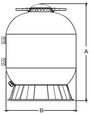
MAIN DIMENSION
DIMENSION TABLE
| Model | High mm A | Diameter mm B | Valve Port Size Inch | Sand Kg |
| S450R | 760 | 455 | 1.5″ | 45 |
| S500R | 825 | 535 | 1.5″ | 85 |
| S650R | 890 | 635 | 1.5″ | 145 |
| S700R | 920 | 723 | 1.5″ | 210 |
INSTALL/START-UP OF FILTER
- Be sure the correct amount of filter media sand is in the tank and that all connections have been made and are secure.
- Depress the control valve handle and rotate to the BACKWASH position. (To prevent damage to the control valve seal, always depress the handle before turning)
- Prime and start the pump according to pump instructions (be sure all suction and return lines are open), allowing the filter tank to fill with water. Once water is flowing out of the waste line, run the pump for at least I minute. The initial back-washing of the filter is recommended to remove any impurities or fine sand particles in the sand media.
- Turn the pump off and set the valve to the RINSE position. Start the pump and operate it until the water in the sight glass is clear, about 1/2 tol a minute. Turn the pump off and set the valve to FILTER position and restart the pump. The filter is now operating in the normal filter mode, filtering dirt particles from the pool water.
- Adjust pool suction and return valves to achieve the desired flow. Check the system and filter for water leaks and tighten connections, bolts, and nuts, as required.
- Note the initial pressure gauge reading when the filter is clean. (It will vary from pool to pool depending upon the pump and general piping system.) As the filter removes dirt and impurities from the pool water, the accumulation in the filter will cause the pressure to rise and flow to diminish. When the pressure gauge reading is 1.5 bar, higher than the initial “clean” pressure you noted, it is time to backwash the filter (see BACKWASH under filter and control valve functions).
NOTE:
During the initial clean-up of the pool water, it may be necessary to backwash frequently due to the unusually heavy initial dirt load in the water.
REPLACEMENT PARTS
REPLACEMENT PARTS OF FILTER
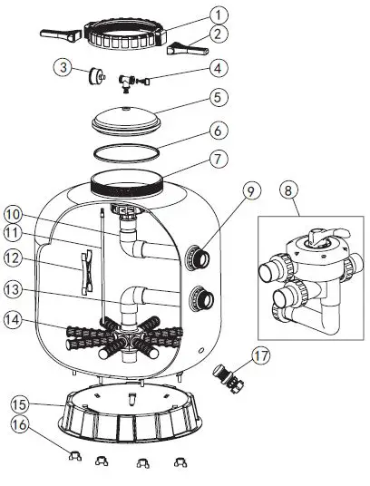
| Key No. | Part No. | Product Description | Qty |
| 1 | 01271012 | Ringlock Nut | 1 |
| 2 | 01021004 | Spanner for RingLock | 2 |
| 3 | 06011029 | Oil Pressure Gauge With O- ring ( 40 psi) | 1 |
| 4 | 89014027 | T- shape Exhuaust Switch | 1 |
| 5 | 01201021 | Cover | 1 |
| 6 | 02010033 | O- Ring for Cover | 1 |
| 7 | 89010648 | S450 RingLocK Filter tank | 1 |
| 89010649 | S500 RingLocK Filter tank | 1 | |
| 89010650 | S650 RingLocK Filter tank | 1 | |
| 89010651 | S700 RingLocK Filter tank | 1 | |
| 8 | 88280805 | 1. 5″ Side Mount Valve | 1 |
| 9 | 89010707 | Connector Plate Side Mount | 1 |
| 10 | 89011309 | The inner tank system for S450R | 1 |
| 89011310 | The inner tank system for S500R | 1 | |
| 89011311 | The inner tank system for S650R | 1 | |
| 89011312 | The inner tank system for S700R | 1 | |
| 11 | 89010708 | S450 Top part of the inner tank system | 1 |
| 89010709 | S500 Top part of the inner tank system | 1 | |
| 89010710 | S650 Top part of the inner tank system | 1 | |
| 89010711 | S700 Top part of the inner tank system | 1 | |
| 12 | 01111046 | Tank System Support | 1 |
| 13 | 89010712 | S450 bottom part of the inner tank system | 1 |
| 89010713 | S500 bottom part of the inner tank system | 1 | |
| 89010714 | S650 bottom part of the inner tank system | 1 | |
| 89010715 | S700 bottom part of the inner tank system | 1 | |
| 14 | 01172007 | S450Laterals ( 115mm) | 8 |
| 01172008 | S500- S700 Laterals ( 126mm) | 8 | |
| 15 | 89010107 | Water Drain Set | 1 |
| 16 | 01111062 | S500- S700 Filter Base with fastener | 1 |
| 17 | 01181052 | Fastener for Filter Base | 4 |
REPLACEMENT PARTS OF THE MULTIPORT VALVE
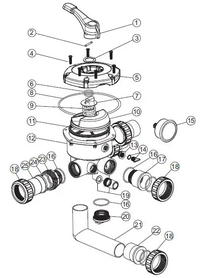
| Key No. | Part No. | Product Description | Qty |
| 1 | 01013002 | Handle ( Small) | 1 |
| 2 | 03018008 | Pin for Handle | 1 |
| 3 | 01181001 | Washer for Handle | 1 |
| 4 | 89281203 | M6×25 Screw with Nut for Camber Lid | 6 |
| 89280107 | M6* 30 Screw with Nut for Standard Lid | 6 | |
| 5 | 01051015 | 1. 5″ Side Mount Valve Camber Lid ( White) | 1 |
| 6 | 02011022 | O- Ring for 1. 5″ Valve Rotor | 2 |
| 7 | 01181002 | Washer for Spring | 1 |
| 8 | 02011002 | O- Ring for 1. 5″ Valve Lid | 1 |
| 9 | 03014001 | Spring for 1. 5″ Simd Mount Valve | 1 |
| 10 | 01021001 | 1. 5″ Valve Rotor | 1 |
| 11 | 02311002 | Spider Gasket | 1 |
| 12 | 01051021 | 1. 5″ Side Mount Valve Bottom Body ( White) | 1 |
| 13 | 01111048 | Connector for Pressure Gauge/ Stopper | 1 |
| 14 | 89021303 | Drain Plug with O- ring | 1 |
| 15 | 06011032 | Oil Pressure Gauge with O- ring ( 40Psi) | 1 |
| 16 | 02020013 | O- Ring | 5 |
| 17 | 01051022 | 1. 5″ Union Tale ( White) | 1 |
| 18 | 01051014 | 1. 5″ Union Nut ( White) | 5 |
| 19 | 89280104 | Sight Glass with O- Ring | 1 |
| 20 | 01051023 | 1. 5″ Side Mount Valve Plug ( White) | 1 |
| 21 | 01051194 | 1. 5″ Elbow Tube ( White) 175mm | 1 |
| 01051193 | 1. 5″ Elbow Tube ( White) 120mm | 1 | |
| 22 | 01171002 | 1. 5″ Union ( Metric) | 1 |
| 23 | 01051013 | 1. 5″ Connector with External Thread( White) | 3 |
| 24 | 02011003 | O- Ring for Union Adaptor | 3 |
| 25 | 01171153 | 1. 5″ Union | 3 |
| 26 | 02011003 | O- Ring | 2 |
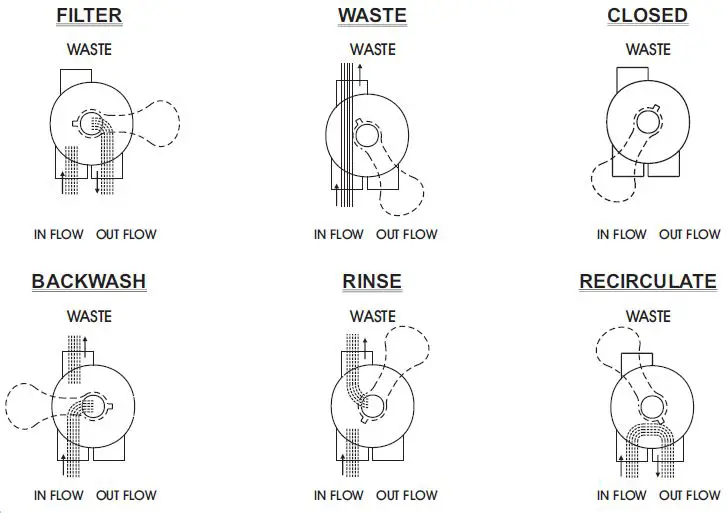
FUNCTIONS OF VALVE POSITIONS
| Valve Position | Function |
| FILTER | Normal Filtration and Vacuuming |
| BACKWASH | Cleaning Filter by reversing the flow |
| RINSE | Used after backwash to flush dirt from valve |
| WASTE | By-passes filter, used for vacuuming to waste or lowering water level |
| RECIRCULATE | By-passes filter for circulating water to pool |
| CLOSED | Shuts off all flow to filter or pool |
GENERAL
- Pipe tap boss provided for optional influent pressure gauge.
- SERVICING VALVE( Stop pump.close gate valve in suction&discharge before proceeding):
- Set the handle in the filter position.
- Remove cover screws.
- Lift the cover and key assembly out.
TO ASSEMBLE:
- Place valve key so that wedge opening is at TOP port (handle in Filter psn.). The flat edge of the cover screw lug should align with the flat edge of the body screw lug.
- Position cover O’Ring.
- Secure assembly to the body with cover screws. Tighten cover screws evenly and alternately. Do not over-tighten.
WARNING
- THIS FILTER OPERATES UNDER HIGH PRESSURE. WHEN ANY PART OF THE CIRCULATING SYSTEM (c.g.CLAMPPUMP, FILTER, VALVES, ETC.) IS SERVICED, AIR CAN ENTER THE SYSTEM AND BECOME PRESSURIZED. PRESSURIZED AIR CAN CAUSE THE LID OR VALVE TO BE BLOWN OFF WHICH CAN RESULT IN SEVERE INJURY, DEATH, OR PROPERTY DAMAGE
- TURN THE PUMP OFF BEFORE CHANGING THE VALVE POSITION.
- TO PREVENT DAMAGE TO THE PUMP AND FOR PROPER OPERATION OF THE SYSTEM, CLEAN THE PUMP STRAINER AND SKIMMER BASKETS REGULARLY.
- DO NOT UNSCREW THE SCREWS OF THE FLANGE CLAMP WHILE THE PUMP IS RUNNING.
- UNDER LOW-TEMPERATURE SHUT-OFF CONDITIONS, IT IS STRONGLY RECOMMENDED TO TURN TO WINTERISE POSITION AND DISCHARGE ALL THE WATER INSIDE THE FILTER THROUGH THE BOTTOM DRAIN.


