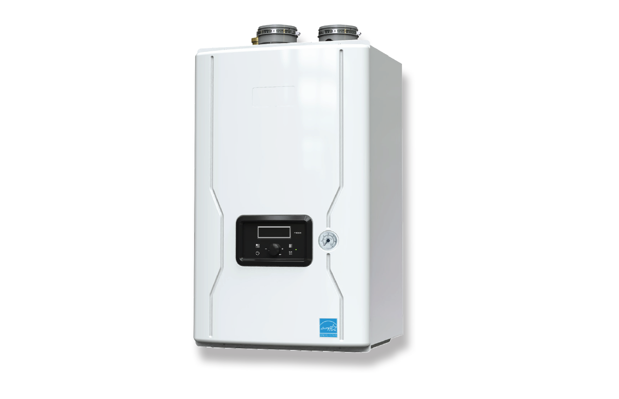
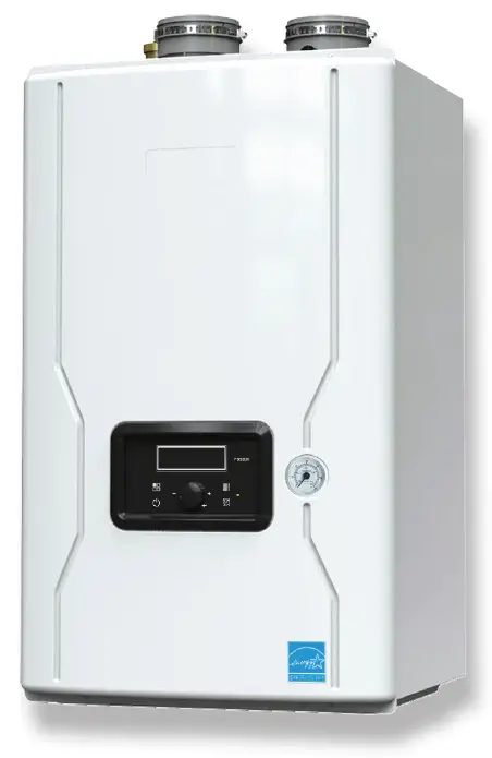
BRADFORD WHITE BMFTHW Brute FT Wall-Hung Boilers 
FOR YOUR SAFETY: This product must be installed and serviced by a professional service technician, qualified in hot water boiler and heater installation and maintenance. Improper installation and/or operation could create carbon monoxide gas in flue gases which could cause serious injury, property damage, or death. Improper installation and/or operation will void the warranty.
WARNING
If the information in this manual is not followed exactly, a fire or explosion may result causing property damage, personal injury or loss of life.
Do not store or use gasoline or other flammable vapors and liquids in the vicinity of this or any other appliance.
WHAT TO DO IF YOU SMELL GAS
- Do not try to light any appliance.
- Do not touch any electrical switch; do not use any phone in your building.
- Immediately call your gas supplier from a nearby phone. Follow the gas supplier’s instructions.
- If you cannot reach your gas supplier, call the fire department.
Installation and service must be performed by a qualified installer, service agency, or gas supplier.
Familiarizing yourself with THE FT SERIES BOILER
The FT Series boiler is a highly efficient, wall mounted, condensing, and fully modulating, residential boiler. This Users Manual will guide you into the basics of operating your
FT Series Boiler.
Please reference the Installation and Operation Manual for complete details. Doc # 1483
| NO | Name of Component |
| 1 | Air Vent (air eliminator) |
| 2 | Air Intake Collar |
| 3 | Air / Gas Mixing Pipe |
| 4 | Gas Inlet Pipe 2 |
| 5 | Gas Valve |
| 6 | Exhaust Duct |
| 7 | Low Water Cut Off |
| 8 | Overheat Temperature Sensor |
| 9 | Flame Detecting Sensor |
| 10 | Main PCB |
| 11 | Control Display |
| 12 | Manual ON/OFF Power Switch |
| 13 | Gas Inlet Pipe 1 |
| 14 | ‘CH’ Internal Pump |
| 15 | Gas Inlet Adapter |
| 16 | ‘CH’ Supply Adapter |
| NO | Name of Component |
| 17 | CH Pressure Gauge |
| 18 | ‘CH’ Return Adapter |
| 19 | Condensate Trap |
| 20 | Condensate Adapter |
| 21 | CH Return Temperature Sensor |
| 22 | Condensate Air Pressure Switch |
| 23 | Terminal Block |
| 24 | Heat Exchanger |
| 25 | Ignition Transformer |
| 26 | Sight Glass |
| 27 | Burner Overheat Switch |
| 28 | Igniter |
| 29 | BLDC Fan (blower) |
| 30 | Exhaust Temperature Sensor |
| 31 | Air Pressure Sensor |
| 32 | Vent Pipe Collar |
OVERVIEW
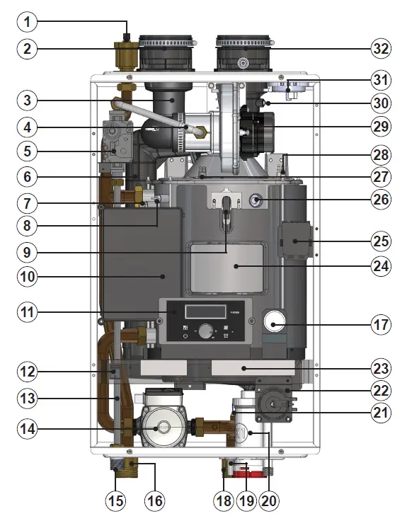
Shown is the FT Series Heating Only 140 MBH. All sizes are very similar in component layout.
Caring For Your FT Series Boiler
Your FT Series boiler will require very little maintenance. However, as with any fine appliance there are certain steps that should be taken to ensure continuing optimum performance.
General Care
- Keep the area around the FT Series boiler clean and free from combustible materials, gasoline and other flammable liquids and vapors.
- The FT Series Boiler must be completely isolated and protected from any source of corrosive chemical fumes such as trichlorethylene, perchlorethylene, chlorine, etc.
- Keep bottom and top openings on the boiler free for proper ventilation of interior components.
- Do not obstruct or block a free flow of air to the boiler to ensure proper ventilation.
- If desired, clean the jacket surfaces with a damp cloth and mild detergent. Do not use flammable cleaning materials.
- If sidewall vented, keep the vent terminal clear of obstructions — do not allow snow to cover the vent terminal. Clean the intake screen often, and then develop an appropriate maintenance schedule.
Annual Inspection of Flue and Vents
Visually inspect the vent pipe once a year. Should any deterioration exist, have the affected parts replaced by a qualified service person.
In the Event of a Power Failure
The FT Series boiler can not be operated during an electrical power outage. If there is an extended power outage with danger from freezing, then the FT Series Boiler (and all other water systems) should be drained completely. When draining the boiler, turn off main electrical disconnect switch. When placing back in service, refer to Section 3 of this Manual for instruction. All draining and filling must only be done by a qualified service person.
Full Service Every Year
In addition to the annual visual inspections, a qualified service agency should conduct a detailed inspection of all flue product carrying areas of the boiler and its venting system.
Shut Down and Restart
To Start the FT Series boiler
If drained, please refer to the Install and Operating Manual to ensure that the complete ‘Setup’ procedure has been followed before starting this boiler. A complete ‘Setup’ must be performed by a qualified service person.
Shutting Down the FT Series boiler
- Turn off the main electrical disconnect switch.
- Close all manual gas valves.
- If freezing is anticipated, drain the FT Series Boiler and be sure to also protect building piping from freezing. All water must be removed from heat exchanger and condensate trap or else damage from freezing may occur. Please refer to the Install and Operating Manual, Doc # 1483 This step to be performed by a qualified service person.
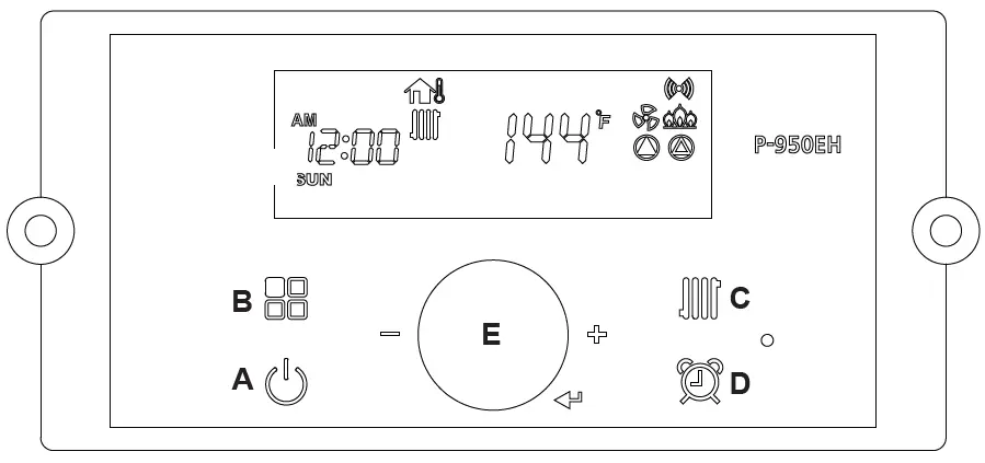
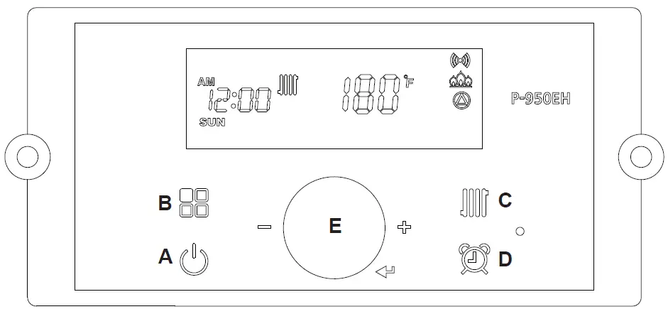
The Control Display and Operation
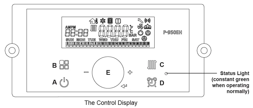
The Control Display has a Control Dial (E), 4 buttons (A, B, C, D), and a Liquid Crystal Display (with 72 back-lit segments). This section of this manual gives instruction on how to navigate into the many functions of the FT and to change temperature set points, set system variables and controller parameters. 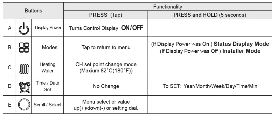
Temperature Specifications
Operating ambient Temperature Range : -10 to 60°C. Operating Relative Humidity up to: 90% at 40°C. Shipping & Storage Temperature Range of : -20 to 80°C.
WARNING Do no use this appliance if any part has been under water. Immediately call a qualifi ed service technician to inspect the appliance and to replace any part of the control system and any gas control that may have been under water. 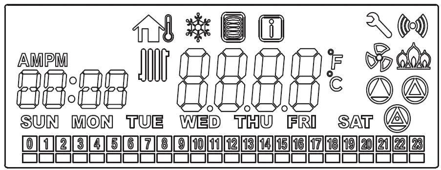
The LCD will illuminate when a user action is detected (a button is pressed) and will turn back off after 20 seconds.
Operating Mode
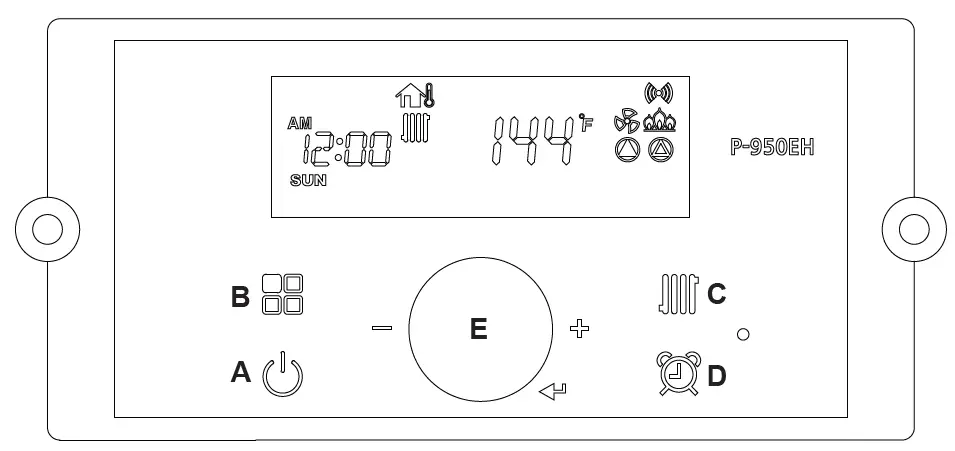
- Operating Mode After the Power is turned on, and/or the Control Display is turned on
 , the Control Display will go through a ‘Start Up’ checklist and briefl y show a sequence of diagnostic codes before entering into the ‘Operating Mode. It will then display the following information.

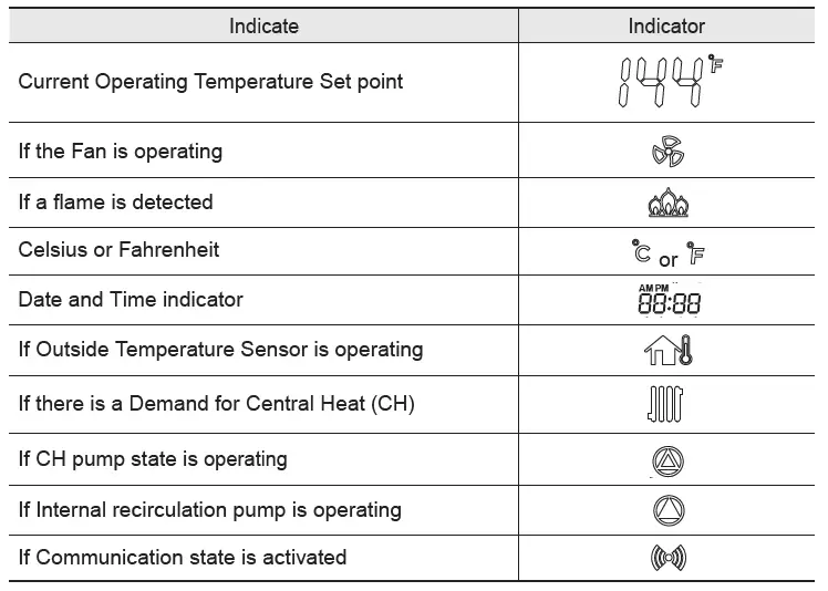
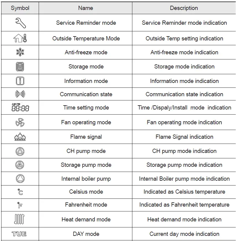
The Control Display can operate through user and service modes that have specific LCD output and dedicated controls:
- Set point change mode
- Lock mode
- Error mode
- Status display mode
- Outside Temperature mode
- Installer mode
* Control Display will not allow changing of button in case of lock mode activated.
Setting the Clock
The P-950EH Control Display does NOT have a daily timer or programmable thermostat. Setting the Clock
- Press and hold the
 ‘Clock button’ for about 5 seconds. Set the ‘Year’ by turning the dial E. And then, press the dial E to Save.
 - Set the ‘MON’ (Month) by turning the dial E to the desired month number. Then press the dial E to Save.
- Set the ‘DATE’ (1-31, Day of the Month) by turning the dial E. Then press the dial E to Save.
- Set the ‘HOUR’ (1-24, Hour of the Day) by turning the dial E. Then press the dial E to Save.
- Set the ‘MIN’ (1-60, Minute of the Hour) by turning the dial E. Then press the dial E to Save.
- Set the ‘Day’ (Sun – Sat) by turning the dial E. Then press the dial E to Save.
To Exit at any time, tap the ![]() button.
button.
5.5 CH Set Point Change Mode
To change CH Set point, press the C ![]() button. The CH Icon and current CH Set point will fl ash.
button. The CH Icon and current CH Set point will fl ash.
Turn the E dial clockwise to increase, and counterclockwise to decrease CH set point, until desired temperature is reached.
Press E dial to save changes and to Exit. 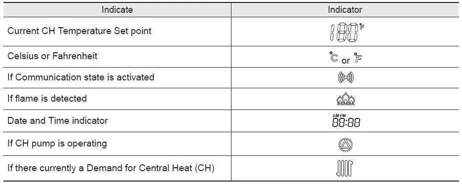
Default CH set point is 180°F (82°C)
CH set point range is 130°F ~180°F (54°C ~ 82.0°C)
Status Display Mode
To view any Status Parameter,
Press and Hold Button B ![]() to get into the Status Display Mode.
to get into the Status Display Mode.
Rotate Dial E until you find the Parameter that you wish to view. Tap Dial E to enter that Parameter as required. Dial E to save and to exit the Status Information Menu. To go back to the Operation Screen Press button B. 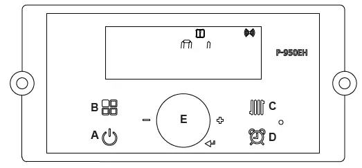
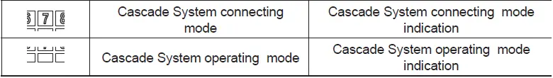
NOTE: For Cascading Installations, please refer to document 1349 ‘Cascading the FT Series Boiler’, available online.
| Digital Display | Status Display Parameter | Description | ||||
| O: ot | Outdoor temperature | Current outdoor sensor temperature | ||||
| A: In | 0-10 V display | Current voltage of (0-10V input) | ||||
| b: tt | CH target temperature in cascade system | Current CH target temperature or Current System target temperature in a cascade system | ||||
| C: It | CH return water temperature | Current CH return water temperature | ||||
| d: Fr | FAN speed ( rpm) | Current FAN speed ( RPM) | ||||
| E: oP | CH supply temperature (Operating temperature) | Current heating temperature | ||||
| F: Eh | Exhaust gas temperature | Current exhaust gas temperature | ||||
| H: dH | Indirect DHW tank temperature * If temperature sensor is not connected then it will display with 0°F (0°C). | Current DHW tank temperature | ||||
| I: oH | Overheat water temperature | Current Overheat water temperature | ||||
|
L: rt | 1: PH |
Burner Operation Time | Time for supply power |
L: rt on display on sub menu | Unit : 1000hour | |
| 2: rh | Time for burner operation | Unit : 1hour | ||||
| 3: rH | Time for burner operation | Unit : 1,000hour | ||||
| 4: It | Cycle for ignition | Cycle : 10 times the displayed unit | ||||
| 5: IH | Cycle for ignition | Cycle : 10,000 times the displayed unit | ||||
|
M: CC | SELF | Percentage of self units running. | Percentage of self units running. | |||
|
ALL |
Capacity for all operating cascade units | Percentage of all cascade units running. This screen shows the overal cascade power output. The range of this value of boilers communicating with theMaster x 100. For example, if 8 boilers are connected and communicating, the maximum cascade power is 800%. Range: 0-100% | ||||
| F1 – F 19 | Capacity for individual boilers | Percentage of each cascade units running. Ex. F1, F2, …. | ||||
| N: St | System Temperature (cascade mode) * If system temperature sensor is not connected then it will display with 0°F (0°C). | Current System Temperature (cascade mode) | ||||
Customer Service and Product Support: 800.900.9276 • Fax 800.559.1583 20 Industrial Way, Rochester, NH, USA 03867


