HIKVISION DS-PM1-O1L-WE Relay Module
Step: 1
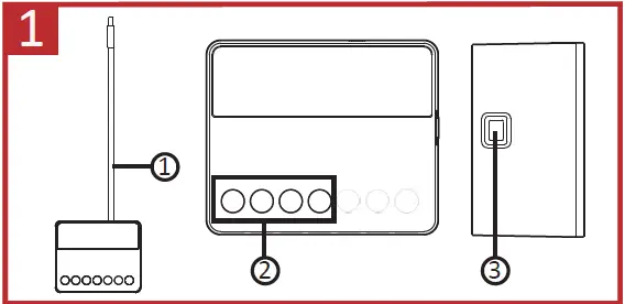
APPEARANCE
- Antenna
- Wiring Terminal
- Learn Button

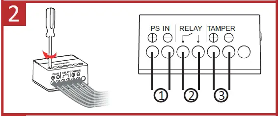
Step: 2
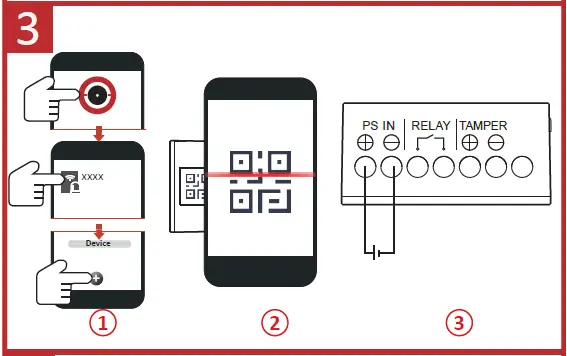
WIRING
- Power Input Wiring
- Relay Output Wiring
- Peripheral Tamper-Proof Wiring

Step: 3
ENROLLMENT
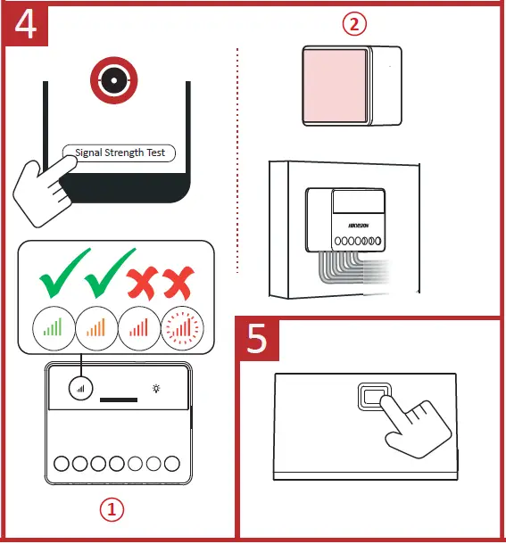
Step: 4
INSTALLATION
Paste the expander in the required place with sponge tape.
Step: 5
FORMATTING
Hold the Learn button for 8 s, and meanwhile power the expander on.
Specification
| Function button | 1, for initialization |
| Scenario settings | By alarm, by operation, by fault,by schedule, by manual |
| Alarm input | 1, for the tamper, NO/NC |
| Relay output Voltage protection | 1, NO/NC (Max.5A at 36 VDC ) Supported, cut off when ≤6.5 V or≥36.5 V |
| RF method | Two-way communication |
| RF frequency | 868 MHz |
| RF distance | 1800 m |
| Power supply | 7 VDC to 24 VDC |
| LEDs status | 3, register/signal (green/red), power (green),relay status (blue) |
| Operation temperature | -10°C to +55°C |
| Operation humidity | 10% to 90% |
| Shell material | Plastic |
| Dimension (W x H xD) | 38 x 25 x 18mm |
| Weight | 28.5 g |
| Installation method | Wall mounting |

More Languages.


