![]() Drain TM 32 Submersible Pumps
Drain TM 32 Submersible Pumps
Instruction Manual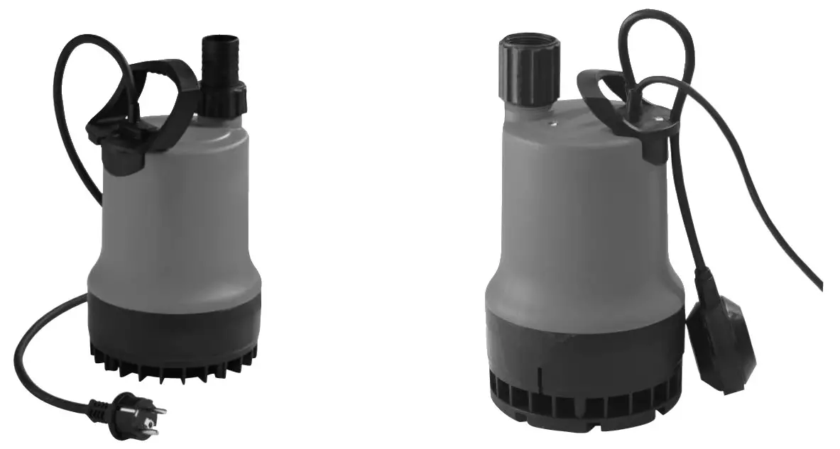
Wilo-Drain TM 32
Wilo-Drain TMW 32
Wilo-Drain TMR 32
Drain TM 32 Submersible Pumps
Safety instructions
About this document
The language of the original operating instructions is English. All other languages of these instructions are translations of the original operating instructions. These installation and operating instructions are an integral part of the product. They must be kept readily available at the place where the product is installed. Strict adherence to these instructions is a precondition for the proper use and correct operation of the product.
This installation and operating instructions correspond to the relevant version of the product and the underlying safety standards valid at the time of going to print. EC declaration of conformity: A copy of the EC declaration of conformity is a component of these operating instructions. If a technical modification is made on the designs named there without our agreement, this declaration loses its validity.
Safety
These operating instructions contain basic information which must be adhered to during installation, operation, and maintenance. For this reason, these operating instructions must, without fail, be read by the service technician and the responsible specialist/ operator before installation and commissioning.
It is not only the general safety instructions listed under the main point “safety” that must be adhered to but also the special safety instructions with danger symbols included under the following main points.
![]() General danger symbol
General danger symbol![]() Danger due to electrical voltage
Danger due to electrical voltage ![]() Note
Note
2.1 Personnel qualifications
The installation, operating, and maintenance personnel must have the appropriate qualifications for this work. Area of responsibility, terms of reference, and monitoring of the personnel are to be ensured by the operator. If the personnel are not in possession of the necessary knowledge, they are to be trained and instructed. This can be accomplished if necessary by the manufacturer of the product at the request of the operator.
2.2 Danger in the event of non-observance of the safety instructions
Non-observance of the safety instructions can result in risk of injury to persons and damage to the environment and the product/unit.
Nonobservance of the safety instructions results in the loss of any claims to damages.
In detail, non-observance can, for example, result in the following risks:
- Danger to persons from electrical, mechanical and bacteriological influences,
- Damage to the environment due to leakage of hazardous materials.
- Property damage
- Failure of important product/unit functions
- Failure of required maintenance and repair procedures
2.3 Safety consciousness on the job
The safety instructions included in this installation and operating instructions, the existing national regulations for accident prevention together with any internal working, operating, and safety regulations of the operator are to be complied with.
2.4 Safety instructions for the operator
This appliance can be used by children aged 8 years and above and persons with reduced physical, sensory or mental capabilities or lack of experience and knowledge if they have been given supervision or instruction concerning the use of the appliance in a safe way and understand the hazards involved. Children shall not play with the appliance. Cleaning and user maintenance shall not be made by children without supervision.
- If hot or cold components on the product/the unit lead to hazards, local measures must be taken to guard them against touching.
- Guards protecting against touching moving components (such as the coupling) must not be removed whilst the product is in operation.
- Leakages (e.g. from the shaft seals) of hazardous fluids (which are explosive, toxic, or hot) must be led away so that no danger to persons or to the environment arises. National statutory provisions are to be complied with.
- Highly flammable materials are always to be kept at a safe distance from the product.
- Danger from electrical current must be eliminated. Local directives or general directives [e.g. IEC, VDE, etc.] and local power supply companies must be adhered to.
2.5 Safety instructions for installation and maintenance work
The operator must ensure that all installation and maintenance work is carried out by authorized and qualified personnel, who are sufficiently informed from their own detailed study of the operating instructions.
Work on the product/unit must only be carried out when at a standstill. It is mandatory that the procedure described in the installation and operating instructions for shutting down the product/unit be complied with. Immediately upon the conclusion of the work, all safety and protective devices must be put back in position and/or recommissioned.
2.6 Unauthorised modification and manufacture of spare parts
Unauthorized modification and manufacture of spare parts will impair the safety of the product/ personnel and will make void the manufacturer’s declarations regarding safety. Modifications to the product are only permissible after consultation with the manufacturer. Original spare parts and accessories authorized by the manufacturer ensure safety. The use of other parts will absolve us of liability for consequential events.
2.7 Improper use
The operating safety of the supplied product is only guaranteed for conventional use in accordance with Section 4 of the operating instructions. The limit values must on no account fall under or exceed those specified in the catalog/datasheet.
General
See the start of the document.
Safety
See the start of the document.
Transport and interim storage
As soon as the product arrives:
- Check the product for damage in transit,
- In the case of transport damage, initiate the necessary procedures with the forwarding agent within the time stipulated.
![]() CAUTION! The danger of property damage!
CAUTION! The danger of property damage!
Incorrect transport and incorrect intermediate storage can lead to product damage.
- The pump may only be suspended/carried by the strap provided for transport purposes. The cable should never be used for lifting!
- The pump must be protected against moisture, frost, and mechanical damage when transported and stored.
Intended use
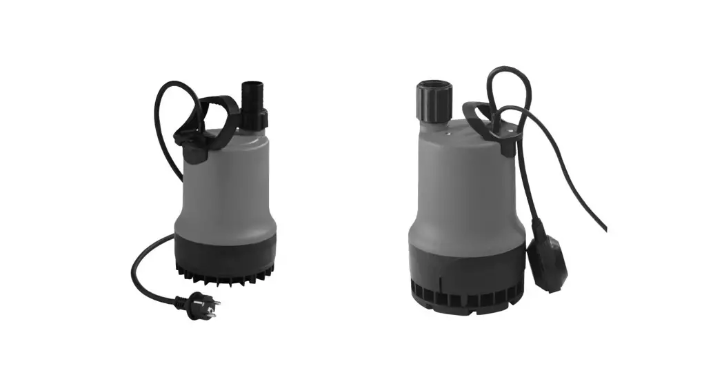
The Drain TM series drainage and submersible wastewater pumps are used.
- for the automatic drainage of pits and shafts, for keeping dry yard areas and basement rooms exposed to flooding,
- and for lowering surface water, if the waste water is not able to flow off into the sewer system through natural fall.
- The pumps are suitable for pumping slightly contaminated water, rainwater, drainage water, and washing water.
TMR pump versions are intended for pumping down to a 2 mm suction level from the floor. This version is recommended for mobile installation and pumping clear water.
The pumps are usually installed underwater (submerged) and can only be permanently or transportable installed vertically. Because of the sheath current cooling, the pumps can also be operated unsubmerged.
Submersible pumps with a mains connection cable of fewer than 10 meters are (according to EN 60335) only permitted for use inside buildings, i.e. not for operating outside. Pumps that are intended for use in or at garden ponds or similar places must have mains connecting cable that is not lighter than rubber-sheathed cables reference H07 RN-F (245 IEC 66) according to EN 60335.
![]() DANGER! Mortal danger due to electric shock! The pump may not be used to drain swimming pools/garden ponds or similar places if anyone is in the water.
DANGER! Mortal danger due to electric shock! The pump may not be used to drain swimming pools/garden ponds or similar places if anyone is in the water.![]() WARNING! Hazardous to health! Owing to the materials used, the pumps are not suitable for potable water! Unpurified foul and wastewater represent a health hazard.
WARNING! Hazardous to health! Owing to the materials used, the pumps are not suitable for potable water! Unpurified foul and wastewater represent a health hazard. ![]() CAUTION! The danger of property damage! Pumping unpermitted substances can lead to product damage. The pumps are not suitable for water with coarse contamination such as sand, fibers, or combustible, caustic fluids or for use in potentially explosive areas. Correct use of the product also includes following these instructions. Any use over and beyond these is interpreted as incorrect use.
CAUTION! The danger of property damage! Pumping unpermitted substances can lead to product damage. The pumps are not suitable for water with coarse contamination such as sand, fibers, or combustible, caustic fluids or for use in potentially explosive areas. Correct use of the product also includes following these instructions. Any use over and beyond these is interpreted as incorrect use.
Product information
5.1 Type key
| Example TM 32/8 -10M – TMW 32/11 HD | |
| TM | Submersible pump |
| W | W = with whirl system (TWISTER-Function) R = low suction version |
| 32 | Nominal diameter of pressure port [mm]: 32 = Rp VA |
| /8 | Max. delivery head [m] when Q = 0m3/h |
| HD | For aggressive water (material 1.4435 (AISI316L) |
| 10M | Length of mains connecting cable [m]: 10 |
| 5.2 Technical data | |
| Main voltage: | see nameplate |
| Main frequency: | see nameplate |
| Protection class: | IP 68 |
| Insulation class: | 155 |
| Speed: | see nameplate |
| Max. current consumption: | see nameplate |
| Power consumption P1: | see nameplate |
| Max. flow rate: | see nameplate |
| Max. delivery head: | see nameplate |
| Operating mode Si: | 200 operating hours a year |
| Operating mode S3 (optimum): | Intermittent duty, 25 % (2.5 min. operations, 7.5 min. intervals). |
| Recommended switching frequency | 20/h |
| Max. switching frequency | 50/h |
| Free ball passage: | 10 mm (model TMR: 2 mm) |
| Nominal diameter of the pressure port: | g 32 mm (Rp 13/4), grooved hose connector 0 35 mm supplied with TM32/7 and TM32/8-10M |
| Admissible fluid temperature: briefly 3 min.: | +3 to 35 °C 90 °C |
| Max. submersion depth : | 4 m connecting cable = lm 10 m (30 m) connecting cable = 3 m |
| Flat suction up to: | 14 mm (model TMR: 2 mm) |
| Maximum fluid density: | 1060 kg/m3 |
5.3 Scope of delivery
Pump with
- 4 m connecting cable with mains plug (Model TM … 10M: 10 m)
- Connected float switch (except TM32/8-10M)
- Whirl self cleaning system (TWISTER function) for TMW
- Pressure port Rp 1¼ (Model TM32/7 and TM32/8-10M: grooved hose connector Ø 35 mm)
- Non-return valve (except TM32/7 and TM32/8-10M)
- Installation and operating instructions
5.4 Accessories
Accessories must be ordered separately (see catalog):
- Switchgear for 1 or 2 pump operation
- Alarm switchgear AlarmControl with mini float switch and plug
- External monitoring devices/tripping unit
- Level control (e.g. flow switch)
- Accessories for transportable wet sump installation (e.g. hose couplings, hoses, etc.).
- Accessories for stationary wet sump installation (e.g. check valves, non-return valves, etc.)
The use of new accessories is recommended.
Description and function
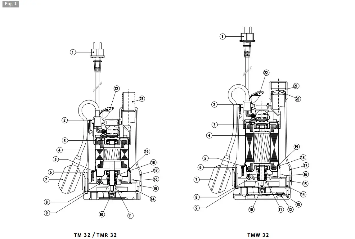
6.1 Description of the product (Fig. 1)
| 1 Cable | 13 Screw |
| 2 Screw | 14 Diffusor |
| 3 O-Ring | 15 Strainer |
| 4 Motor housing | 16 Mechanical seal |
| 5 Screw | 17 O-Ring |
| 6 External housing | 18 Rotary shaft seal |
| 7 Float swich | 19 O-Ring |
| 8 Screw | 20 Non-return valve |
| 9 Screw | 21 Pressure port Rp 1¼ |
| 10 Nut | 22 Handle |
| 11 Impeller | 23 Grooved hose connector |
| 12 Whirl system (TWISTER-Funktion) | |
The pump can be completely submerged in the fluid.
The electric motor is protected against the pump chamber by a rotary shaft seal to seal the motor against the oil chamber and a mechanical seal to seal the oil chamber against the fluid. The mechanical seal chamber is filled with medical white oil so that the mechanical seal is lubricated and cooled during a dry run. A further rotary shaft seal protects the mechanical seal facing the fluid.
The motor is cooled by the surrounding fluid. The pump is installed on the floor of a shaft. For a stationary installation, it is bolted to a fixed pressure pipe, or for a transportable installation, it is connected to a hose connection. The pumps are commissioned by plugging in the protective contact plug. They operate automatically when the float switch switches the pump on from a certain water level “h” (Fig. 2) and switches it off at a minimum water level “h1”.
The motors are equipped with thermal motor protection, which switches off the motor automatically if it overheats and switches it on again when it has cooled down. The condenser is integrated in the single-phase motor.
Version with whirl system (TWISTER-Function)
For wastewater with precipitating and floating particles, the submersible pump has been equipped with a whirl system at the suction strainer. Precipitating particles are continuously whirled up in the suction area of the pump and pumped off with the water. Therefore, mud accumulation in the pump shaft, with problematic consequences such as clogging of the pump and odor formation, is largely prevented. If the removal of the waste water does not allow any interruption, a second pump (automatic standby pump), together with the necessary switchgear (accessory), increases the operating reliability if the 1st pump develops a fault.
Installation and electrical connection
DANGER! Risk of fatal injury!
Incorrect installation and improper electrical.
- The installation and electrical connections should only be done by properly skilled staff and in compliance with the applicable regulations!
- Follow all accident prevention regulations!
7.1 Installation
The pump is designed for stationary or transportable installation.
CAUTION! The danger of property damage!
The danger of damage due to incorrect handling.
Only suspend the pump by the strap with the aid or a chain or rope, never by the electrical or float switch cable or the pipe/hose connection.
The installation site or shaft for the pump must be free of frost.
The shaft must be cleared of coarse material such as rubble before setting up and starting the pump. The quality of the shaft must guarantee the unhindered mobility of the float switch.
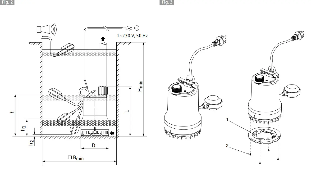
Installation dimension/shaft dimensions (cf. Fig 2).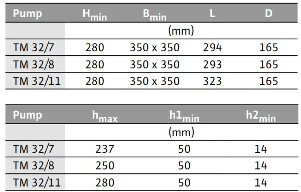
The diameter of the pressure pipe (pipe/hose connection) should not be smaller than the pressure connection of the pipe because of the increased risk of clogging and greater pressure losses. To avoid pressure losses, it is recommended that the pipe connection one number higher is selected.
Stationary wet sump installation
In the case of a stationary wet sump installation of the pump with a permanent pressure pipe, the pump must be positioned and secured so that.
- The pressure pipe connection does not support the weight of the pump.
- The load of the pressure pipe does not act on the connecting socket.
- The pump is installed stress-free.
To protect against any backflow from the public drainage pipe, the pressure pipe must be taken in an arc over the locally established backflow level (usually street level). A non-return valve does not represent a guaranteed backflow seal. - The attached non-return valve should be installed if the pump is installed permanently.
- Seal the pipe connections to the pressure port with Teflon tape.
 NOTE: Permanent leakage in this area can lead to the destruction of the non-return valve and of the screwed connection.
Transportable wet sump installation
In the case of a transportable wet sump installation with a hose connection, the pump must be secured in the shaft to prevent it from falling over and wandering (e.g. secure chain /rope with slight pre-tension).![]() NOTE: When used in a sump without a firm base, the pump must be put on a sufficiently large plate or hung from a rope or a chain in a suitable position.
NOTE: When used in a sump without a firm base, the pump must be put on a sufficiently large plate or hung from a rope or a chain in a suitable position.
7.2 Electrical connection
DANGER! Risk of fatal injury!
If the electrical connection is not made properly, there is a risk of fatal injury from electric shock.
Only allow the electrical connection to be made by an electrician approved by the local electricity supplier and in accordance with the local regulations in force.
- The type of mains connection current and voltage must correspond to the details on the name plate,
- Fuse in the power supply: 10 A, slow,
- Earth the installation according to the regulations,
- The installation of a leakage current protection switch to be provided on-site for a trip current of 30 mA is recommended (caution when installing outside).
- The pump is ready to connect.
To connect the pump to the switchgear, the shock-proof plug is disconnected and the connecting cable is then connected as follows (see Installation and operating instructions for the switchgear): 3-wire connection cable: 3 x 1,0 mm²
| Conductor | Terminal |
| brown | L1 |
| blue | N |
| green/yellow | PE |
Socket and switchgear must be installed in a dry room and protected against flooding.
Commissioning
DANGER! Danger through electric shock!
The pump may not be used to drain swimming pools/garden ponds or similar places if anyone is in the water.
CAUTION! The danger of property damage!
Do not allow the mechanical seal to run dry! Dry running shortens the service life of the motor and the mechanical seal. If the mechanical seal is damaged, small amounts of oil may escape into the pumped fluid.
- When filling the shaft or lowering the pump into the pit, make sure that the float switches can move freely. The switch must switch off the pump before the intake openings of the pump can draw in air.
- After filling the shaft and opening the check valve on the pressure side (if provided), the pump starts up automatically when the switch-on level “h” is reached and switches off as soon as the switch-off level “h1” responds.
- Do not direct the jet of water to be fed into the shaft at the suction strainer of the pump. Entrained air can prevent the operating pump from functioning if the vent slit in the housing is blocked.
- The maximum volume of water entering the shaft must not exceed the performance of the pump. Keep an eye on the shaft when commissioning the pump.
![]() NOTE: The venting of the pump when commissioned for the first time will be improved by submersion in the fluid at an angle or by positioning it at a slight angle.
NOTE: The venting of the pump when commissioned for the first time will be improved by submersion in the fluid at an angle or by positioning it at a slight angle.
Adjusting the switching level of the float switch
The perfect functioning of the level control system is guaranteed if the details according to the table in
7.1 and Fig. 2 are observed.
The switching level (switch-on/off point) can be changed via the free float switch cable by moving the cable within the clip on the pump handle. The level “h2 min” must be respected (see Fig. 2).
On version TMR, to reach the maximum low suction level, the float switch must be manually lifted. A small degree of water evacuation (lateral slit between the suction strainer and housing) when level “h2” is reached is normal and necessary to ensure the operational safety of the pump.
- Do not direct the jet of water to be fed into the shaft at the suction strainer of the pump.
Entrained air can prevent the operating pump from functioning if the vent slit in the housing is blocked. - The maximum quantity of water feeding into the shaft may not exceed the pump‘s capacity.
Monitor the sump during commissioning. - To increase the required capacity (by approx.16% of the delivery head) the whirl system device of the TMW pump can be shut down as follows (fig. 3):
– Pull the mains plug
– Remove the pump from the sump,
– Remove the 4 screws (pos. 2) below the suction basket,
– Remove the whirling device (pos. 1), rotate by 180° and secure again with the 4 screws,
– Lower the pump again and start-up.
Maintenance
Maintenance and repairs may only be carried out by qualified experts!
DANGER! Risk of fatal injury!
There is a mortal danger through shock when working on electrical equipment.
- Before any maintenance and repair work, the pump must be switched off and prevented from being switched on again in an unauthorized manner.
- Damage to the connecting cable may only be repaired by a qualified electrical contractor in principle.
- When checking the function following long downtimes, avoid contact with the fluid.
In order to prevent blockage of the pump resulting from long downtimes, its ability to function should be checked at regular intervals (every 2 months) by the manual raising of the float switch or direct switching-on and brief start-up of the pump. Minor wear of the rotary shaft seal and mechanical seal can lead to fouling of the liquid following an oil leak from the oil chamber.
The pump should therefore be serviced after approx. 2,000 operating hours by a specialist or Wilo After-sales Service, mainly in order to check the seals.
Only specialist companies or Wilo After-sales Service may open the encapsulated motor.
Cleaning the pump
Depending on the use of the pump, fouling can occur within the suction strainer and the impeller. Rinse off the pump under running water after use.
- Switch off the power supply. Disconnect the mains plug!
- Drain the pump
TMW - The whirl device is screwed to the suction strainer (Fig. 3).
• Loosen 4 screws (∅3.5 x 14),
• Remove the whirling device, - The suction strainer is screwed to the pump housing,
• Loosen 4 screws (∅4 x 60),
• Remove the suction strainer, and handle O-ring (∅155 x 2) between the suction strainer/pump housing and the O-ring (∅14 x 2) in the bypass hole (necessary for the whirl function) with care.
TM/TMR - The suction strainer is screwed to the pump housing,
• Loosen 4 screws (∅4 x 60),
• Remove the suction strainer, and handle O-ring (∅155 x 2) between the suction strainer/pump housing with care. - Clean the impeller and pump housing under running water. The impeller must turn freely.
- Replace damaged or worn parts with original spares.
- Re-assembly of the pump in reverse order.
Faults, causes, and remedies
Only have faults remedied by qualified personnel!
Observe safety instructions in 9 Maintenance.
| Fault | Cause | Remedy |
| The pump does not start or stops during operation | Current supply interrupted | Check fuses, cables, and electrical connections |
| The motor protection switch has tripped | Allow the pump to cool down, it will start again automatically | |
| Fluid temperature too high | Allow to cool down | |
| Pump silted up or blocked | Disconnect the pump from the mains and remove it from the shaft. Remove the suction strainer and rinse the suction strainer /impeller under running water | |
| The pump does not switch on/off | The float switch is blocked or cannot move freely | Check the float switch and ensure mobility |
| The pump does not pump | Air in the installation cannot escape | Place the pump at an angle in the water briefly until the air escapes. Vent the installation /drain if necessary Dismantle the suction strainer /whirl device, and rinse the suction strainer /vent slit under running water Check the switch-off level “hi” |
| Water level below the intake port | If possible, submerge the pump deeper (observe the switch-off level) | |
| Pressure pipe/hose diameter too small (losses too high) | Bigger dimensioning of the pressure pipe /hose diameters | |
| Non-return valve sticking in the pressure port | Check function | |
| Hose kinked /check valve closed | Clear kink in hose /open check valve | |
| Flow rate drops during operation | Suction strainer blocked /impeller blocked | Disconnect the pump from the mains and remove it from the shaft. Remove the suction strainer and rinse the suction strainer /impeller under running water |
If the fault cannot be remedied, please contact the trade or your nearest Wilo-After-sales Service or agent
Spare parts
Spares should be ordered through local trade outlets and/or the Wilo-After-sales Service.
To avoid queries and incorrect orders, all the data on the nameplate must be indicated when ordering.
Disposal
Information on the collection of used electrical and electronic products
Proper disposal and appropriate recycling of this product prevent damage to the environment and dangers to your personal health.![]() NOTICE: Disposal in domestic waste is forbidden! In the European Union, this symbol can appear on the product, the packaging or the accompanying documentation. It means that the electrical and electronic products in question must not be disposed of along with the domestic waste. To ensure proper handling, recycling, and disposal of the used products in question, please note the following points:
NOTICE: Disposal in domestic waste is forbidden! In the European Union, this symbol can appear on the product, the packaging or the accompanying documentation. It means that the electrical and electronic products in question must not be disposed of along with the domestic waste. To ensure proper handling, recycling, and disposal of the used products in question, please note the following points:
- Only hand over these products at designated, certified collecting points.
- Observe the locally applicable regulations! Please consult your local municipality, the nearest waste disposal site, or the dealer who sold the product to you for information on proper disposal. For further information on recycling, go to www.wilo-recycling.com. Subject to change without prior notice!
EU/EC DECLARATION OF CONFORMITY
We, the manufacturer, declare under our sole responsibility that the pump types of the series,
TM32/…
TMR32/…
TMW32/…
The serial number is marked on the product site plate
In their delivered state comply with the following relevant directives:
Low voltage 2014/35/EU
Restriction of the use of certain hazardous substances 2011/65/EU and with the relevant national legislation, comply also with the following relevant harmonized European standards:
 Digital
unterschrieben von
Holger
Herchenhein
Datum: 2017.12.15
07:58:02 +01’00’
Wilo – International (Subsidiaries)
| Argentina WILO SALMSON Argentina S.A. C1295ABI Ciudad Autónoma de Buenos Aires T+ 54 11 4361 5929 [email protected] Austria WILO Pumpen Österreich GmbH 1230 Wien T +43 507 507-0 [email protected] Azerbaijan WILO Caspian LLC 1065 Baku T +994 12 5962372 [email protected] Belarus WILO Bel OOO 220035 Minsk T +375 17 2503393 [email protected] Belgium WILO SA/NV 1083 Ganshoren T +3224823333 [email protected] Bulgaria WILO Bulgaria Ltd. 1125 Sofia T +359 2 9701970 [email protected] Canada WILO Canada Inc. Calgary, Alberta T2A 5L4 T +1 403 2769456 [email protected] China WILO China Ltd. 101300 Beijing T +861058041888 [email protected] Croatia WILO Hrvatska d.o.o. 10090 Zagreb T +38 51 3430914 [email protected] Czech Republic WILO Praha s.r.o. 25101 Cestlice T +420 234 098711 [email protected] | Denmark WILO Danmark A/S 2690 Karlslunde T +45 70 253312 [email protected] Estonia WILO Eesti OÜ 12618 Tallinn T +372 6509780 [email protected] Finland WILO Finland OY 02330 Espoo T +358 207401540 [email protected] France WILO S.A.S. 78390 Bois d’Arcy T +33 1 30050930 [email protected] Great Britain WILO (U.K.) Ltd. DE14 2WJ BurtonUpon-Trent T +44 1283 523000 [email protected] Greece WILO Hellas AG 14569 Anixi (Attika) T +302 10 6248300 [email protected] Hungary WILO Magyarország Kft 2045 Törökbálint (Budapest) T +36 23 889500 [email protected] India WILO India Mather and Platt Pumps Ltd. Pune 411019 T +91 20 27442100 service@pun. matherplatt.co.in Indonesia WILO Pumps Indonesia Jakarta Selatan 12140 T +62 21 7247676 [email protected] | Ireland WILO Engineering Ltd. Limerick T +353 61 227566 [email protected] Italy WILO Italia s.r.l. 20068 Peschiera Borromeo (Milano) T +39 25538351 [email protected] Kazakhstan WILO Central Asia 050002 Almaty T +7 727 2785961 [email protected] Korea WILO Pumps Ltd. 621-807 Gimhae Gyeongnam T +82 55 3405890 [email protected] Latvia WILO Baltic SIA 1019 Riga T +371 67 145229 [email protected] Lebanon WILO SALMSON Lebanon 12022030 El Metn T +961 4 722280 [email protected] Lithuania WILO Lietuva UAB 03202 Vilnius T +370 5 2136495 [email protected] The Netherlands WILO Nederland b.v. 1551 NA Westzaan T +31 88 9456 000 [email protected] Norway WILO Norge AS 0975 Oslo T +47 22 804570 [email protected] Poland WILO Polska Sp. z.o.o. 05-090 Raszyn T +48 22 7026161 [email protected] | Portugal Bombas Wilo-Salmson Portugal Lda. 4050-040 Porto T +351 22 2080350 [email protected] Romania WILO Romania s.r.l. 077040 Com. Chiajna Jud. Ilfov T +40 21 3170164 [email protected] Russia WILO Rus ooo 123592 Moscow T +7 495 7810690 [email protected] Saudi Arabia WILO ME – Riyadh Riyadh 11465 T +966 1 4624430 [email protected] Serbia and Montenegro WILO Beograd d.o.o. 11000 Beograd T +381112851278 [email protected] Slovakia WILO Slovakia s.r.o. 82008 Bratislava 28 T +421 2 45520122 [email protected] Slovenia WILO Adriatic d.o.o. 1000 Ljubljana T +38615838130 [email protected] South Africa Salmson South Africa 1610 Edenvale T +27 11 6082780 errol.cornelius@ salmson.co.za Spain WILO Ibérica S.A. 28806 Alcalá de Henares (Madrid) T +34 91 8797100 [email protected] | Sweden WILO Sverige AB 35246 Växjö T +46 470 727600 [email protected] Switzerland EMB Pumpen AG 4310 Rheinfelden T +41 61 83680-20 [email protected] Taiwan WILO-EMU Taiwan Co. Ltd. 110 Taipeh T +886 227 391655 nelson.wu@ wiloemutaiwan.com.tw Turkey WILO Pompa Sistemleri San. ve Tic. A.S¸. 34530 Istanbul T +90 216 6610211 [email protected] Ukraina WILO Ukraina t.o.w. 01033 Kiew T +38 044 2011870 [email protected] United Arab Emirates WILO Middle East FZE Jebel Ali – Dubai T +971 4 8864771 [email protected] USA WILO-EMUUSA LLC Thomasville, Georgia 31792 T +1 229 5840097 [email protected] WILO USA LLC Melrose Park, Illinois 60160 T +1708 3389456 [email protected] Vietnam WILO Vietnam Co Ltd. Ho Chi Minh City, Vietnam T +84 8 38109975 [email protected] |
Wilo – International (Representation offices)
| Algeria Bad Ezzouar, Dar El Beida T +213 21 247979 Armenia 375001 Yerevan T +374 10 544336 Bosnia and Herzegovina 71000 Sarajevo T +387 33 714510 | Georgia 0179 Tbilisi T +995 32 306375 Macedonia 1000 Skopje T +389 2 3122058 Mexico 07300 Mexico T +52 55 55863209 | Moldova 2012 Chisinau T +373 2 223501 Rep. Mongolia Ulaanbaatar T +976 11 314843 Tajikistan 734025 Dushanbe T +992 37 2232908 | Turkmenistan 744000 Ashgabad T +993 12 345838 Uzbekistan 100015 Tashkent T +998 71 1206774 |
WILO SE
Nortkirchenstraße 100
44263 Dortmund
Germany
T 0231 4102-0
F 0231 4102-7363
[email protected]
www.wilo.de


